Table of Contents
Advertisement
Quick Links
Advertisement
Table of Contents

Related Manuals for LevelOne EAP-300


Summary of Contents for LevelOne EAP-300
-
Page 1: User Manual
LevelOne EAP-300 Enterprise Access Point User Manual V1.00... -
Page 2: Table Of Contents
1.2 Document Conventions ..........................3 1.3 Package Content ............................3 2. System Overview and Getting Started ................... 4 2.1 Introduction of LevelOne EAP-300 ......................4 2.2 Deployment Topology ..........................5 2.3 Hardware Description ..........................6 2.4 Hardware Installation ..........................8 2.5 Console Interface ............................ -
Page 3: Before You Start
This manual is intended for system integrators, field engineers, and network administrators to set up LevelOne’s EAP-300 802.11n/a/b/g Enterprise Access Point in their network environments. It contains step-by-step procedures and visual examples to guide MIS staff or individuals with basic network system knowledge to complete the installation. -
Page 4: System Overview And Getting Started
LevelOne WES feature makes it easy to bridge wireless links of multiple EAP-300s for forming wider wireless network coverage. EAP-300 also features multiple ESSIDs with VLAN tags; one EAP-300 can emulate up to eight Virtual APs, great for enterprise applications, such as separating the traffics of different departments using different ESSIDs. -
Page 5: Deployment Topology
This above deployment scenario illustrates a deployment example using three access points, AP-1, AP-2, and AP-3. • Three EAP-300 systems construct a network comprising of wired and wireless segments • AP-2 plays the role of a wireless bridge. • All devices share the same DHCP server 192.168.1.1... -
Page 6: Hardware Description
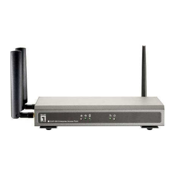
Section 2.03 2.3 Hardware Description This section depicts the hardware information including all panel description. Connector Panel EAP-300 Connector Panel Console Attach the serial cable here. Press once to restart the system; Press and hold for more than 5 Restart/Reset Button seconds to reset to factory default. - Page 7 LED Panel EAP-300 LED Panel LED ON indicates power on; OFF indicates power off. LED OFF indicates RF is not ready; ON indicates RF is ready; CLINKING indicates transmitting/receiving data. LED ON indicates Ethernet cable connected; OFF indicates no connection.
-
Page 8: Hardware Installation
2. Connect the EAP-300 to your network device. Connect one end of the Ethernet cable to LAN port of EAP-300 and the other end of the cable to a switch, a router, or a hub. EAP-300 is then connected to your existing wired LAN network. -
Page 9: Console Interface
Section 2.05 2.5 Console Interface Via this port to enter the console interface for the administrator to check the IP address of EAP-300 and reset the device to default if the admin password is forgotten. 1. In order to connect to the console port of EAP-300, a console, modem cable and a terminal simulation program, such as the Hyper Terminal are needed. - Page 10 When resetting the device to default from the console interface, key in “reset2def” for login and password. Confirm “yes” and EAP-300 will begin the reset process. When the login prompt reappears, the device has completed the reset to default process and the LAN IP is...
-
Page 11: Access Web Management Interface
Section 2.06 2.5 Access Web Management Interface LevelOne EAP-300 supports web-based configuration. Upon the completion of hardware installation, EAP-300 can be configured through a PC by using its web browser such as Mozilla Firefox 2.0 (and higher) or Internet Explorer version 6.0 (and higher). - Page 12 The Web Management Interface - System Overview Page...
- Page 13 • To logout, simply click on the Logout button at the upper right hand corner of the interface to return to the Administrator Login Page. Click OK to logout. Logout Logout Prompt For security reasons, it is strongly recommended to change the administrator’s password upon the completion of all configuration settings.
- Page 14 It is strongly recommended to make a backup copy of configuration settings. • After the EAP-300’s network configuration is completed, please remember to change the IP Address of your PC Connection Properties back to its original settings in order to ensure that...
-
Page 15: Connect Your Ap To Your Network
LAN port and provide wireless access to your network. After having prepared the EAP-300’s hardware for configuration, set the TCP/IP settings of administrator’s computer to have a static IP Address of 192.168.1.10 and Subnet Mask of 255.255.255.0. - Page 16 From here, click on the System icon to arrive at the following page. On this Page you can make entries to the Name, Description, and Location fields as well as set the device’s time. System Information Page There are two methods of setting up the time: Manual (indicated by the option Set Date & Time) and NTP.
- Page 17 Step 2: Configuring the AP’s Network Settings While still on this Page, click on the Network Interface tab to begin configuration of the network settings. Network Settings Page If the deployment decides the AP will be getting dynamic IP Addresses from the connected network, set Mode to DHCP;...
- Page 18 Step 3: Configure the AP’s Wireless General Settings Click on the Wireless icon followed by the General tab. On this page we only need to choose the Band and Channel that we wish to use. Wireless General Settings Page On this page, select the Band with which the AP is to broadcast its signal. The rest of the fields are optional and can be configured at another time.
- Page 19 Step 4: Configuring Wireless Coverage (VAP-1) To setup the AP’s wireless access, refer to the following VAP-1 configuration (other VAP configuration can refer to the same setup steps as done for VAP-1). Click on the Overview tab to proceed. Virtual AP Overview Page On this page click the hyperlink in the row and column that corresponds with VAP-1’s State.
- Page 20 The desired VAP profile can be selected from the drop-down menu of Profile Name and VAP-1 configuration will serve as an example for all other VAPs. Before proceeding further, please make sure that the VAP field is Enable; afterwards, enter an ESSID to represent the WLAN associated with AP’s VAP-1.
-
Page 21: Adding Virtual Access Points
Article IV. Adding Virtual Access Points EAP-300 possesses the feature of multi-ESSID; namely, it can behave as multiple virtual access points, providing different levels of services from the same physical AP device. Please click on the Wireless icon to review the VAP Overview page. - Page 22 Please select the desired VAP profile from the drop-down menu of Profile Name. Choose Enable for the VAP field. Pick a descriptive Profile Name and an appropriate ESSID for clients to associate to. A VLAN ID can be provided to indicate the traffics through this particular VAP. It may allow further management/control (e.g.
-
Page 23: Secure Your Ap
Article V. Secure Your AP Different VAP may require different level of security. These instructions will guide the user through setting up different types of security for a particular VAP. Simply repeat the following steps for other VAP with security requirement. Step 1: Ensure that your VAP is Enabled VAP Overview Page On the VAP Overview page, check the table to confirm the VAP State. - Page 24 Step 2: Configure Security Settings for your VAP Now, we will proceed to secure your AP. The following instructions allow you to secure it using a wireless standard encryption. If you wish to only restrict MAC addresses, skip to the Step3. If you want to also include MAC restrictions, include the following step.
- Page 25 • None: Authentication is not required and data is not encrypted during transmission when this option is selected. This is the default setting as shown in the following figure. Security Settings: None • WEP: WEP (Wired Equivalent Privacy) is a data encryption mechanism with key length selected from 64-bit, 128-bit, or 152-bit.
- Page 26 • 802.1X: When 802.1X Authentication is selected, RADIUS authentication and enhanced dynamic WEP are provided. Security Settings: 802.1X Authentication Dynamic WEP Settings: Dynamic WEP: For 802.1X security type, Dynamic WEP is always enabled to automatically generate WEP keys for encryption. WEP Key Length: Select from 64-bit or 128-bit key length.
- Page 27 • WPA-PSK: Provide shared key authenticaiton in WPA data encryption. Security Settings: WPA-PSK Cipher Suite: Select an encryption method from TKIP (WPA), AES (WPA), TKIP (WAP2), AES (WAP2), or Mixed. Pre-shared Key Type: Select a pre-shared key type: PSK (Hex) or Passphrase. Pre-shared Key: Enter the key value for the pre-shared key;...
- Page 28 • WPA-RADIUS: Authenticate users by RADIUS and provide WPA data encryption. Security Settings: WPA-RADIUS WPA Settings: Cipher Suite: Select an encryption method from TKIP (WPA), AES (WPA), TKIP (WAP2), AES (WAP2), or Mixed. Group Key Update Period: The time interval for the Group Key to be renewed; the time unit is in seconds.
- Page 29 Step 3: Configuring MAC ACL (Access Control List) Click on the hyperlink corresponding with your VAP in the MAC ACL column. You will be brought to the Access Control Settings page. Access Control Settings Page Please choose among Disable, Allow, Deny, and RADIUS ACL from the drop-down menu of Access Control Type.
- Page 30 MAC ACL Deny List: This means that all client devices are granted with access to the system except those listed in the Deny List (“denied MAC addresses”). The administrator can allow any denied MAC address to connect to the system temporarily by checking Enable. MAC ACL Deny List...
- Page 31 RADIUS ACL: Authenticate incoming MAC addresses by an external RADIUS server. When RADIUS ACL is selected, all incoming MAC addresses will be authenticated by an external RADIUS server. Please note that each VAP’s MAC ACL and its security type (shown on the Security Settings page) share the same RADIUS configuration.
-
Page 32: Create A Wds Bridge Between Two Aps
WDS link creation will assist to extend network coverage where running wires is not an option, effectively transferring the traffics to the other end of WLAN/LAN through the EAP-300. Since this is a peer to peer connection, both EAP-300s will be configured by the same way. - Page 33 Step 2: Prevent Loops if Connecting Many AP’s When many APs are linked in this manner, undesired loops may form to lower overall WLAN performance. To prevent such occurrence, please make sure Layer 2 STP is enabled. To turn on this feature, please click on the System and then Network Interface tab. Network Settings Page Please select Enable in the field labeled Layer2 STP.
-
Page 34: Interface Configuration
Web Management Interface Configuration This chapter will guide you through the EAP-300’s detailed settings. The following table shows all the User Interface (UI) functions of LevelOne’s EAP-300 Enterprise Access Point. The Web Management Interface (WMI) is the page where the status is displayed, control is issued and parameters are configured. In the Web Management Interface, there are two main interface areas: Main Menu and Working Area. - Page 35 Reboot OPTION FUNCTION Overview Associated Clients Status Repeater Event Log On each and every configuration page, you may Click Save to save the changes, but you must reboot the system upon the completion of all configurations settings for the changes to take effect. When clicking Save, the following Note: message will appear: “Some modification has been saved and will take effect after Reboot.”...
-
Page 36: System
Section 7.01 7.1 System Found after clicking on the System button, this section allows for general configurations of the devices (e.g. Time Setup, Network Configurations, and System Logs). This section includes the following functions: General, Network Interface, Management, and GRE Tunnel. (a) 7.1.1 General System Information Page System Information... - Page 37 Enable NTP: By selecting Enabled NTP, EAP-300 can synchronize its system time with the NTP server automatically. While this method is chosen, at least one NTP server's IP address or domain name must be provided. NTP Time Configuration Fields Generally networks would have a common NTP server (internal or external). If there is, use it, otherwise locate a nearby NTP server on the web.
-
Page 38: Network Interface
• Layer 2 STP: If the EAP-300 is set up to bridge other network components, this option can be enabled to prevent undesired loops because broadcasting storm may occur in a multi-switch environment where broadcast packets are forwarded in an endless loop between switches. Moreover, a broadcast storm may consume most of available system resources in addition to available bandwidth. -
Page 39: Management
7.1.3 Management The EAP-300’s provided services (e.g. VLAN Management, SNMP, and System log) can be configured here. Management Services Page • VLAN for Management: When enabling this function, management traffic from the system will be tagged with a VLAN ID. In other words, administrator who wants to access the WMI must send management traffic with the same VLAN ID such as connecting to the VAP with the same VLAN ID. - Page 40 • SNMP Configuration: By enabling SNMP function, the administrator can obtain the system information remotely. SNMP Configuration Fields Enable/ Disable: Enable or Disable this function. Community String: The community string is required when accessing the Management Information Base (MIB) of the system. o Read: Enter the community string to access the MIB with Read privilege.
-
Page 41: Gre Tunnel
Key string will be passed to the corresponding EAP-300 and its WMI page will automatically open to confirm the changes. Click Restart link and EAP-300 will restart to activate the tunnel. A new window will automatically open and display the tunnel settings from the AP side which is passed from the Controller. -
Page 42: Wireless
An overall status is collected on this page, including ESSID, State, Security Type, MAC ACL, and Advanced Settings where EAP-300 has 8 VAPs; each having its own settings. In this table, please click on the hyperlink to further configure each individual VAP. - Page 43 • State: The hyperlink showing Enable or Disable connects to the VAP Configuration page. VAP – State Page • Security Type: The hyperlink showing the security type connects to the Security Settings Page. VAP – Security Type Page...
- Page 44 • MAC ACL: The hyperlink showing Allow or Disable connects to the Access Control Settings Page. Access Control Settings Page • Advanced Settings: The advanced settings hyperlink connects to the Advanced Wireless Settings Page. Advanced Wireless Settings Page...
-
Page 45: General
(b)7.2.2 General AP’s general wireless settings can be configured here: AP General Settings Page • Band: Select an appropriate wireless band: 802.11b, 802.11g, 802.11b+802.11g, 802.11g+802.11n or select Disable if the wireless function is not required. Pure 11n: Enable 802.11n network only. •... - Page 46 from the access point. **Due to RF regulation in different nations, available values in the above table will differ. Table 2 RF Configurations (under normal circumstances in certain countries) Band Channel Rate Power Disable 36, 40, 44, 48, 52, 56, 60, 6M, 9M, 12M, 18M, 24M, 64, 100, 104, 108, 112, 802.11a...
-
Page 47: Vap Configuration
• ESSID: ESSID (Extended Service Set ID) is the unique SSID used by a client device to associate with the specified VAP. ESSID determines the service level assigned to a client. • VLAN ID: EAP-300 supports tagged VLANs (virtual LANs). To enable VLAN function, each VAP must have a unique VLAN ID; valid values range from 1 to 4094. -
Page 48: Security
(d) 7.2.4 Security EAP-300 supports various wireless authentication and data encryption methods in each VAP profile. With this, the administrator can provide different service levels to clients. The security type includes None, WEP, 802.1X, WPA-PSK, and WPA-RADIUS. • None: Authentication is not required and data is not encrypted during transmission when this option is selected. - Page 49 802.11 Authentication: Select from Open System, Shared Key, or Auto. WEP Key Length: Select from 64-bit, 128-bit, 152-bit key length. WEP Key Format: Select from ASCII or Hex format for the WEP key. WEP Key Index: Select a key index from 1~4. The WEP key index is a number that specifies which WEP key us used for the encryption of wireless frames during data transmission.
- Page 50 Specify a port number or use the default, 1813. Accounting Interim Update Interval: The system will update accounting information to the RADIUS server every interval period. • WPA-PSK: WPA-PSK (Wi-Fi Protected Access Pre-shared Key) is a pre-shared key authentication method, a special mode of WPA. Security Settings: WPA-PSK Cipher Suite: Select an encryption method from TKIP (WPA), AES (WPA), TKIP (WAP2), AES (WAP2), or Mixed.
-
Page 51: Repeater
Accounting Interim Update Interval: The system will update accounting information to the RADIUS server every interval period. (e) 7.2.5 Repeater To extend wireless network coverage, EAP-300 supports 3 options of Repeater type, None, WDS or Universal Repeater; selecting None will turn off this function. Universal Repeater... - Page 52 Security Type (None, WEP, or WPA-PSK) can be configured for this Repeater connection. Please note the security type configured here shall follow upper-bound AP’s for intended connection. Repeater Settings: Universal Repeater The SSID of Upper-Bound AP: Specify the SSID of the upper-bound AP that the system is used to extend that AP’s wireless service coverage.
- Page 53 If WDS is selected, EAP-300 can support up to 4 WDS links to its peer APs. Security Type (None, WEP, or WPA/PSK) can be configured to decide which encryption to be used for WDS connections respectively. Please fill in remote peer’s MAC address and click SAVE to proceed; if setting revision is necessary, CLEAR button is used to clear the contents in the above WDS connection list.
-
Page 54: Advanced
The RTS mechanism will be activated if the data size exceeds the value provided. A lower RTS Threshold setting can be useful in areas where many client devices are associating with EAP-300 or in areas where the clients are far apart and can detect only EAP-300 but not each other. - Page 55 This option works with WMM-capable clients only. <To receive the benefits of WMM QoS> The application must support WMM. ▬ WMM shall be enabled on EAP-300. ▬ WMM shall be enabled in the wireless adapter on client’s computer. ▬ •...
-
Page 56: Access Control
(g) 7.2.6 Access Control On this page, the network administrator can restrict the total number of clients connected to the EAP-300, as well as specify particular MAC addresses that can or cannot access the device. Access Control Settings Page •... - Page 57 • Access Control Type The administrator can restrict the wireless access of client devices based on their MAC addresses. Disable Access Control: When Disable is selected, there is no restriction for client devices to access the system. MAC ACL Allow List: When selecting MAC ACL Allow List, only the client devices (identified by their MAC addresses) listed in the Allow List (“allowed MAC addresses”)are granted with access to the system.
- Page 58 MAC ACL Deny List: When selecting MAC ACL Deny List, all client devices are granted with access to the system except those listed in the Deny List (“denied MAC addresses”). The administrator can allow any denied MAC address to connect to the system temporarily by checking Disable.
- Page 59 RADIUS ACL: Authenticate incoming MAC addresses by an external RADIUS. When RADIUS ACL is selected, all incoming MAC addresses will be authenticated by an external RADIUS. Please note that each VAP’s MAC ACL and its security type (shown on the Security Settings page) share the same RADIUS configuration.
-
Page 60: Site Survey
(h) 7.2.7 Site Survey Sit Survey is a useful tool to provide information about the surrounding wireless environment; available APs are shown with their respective SSID, MAC Address, Channel, Rate setting, Signal reading, and Security type. The administrator can click Setup or Connect to configure the wireless connection according to the mentioned readings when Repeater Type is Universal Repeater. - Page 61 WPA-PSK: Click Setup to configure the WPA-PSK setting for associating with the target AP. The following configuration box will then appear at the bottom of the screen. Information provided here must be consistent with the security settings of the target AP.
-
Page 62: Firewall
Section 7.03 7.3 Firewall The system provides an added security feature, Layer2 Firewall, in addition to typical AP security. Layer2 Firewall offers a firewall function that is tailored specifically for Layer2 traffics, providing another choice of shield against possible security threats coming from/going to WLAN (AP interfaces); hence, besides firewall policies configured on gateways, this extra security feature will assist to mitigate possible security breach. - Page 63 >>To delete a specific rule, Del in Setting column of firewall list will lead to the following page for removal confirmation. After SAVE button is clicked and system reboot, the rule will be removed. >>To edit a specific rule, Ed in Setting column of firewall list will lead to the following page for detail configuration. From this page, the rule can be edited from scratch or an existing rule for revision.
- Page 64 VLAN ID (when EtherType is 802.1 Q): The VLAN ID is provided to associate with certain VLAN-tagging traffics. Priority (when EtherType is 802.1 Q): It denotes the priority level with associated VLAN traffics. Encapsulated Type (when EtherType is 802.1 Q): It can be used to indicate the type of encapsulated traffics.
- Page 65 Please make sure all desired rules (state of rule) are checked and saved in overview page; the rule will be enforced upon system reboot.
-
Page 66: Service
(when EtherType is IPv4). EAP-300 provides a list of rules to block or pass traffics of layer-3 or above protocols. These services are available to choose from drop-down list of layer2 firewall rule edit page with Ether Type to be IPv4. The first 28 entries are default services and the administrator can add/delete any extra desired services. -
Page 67: Advanced
(c) 7.3.3 Advanced Advanced firewall settings are used to supplement the firewall rules, providing extra security enhancement against DHCP and ARP traffics traversing the available interfaces of system. Trust Interface: Each VAP interface can be checked individually to mark as trusted interfaces; security enforcements on DHCP/ARP like DHCP snooping and ARP inspection will be carried out on non-trusted interfaces. -
Page 68: Utilities
Section 7.04 7.3 Utilities The administrator can maintain the system on this page: Change Password, Backup & Restore, System Upgrade, and Reboot. (a) 7.3.1 Change Password To protect the Web Management Interface from unauthorized access, it is highly recommended to change the administrator’s password to a secure password. -
Page 69: Backup & Restore
(b)7.3.2 Backup & Restore This function is used to backup and restore the EAP-300 settings. The EAP-300 can also be restored to factory defaults using this function. It can be used to duplicate settings to other access points (backup settings of this system and then restore on another AP). -
Page 70: System Upgrade
(c) 7.3.3 System Upgrade The EAP-300 provides a web firmware upload / upgrade feature. The administrator can download the latest firmware from the website and save it on the administrator’s PC. To upgrade the system firmware, click Browse to choose the new firmware file you downloaded onto your PC and then click Upload to execute the process. -
Page 71: Reboot
(d) 7.3.4 Reboot This function allows the administrator to restart the EAP-300 safely. The process shall take about three minutes. Click Reboot to restart the system. Please wait for the blinking timer to complete its countdown before accessing the system’s Web Management Interface again. The System Overview page will appear after reboot successfully. -
Page 72: Status
Section 7.05 7.4 Status This page is used to view the current condition and state of the system and includes the following functions: Overview, Associated Clients, Repeater and Event Log. (a) 7.4.1 Overview The System Overview page provides an overview of the system status for the administrator. System Overview Page... - Page 73 Table 3 Status Page's Organizational Layout Item Description System Name The system name of the EAP-300. Firmware Version The present firmware version of the EAP-300 The present firmware build number of the Build Number EAP-300 System Location The location of the EAP-300.
- Page 74 Remote IP The IP Address of AC. The password for the connection.
-
Page 75: Associated Client
(b)7.4.2 Associated Client The administrator can remotely oversee the status of all associated clients on this page. When a low SNR is found here, the administrator can tune the corresponding parameters or investigate the settings of associated clients to improve network communication performance. Associated Client Status Page •... -
Page 76: Repeater
(c) 7.4.3 Repeater The administrator can review detailed information of the repeater function on this page. Information of repeater’s status, mode and encryption is provided. Repeater Status Page Status: The status of the WDS link either Enabled or Disabled. TX Rate: The transmit rate of the WDS link. TX Count: The accumulative number of transmission counts. -
Page 77: Event Log
• Hostname: Indicates which host recorded this event. Note that all events on this page are local events, so the hostname in this field is always the same. However, in remote SYSLOG service, this field will help the administrator identify which event is from this EAP-300. • Process name: Indicate the event generated by the running instance. -
Page 78: Online Help
Section 7.06 7.6 Online Help The Help button is at the upper right corner of the display screen. Click Help for the Online Help window, and then click the hyperlink of the relevant information needed. Online Help Corner... - Page 79 LevelOne EAP-300 Enterprise Access Point User Manual V1.00...
- Page 80 1.2 Document Conventions ..........................3 1.3 Package Content ............................3 2. System Overview and Getting Started ................... 4 2.1 Introduction of LevelOne EAP-300 ......................4 2.2 Deployment Topology ..........................5 2.3 Hardware Description ..........................6 2.4 Hardware Installation ..........................8 2.5 Console Interface ............................
- Page 81 This manual is intended for system integrators, field engineers, and network administrators to set up LevelOne’s EAP-300 802.11n/a/b/g Enterprise Access Point in their network environments. It contains step-by-step procedures and visual examples to guide MIS staff or individuals with basic network system knowledge to complete the installation.
-
Page 82: Getting Started
LevelOne WES feature makes it easy to bridge wireless links of multiple EAP-300s for forming wider wireless network coverage. EAP-300 also features multiple ESSIDs with VLAN tags; one EAP-300 can emulate up to eight Virtual APs, great for enterprise applications, such as separating the traffics of different departments using different ESSIDs. - Page 83 This above deployment scenario illustrates a deployment example using three access points, AP-1, AP-2, and AP-3. • Three EAP-300 systems construct a network comprising of wired and wireless segments • AP-2 plays the role of a wireless bridge. • All devices share the same DHCP server 192.168.1.1...
- Page 84 Section 2.03 2.3 Hardware Description This section depicts the hardware information including all panel description. Connector Panel EAP-300 Connector Panel Console Attach the serial cable here. Press once to restart the system; Press and hold for more than 5 Restart/Reset Button seconds to reset to factory default.
- Page 85 LED Panel EAP-300 LED Panel LED ON indicates power on; OFF indicates power off. LED OFF indicates RF is not ready; ON indicates RF is ready; CLINKING indicates transmitting/receiving data. LED ON indicates Ethernet cable connected; OFF indicates no connection.
- Page 86 2. Connect the EAP-300 to your network device. Connect one end of the Ethernet cable to LAN port of EAP-300 and the other end of the cable to a switch, a router, or a hub. EAP-300 is then connected to your existing wired LAN network.
- Page 87 Section 2.05 2.5 Console Interface Via this port to enter the console interface for the administrator to check the IP address of EAP-300 and reset the device to default if the admin password is forgotten. 1. In order to connect to the console port of EAP-300, a console, modem cable and a terminal simulation program, such as the Hyper Terminal are needed.
- Page 88 When resetting the device to default from the console interface, key in “reset2def” for login and password. Confirm “yes” and EAP-300 will begin the reset process. When the login prompt reappears, the device has completed the reset to default process and the LAN IP is...
- Page 89 Section 2.06 2.5 Access Web Management Interface LevelOne EAP-300 supports web-based configuration. Upon the completion of hardware installation, EAP-300 can be configured through a PC by using its web browser such as Mozilla Firefox 2.0 (and higher) or Internet Explorer version 6.0 (and higher).
- Page 90 The Web Management Interface - System Overview Page...
- Page 91 • To logout, simply click on the Logout button at the upper right hand corner of the interface to return to the Administrator Login Page. Click OK to logout. Logout Logout Prompt For security reasons, it is strongly recommended to change the administrator’s password upon the completion of all configuration settings.
- Page 92 It is strongly recommended to make a backup copy of configuration settings. • After the EAP-300’s network configuration is completed, please remember to change the IP Address of your PC Connection Properties back to its original settings in order to ensure that...
- Page 93 LAN port and provide wireless access to your network. After having prepared the EAP-300’s hardware for configuration, set the TCP/IP settings of administrator’s computer to have a static IP Address of 192.168.1.10 and Subnet Mask of 255.255.255.0.
- Page 94 From here, click on the System icon to arrive at the following page. On this Page you can make entries to the Name, Description, and Location fields as well as set the device’s time. System Information Page There are two methods of setting up the time: Manual (indicated by the option Set Date & Time) and NTP.
- Page 95 Step 2: Configuring the AP’s Network Settings While still on this Page, click on the Network Interface tab to begin configuration of the network settings. Network Settings Page If the deployment decides the AP will be getting dynamic IP Addresses from the connected network, set Mode to DHCP;...
- Page 96 Step 3: Configure the AP’s Wireless General Settings Click on the Wireless icon followed by the General tab. On this page we only need to choose the Band and Channel that we wish to use. Wireless General Settings Page On this page, select the Band with which the AP is to broadcast its signal. The rest of the fields are optional and can be configured at another time.
- Page 97 Step 4: Configuring Wireless Coverage (VAP-1) To setup the AP’s wireless access, refer to the following VAP-1 configuration (other VAP configuration can refer to the same setup steps as done for VAP-1). Click on the Overview tab to proceed. Virtual AP Overview Page On this page click the hyperlink in the row and column that corresponds with VAP-1’s State.
- Page 98 The desired VAP profile can be selected from the drop-down menu of Profile Name and VAP-1 configuration will serve as an example for all other VAPs. Before proceeding further, please make sure that the VAP field is Enable; afterwards, enter an ESSID to represent the WLAN associated with AP’s VAP-1.
- Page 99 Article IV. Adding Virtual Access Points EAP-300 possesses the feature of multi-ESSID; namely, it can behave as multiple virtual access points, providing different levels of services from the same physical AP device. Please click on the Wireless icon to review the VAP Overview page.
- Page 100 Please select the desired VAP profile from the drop-down menu of Profile Name. Choose Enable for the VAP field. Pick a descriptive Profile Name and an appropriate ESSID for clients to associate to. A VLAN ID can be provided to indicate the traffics through this particular VAP. It may allow further management/control (e.g.
- Page 101 Article V. Secure Your AP Different VAP may require different level of security. These instructions will guide the user through setting up different types of security for a particular VAP. Simply repeat the following steps for other VAP with security requirement. Step 1: Ensure that your VAP is Enabled VAP Overview Page On the VAP Overview page, check the table to confirm the VAP State.
- Page 102 Step 2: Configure Security Settings for your VAP Now, we will proceed to secure your AP. The following instructions allow you to secure it using a wireless standard encryption. If you wish to only restrict MAC addresses, skip to the Step3. If you want to also include MAC restrictions, include the following step.
- Page 103 • None: Authentication is not required and data is not encrypted during transmission when this option is selected. This is the default setting as shown in the following figure. Security Settings: None • WEP: WEP (Wired Equivalent Privacy) is a data encryption mechanism with key length selected from 64-bit, 128-bit, or 152-bit.
- Page 104 • 802.1X: When 802.1X Authentication is selected, RADIUS authentication and enhanced dynamic WEP are provided. Security Settings: 802.1X Authentication Dynamic WEP Settings: Dynamic WEP: For 802.1X security type, Dynamic WEP is always enabled to automatically generate WEP keys for encryption. WEP Key Length: Select from 64-bit or 128-bit key length.
- Page 105 • WPA-PSK: Provide shared key authenticaiton in WPA data encryption. Security Settings: WPA-PSK Cipher Suite: Select an encryption method from TKIP (WPA), AES (WPA), TKIP (WAP2), AES (WAP2), or Mixed. Pre-shared Key Type: Select a pre-shared key type: PSK (Hex) or Passphrase. Pre-shared Key: Enter the key value for the pre-shared key;...
- Page 106 • WPA-RADIUS: Authenticate users by RADIUS and provide WPA data encryption. Security Settings: WPA-RADIUS WPA Settings: Cipher Suite: Select an encryption method from TKIP (WPA), AES (WPA), TKIP (WAP2), AES (WAP2), or Mixed. Group Key Update Period: The time interval for the Group Key to be renewed; the time unit is in seconds.
- Page 107 Step 3: Configuring MAC ACL (Access Control List) Click on the hyperlink corresponding with your VAP in the MAC ACL column. You will be brought to the Access Control Settings page. Access Control Settings Page Please choose among Disable, Allow, Deny, and RADIUS ACL from the drop-down menu of Access Control Type.
- Page 108 MAC ACL Deny List: This means that all client devices are granted with access to the system except those listed in the Deny List (“denied MAC addresses”). The administrator can allow any denied MAC address to connect to the system temporarily by checking Enable. MAC ACL Deny List...
- Page 109 RADIUS ACL: Authenticate incoming MAC addresses by an external RADIUS server. When RADIUS ACL is selected, all incoming MAC addresses will be authenticated by an external RADIUS server. Please note that each VAP’s MAC ACL and its security type (shown on the Security Settings page) share the same RADIUS configuration.
- Page 110 WDS link creation will assist to extend network coverage where running wires is not an option, effectively transferring the traffics to the other end of WLAN/LAN through the EAP-300. Since this is a peer to peer connection, both EAP-300s will be configured by the same way.
- Page 111 Step 2: Prevent Loops if Connecting Many AP’s When many APs are linked in this manner, undesired loops may form to lower overall WLAN performance. To prevent such occurrence, please make sure Layer 2 STP is enabled. To turn on this feature, please click on the System and then Network Interface tab. Network Settings Page Please select Enable in the field labeled Layer2 STP.
- Page 112 Web Management Interface Configuration This chapter will guide you through the EAP-300’s detailed settings. The following table shows all the User Interface (UI) functions of LevelOne’s EAP-300 Enterprise Access Point. The Web Management Interface (WMI) is the page where the status is displayed, control is issued and parameters are configured. In the Web Management Interface, there are two main interface areas: Main Menu and Working Area.
- Page 113 Reboot OPTION FUNCTION Overview Associated Clients Status Repeater Event Log On each and every configuration page, you may Click Save to save the changes, but you must reboot the system upon the completion of all configurations settings for the changes to take effect. When clicking Save, the following Note: message will appear: “Some modification has been saved and will take effect after Reboot.”...
- Page 114 Section 7.01 7.1 System Found after clicking on the System button, this section allows for general configurations of the devices (e.g. Time Setup, Network Configurations, and System Logs). This section includes the following functions: General, Network Interface, Management, and GRE Tunnel. (a) 7.1.1 General System Information Page System Information...
- Page 115 Enable NTP: By selecting Enabled NTP, EAP-300 can synchronize its system time with the NTP server automatically. While this method is chosen, at least one NTP server's IP address or domain name must be provided. NTP Time Configuration Fields Generally networks would have a common NTP server (internal or external). If there is, use it, otherwise locate a nearby NTP server on the web.
- Page 116 • Layer 2 STP: If the EAP-300 is set up to bridge other network components, this option can be enabled to prevent undesired loops because broadcasting storm may occur in a multi-switch environment where broadcast packets are forwarded in an endless loop between switches. Moreover, a broadcast storm may consume most of available system resources in addition to available bandwidth.
- Page 117 7.1.3 Management The EAP-300’s provided services (e.g. VLAN Management, SNMP, and System log) can be configured here. Management Services Page • VLAN for Management: When enabling this function, management traffic from the system will be tagged with a VLAN ID. In other words, administrator who wants to access the WMI must send management traffic with the same VLAN ID such as connecting to the VAP with the same VLAN ID.
- Page 118 • SNMP Configuration: By enabling SNMP function, the administrator can obtain the system information remotely. SNMP Configuration Fields Enable/ Disable: Enable or Disable this function. Community String: The community string is required when accessing the Management Information Base (MIB) of the system. o Read: Enter the community string to access the MIB with Read privilege.
- Page 119 Key string will be passed to the corresponding EAP-300 and its WMI page will automatically open to confirm the changes. Click Restart link and EAP-300 will restart to activate the tunnel. A new window will automatically open and display the tunnel settings from the AP side which is passed from the Controller.
- Page 120 An overall status is collected on this page, including ESSID, State, Security Type, MAC ACL, and Advanced Settings where EAP-300 has 8 VAPs; each having its own settings. In this table, please click on the hyperlink to further configure each individual VAP.
- Page 121 • State: The hyperlink showing Enable or Disable connects to the VAP Configuration page. VAP – State Page • Security Type: The hyperlink showing the security type connects to the Security Settings Page. VAP – Security Type Page...
- Page 122 • MAC ACL: The hyperlink showing Allow or Disable connects to the Access Control Settings Page. Access Control Settings Page • Advanced Settings: The advanced settings hyperlink connects to the Advanced Wireless Settings Page. Advanced Wireless Settings Page...
- Page 123 (b)7.2.2 General AP’s general wireless settings can be configured here: AP General Settings Page • Band: Select an appropriate wireless band: 802.11b, 802.11g, 802.11b+802.11g, 802.11g+802.11n or select Disable if the wireless function is not required. Pure 11n: Enable 802.11n network only. •...
- Page 124 from the access point. **Due to RF regulation in different nations, available values in the above table will differ. Table 2 RF Configurations (under normal circumstances in certain countries) Band Channel Rate Power Disable 36, 40, 44, 48, 52, 56, 60, 6M, 9M, 12M, 18M, 24M, 64, 100, 104, 108, 112, 802.11a...
- Page 125 • ESSID: ESSID (Extended Service Set ID) is the unique SSID used by a client device to associate with the specified VAP. ESSID determines the service level assigned to a client. • VLAN ID: EAP-300 supports tagged VLANs (virtual LANs). To enable VLAN function, each VAP must have a unique VLAN ID; valid values range from 1 to 4094.
- Page 126 (d) 7.2.4 Security EAP-300 supports various wireless authentication and data encryption methods in each VAP profile. With this, the administrator can provide different service levels to clients. The security type includes None, WEP, 802.1X, WPA-PSK, and WPA-RADIUS. • None: Authentication is not required and data is not encrypted during transmission when this option is selected.
- Page 127 802.11 Authentication: Select from Open System, Shared Key, or Auto. WEP Key Length: Select from 64-bit, 128-bit, 152-bit key length. WEP Key Format: Select from ASCII or Hex format for the WEP key. WEP Key Index: Select a key index from 1~4. The WEP key index is a number that specifies which WEP key us used for the encryption of wireless frames during data transmission.
- Page 128 Specify a port number or use the default, 1813. Accounting Interim Update Interval: The system will update accounting information to the RADIUS server every interval period. • WPA-PSK: WPA-PSK (Wi-Fi Protected Access Pre-shared Key) is a pre-shared key authentication method, a special mode of WPA. Security Settings: WPA-PSK Cipher Suite: Select an encryption method from TKIP (WPA), AES (WPA), TKIP (WAP2), AES (WAP2), or Mixed.
- Page 129 Accounting Interim Update Interval: The system will update accounting information to the RADIUS server every interval period. (e) 7.2.5 Repeater To extend wireless network coverage, EAP-300 supports 3 options of Repeater type, None, WDS or Universal Repeater; selecting None will turn off this function. Universal Repeater...
- Page 130 Security Type (None, WEP, or WPA-PSK) can be configured for this Repeater connection. Please note the security type configured here shall follow upper-bound AP’s for intended connection. Repeater Settings: Universal Repeater The SSID of Upper-Bound AP: Specify the SSID of the upper-bound AP that the system is used to extend that AP’s wireless service coverage.
- Page 131 If WDS is selected, EAP-300 can support up to 4 WDS links to its peer APs. Security Type (None, WEP, or WPA/PSK) can be configured to decide which encryption to be used for WDS connections respectively. Please fill in remote peer’s MAC address and click SAVE to proceed; if setting revision is necessary, CLEAR button is used to clear the contents in the above WDS connection list.
- Page 132 The RTS mechanism will be activated if the data size exceeds the value provided. A lower RTS Threshold setting can be useful in areas where many client devices are associating with EAP-300 or in areas where the clients are far apart and can detect only EAP-300 but not each other.
- Page 133 This option works with WMM-capable clients only. <To receive the benefits of WMM QoS> The application must support WMM. ▬ WMM shall be enabled on EAP-300. ▬ WMM shall be enabled in the wireless adapter on client’s computer. ▬ •...
- Page 134 (g) 7.2.6 Access Control On this page, the network administrator can restrict the total number of clients connected to the EAP-300, as well as specify particular MAC addresses that can or cannot access the device. Access Control Settings Page •...
- Page 135 • Access Control Type The administrator can restrict the wireless access of client devices based on their MAC addresses. Disable Access Control: When Disable is selected, there is no restriction for client devices to access the system. MAC ACL Allow List: When selecting MAC ACL Allow List, only the client devices (identified by their MAC addresses) listed in the Allow List (“allowed MAC addresses”)are granted with access to the system.
- Page 136 MAC ACL Deny List: When selecting MAC ACL Deny List, all client devices are granted with access to the system except those listed in the Deny List (“denied MAC addresses”). The administrator can allow any denied MAC address to connect to the system temporarily by checking Disable.
- Page 137 RADIUS ACL: Authenticate incoming MAC addresses by an external RADIUS. When RADIUS ACL is selected, all incoming MAC addresses will be authenticated by an external RADIUS. Please note that each VAP’s MAC ACL and its security type (shown on the Security Settings page) share the same RADIUS configuration.
- Page 138 (h) 7.2.7 Site Survey Sit Survey is a useful tool to provide information about the surrounding wireless environment; available APs are shown with their respective SSID, MAC Address, Channel, Rate setting, Signal reading, and Security type. The administrator can click Setup or Connect to configure the wireless connection according to the mentioned readings when Repeater Type is Universal Repeater.
- Page 139 WPA-PSK: Click Setup to configure the WPA-PSK setting for associating with the target AP. The following configuration box will then appear at the bottom of the screen. Information provided here must be consistent with the security settings of the target AP.
- Page 140 Section 7.03 7.3 Firewall The system provides an added security feature, Layer2 Firewall, in addition to typical AP security. Layer2 Firewall offers a firewall function that is tailored specifically for Layer2 traffics, providing another choice of shield against possible security threats coming from/going to WLAN (AP interfaces); hence, besides firewall policies configured on gateways, this extra security feature will assist to mitigate possible security breach.
- Page 141 >>To delete a specific rule, Del in Setting column of firewall list will lead to the following page for removal confirmation. After SAVE button is clicked and system reboot, the rule will be removed. >>To edit a specific rule, Ed in Setting column of firewall list will lead to the following page for detail configuration. From this page, the rule can be edited from scratch or an existing rule for revision.
- Page 142 VLAN ID (when EtherType is 802.1 Q): The VLAN ID is provided to associate with certain VLAN-tagging traffics. Priority (when EtherType is 802.1 Q): It denotes the priority level with associated VLAN traffics. Encapsulated Type (when EtherType is 802.1 Q): It can be used to indicate the type of encapsulated traffics.
- Page 143 Please make sure all desired rules (state of rule) are checked and saved in overview page; the rule will be enforced upon system reboot.
- Page 144 (when EtherType is IPv4). EAP-300 provides a list of rules to block or pass traffics of layer-3 or above protocols. These services are available to choose from drop-down list of layer2 firewall rule edit page with Ether Type to be IPv4. The first 28 entries are default services and the administrator can add/delete any extra desired services.
- Page 145 (c) 7.3.3 Advanced Advanced firewall settings are used to supplement the firewall rules, providing extra security enhancement against DHCP and ARP traffics traversing the available interfaces of system. Trust Interface: Each VAP interface can be checked individually to mark as trusted interfaces; security enforcements on DHCP/ARP like DHCP snooping and ARP inspection will be carried out on non-trusted interfaces.
- Page 146 Section 7.04 7.3 Utilities The administrator can maintain the system on this page: Change Password, Backup & Restore, System Upgrade, and Reboot. (a) 7.3.1 Change Password To protect the Web Management Interface from unauthorized access, it is highly recommended to change the administrator’s password to a secure password.
- Page 147 (b)7.3.2 Backup & Restore This function is used to backup and restore the EAP-300 settings. The EAP-300 can also be restored to factory defaults using this function. It can be used to duplicate settings to other access points (backup settings of this system and then restore on another AP).
- Page 148 (c) 7.3.3 System Upgrade The EAP-300 provides a web firmware upload / upgrade feature. The administrator can download the latest firmware from the website and save it on the administrator’s PC. To upgrade the system firmware, click Browse to choose the new firmware file you downloaded onto your PC and then click Upload to execute the process.
- Page 149 (d) 7.3.4 Reboot This function allows the administrator to restart the EAP-300 safely. The process shall take about three minutes. Click Reboot to restart the system. Please wait for the blinking timer to complete its countdown before accessing the system’s Web Management Interface again. The System Overview page will appear after reboot successfully.
- Page 150 Section 7.05 7.4 Status This page is used to view the current condition and state of the system and includes the following functions: Overview, Associated Clients, Repeater and Event Log. (a) 7.4.1 Overview The System Overview page provides an overview of the system status for the administrator. System Overview Page...
- Page 151 Table 3 Status Page's Organizational Layout Item Description System Name The system name of the EAP-300. Firmware Version The present firmware version of the EAP-300 The present firmware build number of the Build Number EAP-300 System Location The location of the EAP-300.
- Page 152 Remote IP The IP Address of AC. The password for the connection.
- Page 153 (b)7.4.2 Associated Client The administrator can remotely oversee the status of all associated clients on this page. When a low SNR is found here, the administrator can tune the corresponding parameters or investigate the settings of associated clients to improve network communication performance. Associated Client Status Page •...
- Page 154 (c) 7.4.3 Repeater The administrator can review detailed information of the repeater function on this page. Information of repeater’s status, mode and encryption is provided. Repeater Status Page Status: The status of the WDS link either Enabled or Disabled. TX Rate: The transmit rate of the WDS link. TX Count: The accumulative number of transmission counts.
- Page 155 • Hostname: Indicates which host recorded this event. Note that all events on this page are local events, so the hostname in this field is always the same. However, in remote SYSLOG service, this field will help the administrator identify which event is from this EAP-300. • Process name: Indicate the event generated by the running instance.
- Page 156 Section 7.06 7.6 Online Help The Help button is at the upper right corner of the display screen. Click Help for the Online Help window, and then click the hyperlink of the relevant information needed. Online Help Corner...