Table of Contents
Advertisement
Quick Links
Advertisement
Table of Contents

Related Manuals for Vivotek VS2101


Summary of Contents for Vivotek VS2101
- Page 2 Product name: Video Server (VS2101) Release Date: 2005/06/29 Manual Revision: 2.00 Web site: www.vivotek.com Email: technical@vivotek.com sales@vivotek.com Made in Taiwan. ©Copyright 2000-2005. All rights reserved - 1 -...
- Page 3 Before You Use It is important to carefully examine the contents with the Chapter Package Contents after opening the package. If there is anything missing, contact your reseller. Read the Chapter Physical Description before assembling and operating the device and peripherals.
-
Page 4: Table Of Contents
Table of Contents Before You Use ............2 Package Contents ............. 5 Features and Benefits..........5 Physical Description ..........7 Front Panel ..................7 Rear Panel ..................8 Installation ............11 Ethernet Environment ..............12 Initial Access to the Video Server.............12 Initial Access to the Video Server.............13 Modem Environment ..............14 How to Use ............ - Page 5 Configure System via FTP ...............52 Telnet Commands ................58 Appendix ............... 60 A. Troubleshooting .................60 B. Frequently Asked Questions ............61 C. Upgrade System Firmware ............65 D. URL Commands of Video Server ..........66 E. Settings of Supported PTZ Cameras ..........78 F. Camera Control Cable ..............79 G.
-
Page 6: Package Contents
Package Contents If any of the following items are missing, please contact your reseller. Video Server VS2101 Null modem cable Power adapter Software CD I/O terminal connector Quick installation guide Camera control cable Warranty - 5 -... -
Page 7: Features And Benefits
Features and Benefits Video Server is a high-performance networking video multiplexer. With powerful VLIW DSP core and fully optimized algorithm, it can compress and transmit the high quality real-time video through standard TCP/IP inter-network. In addition to meet the basic needs of video feed, many advanced features are added to help building applications of surveillance or web attraction. - Page 8 security system in your home or office. ☆ Weekly schedule for automatic surveillance The user-defined time period will repeat weekly to check any security settings and accordingly sending notification or drive external devices. It is easy to install in SOHO, retail shop and home as a security system.
-
Page 9: Physical Description
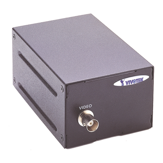
Physical Description Front Panel BNC video input 75Ohms resistance video port for connecting an external camera. To ensure video modulation type being correctly detected, cameras should be attached and powered on before the Video Server is powered on. - 7 -... -
Page 10: Rear Panel
Rear Panel Status LED’s Each time Video Server starts up, it will perform power-on-self-test, abbreviated as POST, to examine every hardware module. As soon as the administrator plugs in the power connector both LED’s under the power LED will flash one by one until the diagnosis is done. -
Page 11: Com Port
COM port This RS232 serial port can connect with a modem or included null modem cable to utilize dial-up network when Ethernet is not available. If Video Server operates with Ethernet interface, administrators may use this port to control PTZ camera attached to VIDEO. General I/O terminal block INPUT (Max. -
Page 12: Restore Button
Restore button There is a button hidden in the box for restoring the system factory default settings. When the system fails to install or operates abnormally, use the included assistant stick in the package and follow the following procedures to reset the system back to its original status. -
Page 13: Installation
Installation To easily fit into various environments, the Video Server automatically detects the attached interfaces and configures itself to the best condition. Therefore users need not care whether the connected cameras are either NTSC or PAL, how to select the network between Ethernet and modem, and whether the Ethernet speed is 10Mbps or 100 Mbps. -
Page 14: Ethernet Environment
Ethernet Environment Hardware installation Before installing multiple Video Server’s at the well-chosen locations, the administrator should memorize the serial numbers on the packages respectively for future use. Cable connection Shut down all the peripheral devices prior to connection. The video BNC, Ethernet cable and power adapter are essential for basic viewing function. -
Page 15: Initial Access To The Video Server
Initial Access to the Video Server The Video Server can be connected either before or immediately after software installation onto the Local Area Network. The Administrator should complete the network settings on the configuration page. For complete protection from illegal usage, the Video Server provides two privileges and always needs user name and password before access. -
Page 16: Modem Environment
Modem Environment Hardware installation Though Video Server is designed to serve real-time images in Ethernet, it also supports the dial-up network. To use a dial-up network, the Ethernet socket should be left disconnected since Ethernet is the first priority among available interfaces. After powering up, Video Server will detect if any external modem is connected to the modem port . - Page 17 Shut down the peripheral devices prior to connection and keep the power adaptor unplugged until other cables are firmly connected. In the environment without Ethernet, administrators can use the included null modem cable to connect to Video Server directly and access point-to-point. After necessary information is entered and saved, turn off Video Server and remove the null modem cable.
-
Page 18: Software Installation
Software installation Via Ethernet Enter the COM configuration Web page and select the driver type as modem. Well configure each field for dialing information. Refer to the COM section in Definition of Configuration for detailed description. Via null modem Install a new modem 1. - Page 19 4. Choose the serial port that the included null modem cable is attached to and click on . The null modem is now ready for use. If no Dial-Up adapter exists in the system, Windows may automatically prompt to install. Press continue.
- Page 20 Setup a new connection 1. After the 33600 bps modem is installed, open the dialup network folder in Windows to build a new connection. 2. Select the device as the newly installed standard 33600 bps modem and click on 3. Just enter arbitrary digits as phone number and click on .
- Page 21 5. Right-click on the newly setup connection icon for entering properties. 6. In the first General page, clear "Use area code and Dialing Properties" option and click on 7. Select 115200 as the speed and click on 8. On the second page, only check "Enable software compression"...
- Page 22 Now the connection is ready to use for null modem. Double click the newly setup connection. A dialing information window will pop up. Enter “root” as user name and the serial number labeled on the bottom side of the box as the password and click on .
- Page 23 First access to Video Server in null modem mode Through direct connection by null modem cable, administrators can connect to “http://200.1.1.1” in the web browser. “200.1.1.1” will be the default IP address of Video Server in dial-in connection; “200.1.1.100” will be the given IP address for the user's PC by Video Server.
- Page 24 First access to Video Server in modem mode If the dial-out is not prohibited and the attached modem is recognized, Video Server will send out the system startup log and connection log by email or FTP according to user’s settings as soon as the system is ready. That can be used to verify if the settings work. Then Video Server will always wait for someone to dial in.
-
Page 25: How To Use
How to Use Open your familiar web browser and connect to Video Server just like a general web site and the video will present on demand. Make sure the web address of the target Video Server is accurate. Authentication After opening the Web browser and typing in the URL of Video Server, a dialogue window will pop out to request a username and password. -
Page 26: Installing Plug-In
Installing Plug-in If it is initial access to Video Server via the Web browser supporting server push, the motioned pictures will display directly. If the Web browser is Internet Explorer in Windows, users will be asked to install a new plug-in that is provided by Video Server. This plug-in has been registered for certificate and is used to display motioned pictures in the Internet Explorer. -
Page 27: Main Page
Main Page Basic functions are displayed in main entrance page of Video Server. The first figure below is graphic mode that has better visual effect and the second one is text mode that will shorten download time. The main page may look different depending on the PTZ driver or the privilege of the user. - Page 28 Text mode Text mode is default if any image button is not available. Video quality selection It allows users to adjust the video quality for speed or smoothness. The performance is also subject to the network bandwidth and the number of users. Five options are available to be chosen from “Medium”...
-
Page 29: System Configuration
in the low bandwidth environment like a dial-up network. To fit into the small image area, timestamp will be skipped in “Half” and “Half×2” modes. System configuration There is a button or text link in the left side of the system configuration that only appears in administrators’... -
Page 30: System Configuration
System Configuration Introduction The system configuration can be easily done remotely on Internet Explorer through the Web interface. There are two wizards in addition to classified categories of system configurations. They can give friendly instructions and facilitate the setup job. Alternately administrators may type directly the URL of system configuration, “http://<IP address of Video Server>/setup/config.html”, to directly enter the configuration page. -
Page 31: Setup Wizard
Setup Wizard The setup wizard will guide administrator to enter necessary information including system name, current date and time, administrator’s password, video configuration and captions, and network settings. Administrators can exit the procedures anytime to reserve the current configuration. Finally the setup wizard will ask for reboot to validate the changes and administrators can decide to reboot later. -
Page 32: Definitions Of Configuration
Definitions of Configuration System parameters Change host name The “host name” is used for the homepage title of main page and displays as the title over the video window on the main page. The maximum string length is 40 characters or 20 characters in double-byte-character-systems like Chinese or Japanese. - Page 33 Security privilege Change root password To change the administrator’s password, type the new password in both text boxes identically. What is typed will be displayed as asterisks for security purposes. The maximum password is 16 characters. After pressing , the web browser will ask administrators for the new password for access.
-
Page 34: Network Settings
Network settings Fix the IP address To eliminate incautious mistakes during installation, Video Server will stay in installation mode whenever it starts unless "Reset network at next boot" is disabled. This option can also be disabled using the Installer program. Once the option is disabled, Video Server will skip installation at the next boot and the Installer program will not find the installed units. - Page 35 rejects upon any failure. Some ISP may reject the mail if the address is invalid. FTP settings To send the log files described in the above paragraph via FTP, the SMTP server should be erased. Administrators must enter correct "Primary FTP Server", "Primary FTP user name"...
- Page 36 default size of video window when users first connect to Video Server. “Default quality” option here will be the default quality when users first connect to Video Server. And the "Modulation" type is auto-detected during initialization, but administrators can still set it manually.
-
Page 37: Com Port Configuration
COM port configuration Choose serial interface There are two types of serial interfaces supported by COM port but only one interface can be used at one time. Administrators must set the correct “Interface mode” between RS232 and RS485 according to the attached device. Choose device driver If the attached device is PTZ driver, administrators should select the appropriate PTZ model. - Page 38 applications, also remember to choose Network option to enter mail server address and recipient's e-mail address. If "Dialout allowed" is not checked, Video Server will not send out any snapshots when events occur and the settings except for "Initial modem command"...
- Page 39 Application constitution Administrators can use combinations of options on the application page to perform many useful security applications. Video Server provides two application modes; one is performed according to the settings on the web page, the other is performed according to the external command script.
- Page 40 event” option to drive some device attached to the digital outputs several seconds after the event happens and/or send snapshots that are taken right at the moment. . If administrators want to receive some snapshots to check the event, please check the “Upload snapshot while input condition match”...
-
Page 41: Homepage Layout
Homepage layout There are two homepage display modes. One is "Image mode" that uses graphics for links; the other is "Text mode" that mostly uses text for links. Administrators may easily give Video Server a different presence of homepage. The "logo graph"... -
Page 42: View Log File
View log file There is some useful information in the system log including current system configuration and activity history with timestamp for tracking. View parameters The whole system parameters will be categorized listed for administrators to check. The content is the same as CONFIG.INI. Factory default It is used to restore the factory default settings. -
Page 43: Advanced Functions
Advanced Functions Capture Up-to-date Still Images Get snapshot via URL Administrator and users can use the specific URL to capture the current still image. http://<IP of Video Server>/cgi-bin/video1.jpg[?<param>=<value>] Additional value Description parameters:param quality Medium Standard Good Detailed Excellent size Half Standard Double Halfx2... - Page 44 Video Embedded in Customers’ Homepage In additional to the URL, some scripts should be added to download a plug-in for motion pictures. The following example simply displays title text and a real-time video window in Internet Explorer or Netscape. The user name and password should be configured in advance.
- Page 45 Download Event-triggered Snapshots There are three video image files for the video channel of three stages: pre-alarm, the moment when triggered and post-alarm. Only the snapshots captured by the last event are preserved. Administrator and users can use FTP or URL to get the saved snapshots. They can also be browsed from the application page in system configuration.
-
Page 46: Uploading Snapshots Periodically
Uploading Snapshots Periodically Upload snapshots to external FTP server In sequential mode, Video Server will send out snapshots according to interval and period settings. If snapshot files are intended for quick updates, it is better to skip date and time suffix. The file name will then be video1.jpg. If the snapshots are used for occasional monitoring, suffix with date and time can help administrators classify them easily. -
Page 47: Customize Graphics In Homepage
Customize Graphics in Homepage While in text mode, there is a small icon named BTN_TEXT.GIF preceding with each link that can be changed by administrators. While in image mode, the default method will use the image stored in Flash memory. The followings are the referenced file name and size limitation of each stored images. -
Page 48: Command Script For Complex Applications
Command Script for Complex Applications Besides the application wizard, Video Server provides a more professional command script for advanced applications. The command script will be executed exclusively with the settings in Application page of system configuration except for the weekly schedule. To build the advanced application, follow the steps below. - Page 49 “Digital input state”: H (high), L (low), / (low to high), \ (high to low) “M”: motion detection event. “Channel Number”: always A “Video input state”: / (signal from loss to presence), \ (signal from presence to loss), X (as long as signal loss) “Delay time”: seconds of delay for the following actions after events happen “Digital output number”: always 1...
-
Page 50: Practical Examples
Practical examples Command line Description MA=1C; When any motion is detected, “Normal Close” of relay output will short with “Common”. 1\=(5)1O; When DI transients from high to low, “Normal Open” of relay output will short with COMMON in 5 seconds. A\=W{192.168.0.1 If there is no video signal, a message “no signal!”... -
Page 51: Url For External Device Control
URL for External Device Control Query status of digital inputs /cgi-bin/getdi.cgi Video Server will return status of four digital inputs in one line. Drive digital outputs /cgi-bin/setdo.cgi?do1=<state> <state>: C, O denoting Normal Close or Normal Open respectively. Move motorized camera in PTZ direction /cgi-bin/control.cgi?<param>=<value>&<param>=<value>……... -
Page 52: Transparent Remote Serial Driver
Transparent Remote Serial Driver Video Server provides a highly customized control support to third-party serial interface devices aside from PTZ cameras. That means in addition to setting up a custom camera with PTZF commands, users may utilize this mode and introduce a customized homepage to transmit arbitrary user-defined commands from user-side to Video Server. -
Page 53: Url Of System Maintenance
URL of System Maintenance Download System Log via FTP Besides viewing the system log from the web page, administrators can download the system log file, SYSTEM.LOG, via FTP. To log into the FTP daemon, enter “root” as the user name and the same administrator’s password used in Web access. Restart System via URL /cgi-bin/reset.cgi Restart Video Server without warning. -
Page 54: Configure System Via Ftp
Video Server Initial Configuration File [SYSTEM] <reset system> or NO <host name> Video Server string of maximum 40 characters <serial number> 0002D1040011 read-only <software version> VS2101-VVTK-0202c read-only <current date> 2004/06/23 read-only <current time> 12:34:56 read-only <time zone> from 12 to -12 <user name>... - Page 55 (10) (11) (12) (13) (14) (15) (16) (17) (18) (19) (20) <user password> (0)0002D1040011 string of maximum 16 characters the followings are as same as the above (10) (11) (12) (13) (14) (15) (16) (17) (18) (19) (20) <more guests enabled> or YES to enable snapshot mode <more guests interval>...
- Page 56 <com speedlink name> string of maximum 8 characters string of maximum 8 characters string of maximum 8 characters string of maximum 8 characters string of maximum 8 characters [NETWORK] <install enabled> reset IP whenever system boots or NO <ppp enabled> obsolete <ethernet address>...
- Page 57 <ftp init path> string of maximum 40 characters <ftp passive> or YES <backup ftp server> IP address or domain name <backup ftp port> or 1024 ~ 65535 <bacup ftp username> string of maximum 16 characters <backup ftp password> string of maximum 16 characters <backup ftp init path>...
- Page 58 <stop bits> <parity bits> <baud rate> <ccd model> <uart mode> RS232 or RS485 <speedlink commands> string of maximum 80 characters string of maximum 80 characters string of maximum 80 characters string of maximum 80 characters string of maximum 80 characters <custom ccd commands>...
- Page 59 <percentage of object size over screen> 1~99 <percentage of sensitivity> 1~99 <tenth seconds to snapshot after event> <snapshots taken after event> <time to start snapshot> 00:00:00 24 hours format <time to stop snapshot> 00:00:00 24 hours format [DEMO] <demo enabled> or YES <PTZ enabled>...
-
Page 60: Telnet Commands
Telnet Commands Video Server has a Telnet daemon for only administrators to access some seldom used functions. Using any general terminal program to connect to Video Server will prompt the user for a password. Username is not requested here since only administrators can access the Telnet daemon. -
Page 61: Erase Snapshots Stored In Flash Memory
Erase snapshots stored in Flash memory Typing "erase image" will clear all snapshots saved in Flash memory. Erase logo and graphic buttons Typing "erase graph" will clear all images used on the homepage. If no new images are uploaded, the system will switch to text mode and use default images instead. Skip installation at next boot Typing "lock"... -
Page 62: Appendix
Appendix A. Troubleshooting Power-On-Self-Test After the power has been turned on, Video Server will perform a self-diagnostic to detect any possible hardware defects. If the power indicator is dim at the beginning, the system fails to proceed further without power. While the POST is proceeding, the status LED indicators will keep blinking interchanged until finished or any fatal error happens. -
Page 63: Frequently Asked Questions
B. Frequently Asked Questions Q Why can’t I see the Video Server in the installer after reboot? A The installer is only used to install the IP address of Video Server. If the IP address is fixed by checking the option in the installer, the Video Server will no longer appear in the installer. - Page 64 Q How can I use a name instead of the IP address to connect Video Server? A To allow users to connect to Video Server through an easily memorized name, the administrators must first configure the name server in his network. Here is an example: the administrator installs the Video Server with a reserved IP address and assigns it with a name in the domain name service, then users can connect to Video Server by typing a name instead of IP address.
- Page 65 2. bandwidth share, 3. number of users, 4. number of video inputs are accessed at one time, 5. the complicated objects in view results in larger image file, 6. the level of your PC or notebook which is responsible of displaying images. In general, the transfer rate in general local network environment can achieve over 200 kilobytes per second and approximately 10 to 20 pictures of normal environment per second.
- Page 66 A If user has defined the snapshot interval, Video Server will capture images periodically as pre-alarm stage. Once the pre-defined condition is match, the pre-alarm images will be kept and the current images will be saved. The subsequent images will be stored as post-alarm stage.
-
Page 67: Upgrade System Firmware
C. Upgrade System Firmware Customers can frequently check the appropriate product folder on our web site to download the latest firmware. Only administrators can upgrade the system firmware of Video Server. Easy way via Upgrade Wizard Run the Upgrade Wizard included in the product CDROM and proceed by the prompts. Refer to the user's guide of Upgrade Wizard for details. -
Page 68: Url Commands Of Video Server
D. URL Commands of Video Server For some customers who already have their own web site or web control application, Video Server can be easily integrated through convenient URL. This section lists the commands in URL format corresponding to the basic functions of Video Server. Some RFC standards related to HTML may be a good reference for implementation of the customized homepage. -
Page 69: System Resource Url
System resource URL There are some images used on the homepage when the homepage layout is in image mode. Administrators may use the following links to show the images saved in Video Server on another page. To change the logo or the background images referenced by the URL, refer to the homepage layout section in configuration. -
Page 70: General Format Of Command Url
General format of command URL Every configuration can be set through URL with POST method by administrators only. <general format> URL[?[name=value][&name=value]……] <method> POST <authorized user> root System configuration URL URL: /cgi-bin/system.cgi NAME VALUE DESCRIPTION host <text string shorter than 15 system name characters>... -
Page 71: Network Configuration Url
characters> slow <not required> Snapshot mode open <not required> enable demo account camctrl <not required> allow demo user to control the PTZ camera demoioallowed <not required> allow demo user to control the I/O access slow <not required> snapshot mode delay <integer>... -
Page 72: Video Configuration Url
mailto2 <text string shorter than 80 mail recipient address characters> returnmail <text string shorter than 80 return address characters> ftp1 <domain name or IP address> primary FTP server ftprp1 <number less than 65535> FTP server port ftpuser1 <text string shorter than 15 user name for primary FTP server characters>... - Page 73 Detailed higher resolution Excellent highest resolution mode Auto let Video Server detect video modulat NTSC set directly to NTSC type set directly to PAL type - 71 -...
-
Page 74: Image Quality Configuration Url
Image quality configuration URL URL: /cgi-bin/image.cgi NAME VALUE DESCRIPTION brightness <-5 ~ 5> adjust brightness of image contrast <-5 ~ 5> adjust contrast of image <-5 ~ 5> adjust hue of image saturation <-5 ~ 5> adjust saturation of image preview <not required>... -
Page 75: Custom Camera Configuration Url
COM configuration URL URL: /cgi-bin/serial1.cgi NAME VALUE DESCRIPTION interface RS232 switch COM to RS232 RS485 switch COM to RS485 detect generic accept generic CGI commands modem use modem none no drivers driver Sony VISCA Canon VCC1 Canon VCC3 Canon VCC4 DynaDome/SmartDOME Pelco D protocol Lilin PIH-7x00... -
Page 76: Camera Custom Command Configuration Url
Camera custom command configuration URL URL: /cgi-bin/cuscom.cgi NAME VALUE DESCRIPTION <text string shorter than 80 tilt up command string of COM characters> down1 <text string shorter than 80 tilt down command string of COM characters> left1 <text string shorter than 80 pan left command string of COM characters>... -
Page 77: Camera Preset Configuration Url
Camera preset configuration URL URL: /cgi-bin/camerasetting.cgi NAME VALUE DESCRIPTION addpos <text string shorter than 40 characters> add preset position delpos <existing position name> delete preset position Modem configuration URL: /cgi-bin/serialmodem.cgi NAME VALUE DESCRIPTION dialout allow Video Server dialing out on event no dial-out allowed method Tone (ATDT) - Page 78 <not required> set Thursday in weekly schedule <not required> set Friday in weekly schedule <not required> set Saturday in weekly schedule sbegin <hh:mm:ss> time to start in weekly schedule send <hh:mm:ss> time to stop in weekly schedule <not required> set inverse mode in weekly schedule enfile <not required>...
-
Page 79: Homepage Layout Configuration Url
Homepage layout configuration URL URL: /cgi-bin/layout.cgi NAME VALUE DESCRIPTION cuslogo blank hide logo use default logo use image from URL logourl <text string shorter than 80 URL of image for logo characters> linkurl <text string shorter than 80 URL to link when clicking on logo characters>... -
Page 80: Settings Of Supported Ptz Cameras
E. Settings of Supported PTZ Cameras Since the COM port settings can be adjusted to other than the default settings, check the correct default settings for the attached camera. Camera model Baud rate Data bits Stop bit Parity bit Sony VISCA 9600 None Canon VC-C1... -
Page 81: Camera Control Cable
F. Camera Control Cable The included cable can be used to control motorized cameras of desktop types from Sony and Canon. The pin assignment is illustrated in the following chart. To control cameras of another brand, check the user’s manual of the motorized camera if the pin assignment of the control cable is appropriate. -
Page 82: Time Zone Table
G. Time Zone Table While setting the time zone in automatic date/time synchronization, find the hour offset in the followings for your region. GMT stands for Greenwich Mean Time, which is the global time that all time zones are measured from. (GMT–12:00) International Date Line West (GMT-11:00) - Page 83 (GMT+01:00) West Central Africa (GMT+02:00) Athens, Istanbul, Minsk (GMT+02:00) Bucharest (GMT+02:00) Cairo (GMT+02:00) Harare, Pretoria (GMT+02:00) Helsinki, Kyiv, Riga, Sofia, Tallinn, Vilnius (GMT+02:00) Jerusalem (GMT+03:00) Baghdad (GMT+03:00) Kuwait, Riyadh (GMT+03:00) Moscow, St. Petersburg, Volgograd (GMT+03:00) Nairobi (GMT+03:30) Tehran (GMT+04:00) Abu Dhabi, Muscat (GMT+04:00) Baku, Tbilisi, Yerevan (GMT+04:30)
- Page 84 (GMT+10:00) Hobart (GMT+10:00) Vladivostok (GMT+11:00) Magadan, Solomon Is., New Caledonia (GMT+12:00) Auckland, Wellington (GMT+12:00) Fiji, Kamchatka, Marshall Is.. (GMT+13:00) Nuku’alofa - 82 -...
-
Page 85: Technical Specifications
H. Technical Specifications System Dimension CPU: Trimedia PNX1300 122.9 mm(L) * 72.3 mm(W) * 50 mm(H) RAM: 16MB SDRAM ROM: 2MB FLASH ROM Weight Networking Adjustable bandwidth limit Net. 340g. Protocol TCP/IP, HTTP, SMTP, FTP, Telnet, NTP, DNS and Power DHCP Consumption: near 4.2W Modem... - Page 86 Vivotek Inc. cannot be held responsible for any technical or typographical errors and reserves the right to make changes to the product and manuals without prior notice. Vivotek Inc. makes no warranty of any kind with regard to the material contained within this document, including, but not limited to, the implied warranties of merchantability and fitness for a particular purpose.