Table of Contents
Advertisement
Quick Links
Download this manual
See also:
Owner's Manual
Advertisement
Table of Contents

Related Manuals for NAD L55


Summary of Contents for NAD L55
- Page 1 DVD/VIDEO CD/CD PLAYER...
- Page 3 PRODUCT SAFETY SERVICING GUIDELINES FOR VIDEO PRODUCTS CAUTION : DO NOT ATTEMPT TO MODIFY THIS PRODUCT IN VOLTAGE MEASURE MUST NOT EXCEED 75 VOLTS R.M.S. ANY WAY. NEVER PERFORM CUSTOMIZED INSTALLATIONS THIS CORRESPONDS TO 0.5 MILLIAMP A.C ANY VALUE WITHOUT MANUFACTURER’S APPROVAL. UNAUTHORIZED EXCEEDING THIS LIMIT CONSTITUTES A POTENTIAL MODIFICATIONS WILL NOT ONLY VOID THE WARRANTY, BUT SHOCK HAZARD AND MUST BE CORRECTED IMMEDIATELY.
-
Page 4: Servicing Precautions
SERVICING PRECAUTIONS CAUTION : Before servicing the DVD player covered by this service Electrostatically Sensitive (ES) Devices data and its supplements and addends, read and follow the SAFETY Some semiconductor (solid state) devices can be damaged easily by PRECAUTIONS. NOTE : if unforeseen circumstances create conflict static electricity. - Page 5 DVD player/Outputs/Supplied Accessories Power supply AC 230V / 50 Hz (EUROPE), AC 110V/60Hz (USA / CANADA) Power consumption 15 W Mass 3.3 kg External dimensions (W X H X D) 285 x 103x 291 mm Signal system PAL (EUR) , NTSC (USA / CANADA) Laser Semiconductor laser, wavelength 650 nm Frequency range (audio)
-
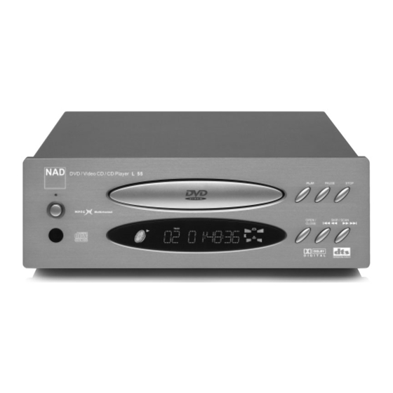
Page 6: Front Panel
Front Panel STOP button POWER indicator (Standby mode: Blue color) PAUSE/STEP button Disc tray PLAY button DISPLAY WINDOW REMOTE SENSOR SKIP/SCAN buttons POWER button OPEN/CLOSE button Display Window OPERATING STATUS indicator Repeat playback mode indicators CD indicator PROGRAM indicator DVD indicator VCD indicator SYSTEM SINGLE REMOTE CONTROL... -
Page 7: Rear Panel
Rear Panel *EUR VERSION S-VIDEO OUT jack COMPOSITE VIDEO OUT jack MIXED AUDIO OUT jacks EURO AV-TV-VCR OUT jack DIGITAL AUDIO OUT jacks (COAXIAL) POWER CORD Connect to an AC 230V, 50Hz OPTICAL DIGITAL AUDIO OUT jack outlet only. *USA/CANADA VERSION MIXED AUDIO OUT jacks COMPOSITE VIDEO OUT jack COMPONENT VIDEO OUT jack... - Page 8 REMOTE CONTROL ****REMOTE SELECT...
-
Page 9: Exploded View
EXPLODED VIEW DESCRIPTION PARTS-NO QT`Y FRONT PANEL KKM1A106ZC26 DOOR ORNAMENT KGR1A214M7ZK102 FIP WINDOW KGU1A244A8 SIDE BAR KKM1A051C26 LED INDICATOR 0.17 KGL1A188 SENSOR WINDOW KGU1A245A10 POWER KNOB KBT1A746M7K102 DISPLAY KNOB KBT1A745M7K102 SUB PANEL KGW1A298 FRONT PCB ASS'Y KUP11408C BOTTOM CHASSIS KUA1A189 FOOT BKL1A060 FOOT CUSHION... -
Page 10: Table Of Contents
SECTION 2 ELECTRICAL CONTENTS ELECTRICAL TROUBLESHOOTING GUIDE ..............2-2 1. Power (SMPS) Circuit ......................2-2 ..........................2-3 3. MPEG Circuit..........................2-6 4. Front Circuit (Digitron & Key) ....................2-7 5. RF/Servo Circuit ........................2-8 BLOCK DIAGRAMS ........................2-12 1. Overall Block Diagram ......................2-12 2. Power (SMPS) Block Diagram....................2-13 3. -
Page 11: Electrical Troubleshooting Guide
ELECTRICAL TROUBLESHOOTING GUIDE 1. POWER (SMPS) Circuit No LED No 5V_D, 5V_A Is High State applied Is 5.2V applied Check FRONT Circuit to CN63 Pin 2 ? to CN62 Pin 5 ? Check Q620, Q625, R625 Check R622, R623 Is 5.2V applied Check L620, R620 to PT61 Pin 1 ? Check D601-D604... - Page 12 2. u-COM Circuit A. NO Power AC In Is 5.2V applied Is CN61 conneted Is LED On? to CN61 Pin 12 ? correctly? Power On Reconnect CN61 Check FRONT Circuit Check L620, R620 Check Power Circuit Is LED Off ? Does bar appear Is oscillation of Check the oscillation...
- Page 13 B. Audio abnormal C. Video abnormal AUDIO ABNORMAL VIDEO ABNORMAL Check Audio jack. Check Video jack. YES (If OK) YES (If OK) Check PLL FC of MPEG part. Refer to Video part. YES (If OK) YES (If OK) Refer to Audio part. Refer to Encoder part.
- Page 14 E. Picture abnormal PICTURE ABNORMAL Check the disc. Refer to Servo part If OK Check PLL IC of MPEG part YES (If OK) Check DSP YES (If OK) Check MPEG YES (If OK) Replace B/D F. Disc Error DISC ERROR Check Disc YES (If OK) Refer to Servo part...
-
Page 15: Mpeg Circuit
3. MPEG Circuit Power is on Does LG Logo appear Check power & clock. on the screen? Does the Check CD/DVD DSP output moving picture of the DVD Disc Is MPEG data signal normal? play on the screen signal. normally? Check MPEG Decoder input signal. -
Page 16: Front Circuit (Digitron & Key)
4. Front Circuit (Digitron & Key) START Is 5.2V applied Is LED On? Check L901 to CN61 Pin 12 ? Power On Check Power Circuit. Check Q901, Q904, D902 Is HIGH State appear Check the oscillation of X901 Is LED Off ? on IC91 Pin 2 ? and Replace IC91 or X901 Does "Main Error"... -
Page 17: Rf/Servo Circuit
5. RF/Servo Circuit CHECK POINT(General) Does signal goes "High" to IC201 Pin194 when the power is on? Does signal pulse Check "2.µ-COM Part". input to IC201 Pins 58, 59 when the powe is on? Does Does Replace X301 or IC304 TTL pulse output to 33.8688MHz clock input IC201 Pins 140, 142? - Page 18 No disc .Power on Check loading Part. Push Pick-up to inner track to Does tray open or close? the end by hand. Does DECK assembly is defective. PMD03 Pin 7 change (Limit sw) high to low? Pressing the open/close key check µ-COM Part.
- Page 19 DISC IN OPEN/CLOSE Fig.3. FOCUS ERROR waveform Check Check IC2A1 Pin 11,12,13,14 the focus error moving the FOCUS ON? lens up and down. in DVD Mode (IC2A1 Pin 42) IC201 no output : Pick-up is defective. Does the TTL level change at IC201 Replace IC201.
- Page 20 CHECK A Fig.5. RF waveform Check RF Eye-Pattern. Check IC2A1 Pins 5, 6, 7, 8. No signal: Pick-up is defective RF : 1.5-1.6V(IC2A1 Pin 57) Does the sawtooth waveform emit Is the eye-pattern vivid? Does the 1.6V emit? Replace IC2A1. at IC2A1 Pin 41? Replace IC201.
-
Page 21: Block Diagrams
BLOCK DIAGRAM 2-12... -
Page 22: Power(Smps) Block Diagram
2. Power(SMPS) Block Diagram TRANS SWITCHING TR RECTIFIER LINE FILTER 2-13... -
Page 23: Rf/Cd Dsp/Dvd Dsp/Dvd Servo Block Diagram
3. RF/CD DSP/DVD DSP/DVD SERVO Block Diagram 2-14... -
Page 24: Audio Block Diagram
4. Audio Block Diagram 2-15... -
Page 25: Mpeg Block Diagram
5. MPEG Block Diagram 2-16... - Page 26 6. -COM Block Diagram 2-17...
-
Page 27: Circuit Diagrams
CIRCUIT DIAGRAM 1. POWER (SMPS) CIRCUIT DIAGRAM 2-18 2-19... -
Page 28: Dvd Dsp Circuit Diagram
2. DIAGRAMA DE CIRCUITO DE DVD DSP 2. DVD DSP CIRCUIT DIAGRAM IC203 is defective. AD Converter Error - No tracking/Focus control IC204 is defective. Scratched CD Audio abnormal. TRACKING LOOP SLED LOOP WAVEFORM FOCUS LOOP SPINDLE LOOP 2-20 2-21... -
Page 29: Drive & Rf Circuit Diagram
3. DRIVE & RF CIRCUIT DIAGRAM Q2M3 is defective. IC2A2 is defective. Q2A1, Q2A2 are defective. No fucus & tracking control. Spindle rotates in high speed. CD/DVD LD will not be on. TRACKING LOOP SLED LOOP WAVEFORM FOCUS LOOP SPINDLE LOOP 2-22 2-23... -
Page 30: Mpeg Circuit Diagram
4. MPEG CIRCUIT DIAGRAM • NO 2CH AUDIO OUT • NO 2CH AUDIO OUT • NO VCD SCREEN DISPLAY. • NO CD SOUND OUT. • NO DVD SCREEN DISPLAY IC307 is defective. Component out bad. Q301, 304 are defective. Y/C out is defective. IC302, IC303 are defective. - Page 31 4-1.
-
Page 32: Audio Dm & 5.1Ch Circuit Diagram
5. Audio DM & 5.1CH Circuit Diagram IC404 is defective. Audio bad Q401 is defective. 2CH Audio out bad. IC401 is defective 2CH Audio out bad IC402 is defective. 2CH Audio out bad. IC4M1 is defective. Mic input bad. IC403, Q404 are defective. Digital data out bad. - Page 33 6. µ-com/ Expander Servo will not operate FLASH ROM DRAM FLD Error MAIN CPU Video output level is unstable CPLD Audio output is unstable Open, Close Error OPEN OPEN EEPROM Servo will not operate X501 No Power on '00 03. 28 R10537B DVD3351ND'S 2-30 2-31...
-
Page 34: Digitron & Key Circuit Diagram
7. DIGITRON & KEY CIRCUIT DIAGRAM 2-32 2-33... -
Page 35: Jack Circuit Diagram
8. JACK CIRCUIT DIAGRAM 2-34 2-35... - Page 36 LOCATION GUIDE (BOTTOM SIDE) (TOP SIDE)
-
Page 37: Power P.c.board
2. POWER P.C.BOARD 2--38 2-39... -
Page 38: Av P.c.board
3. AV P.C.BOARD 2-40 2-41... -
Page 39: Front P.c.board
4. FRONT P.C.BOARD 2-42 2-43... - Page 40 SECTION 3 PARTS LIST ATTENTION 1. When placing an order for parts, be sure to list the Part No., Model No, and the description of each part. Otherwise, the non-delivery of the part or the delivery of a wrong part may result. 2.
- Page 41 LOAD No. PART No. DESCRIPTION REMARKS KOP11408C FRONT PCB ASS'Y DVDL55C KIP11408C FRONT PCB AUTO ASS'Y KUP11408Z PCB , FRONT 247*163 C901 KCEA1CKS470T CAP , ELECT 47UF 16V C902 KCBS1H104ZFT CAP , CERAMIC 0.1UF 50V Z C903 KCEA1CKS470T CAP , ELECT 47UF 16V C904 KCEA1CKS100T...
- Page 42 LOAD No. PART No. DESCRIPTION REMARKS C503 , C504 KCBS1H101KBT CAP , CERAMIC 100PF 50V K C512 KCEA1CH470T CAP , ELECT 47UF 16V C514 KCBS1H100JCT CAP , CERAMIC 10PF 50V J C516 KCBS1H103ZFT CAP , CERAMIC 0.01UF 50V Z C518 ~ C522 KCEA1CH471T CAP , ELECT 470UF 16V...
- Page 43 LOAD No. PART No. DESCRIPTION REMARKS IC501 0IHI641703B IC , HITACHI HD6417034AFI20 112QFP BK MICOM IC503 0IEB114162A IC , ELITE MEMORY TECH M11B416256A-35J ELITE 4M(256K X501 6212S-AMLCB RESONATOR CSTCV20.00MXJ040-TC20 MURATA 2 L501 , L506 6200HJC102A FILTER(CIRC) , EMI HB-1M2012-102JT CERATECH TP 3K R507 , R508 0RH0000C622 RESISTOR , CHIP...
- Page 44 LOAD No. PART No. DESCRIPTION REMARKS C2M1 0CH8107F611 CAPACITOR , CHIP [AL. E 100UF 16V M 85STD(CYL) R/TP R2A1 , R2D6 0RH0912C622 RESISTOR , CHIP 91 OHM 1 / 16 W 1608 5% D R/TP R2D7 0RH0472C622 RESISTOR , CHIP 47 1/16W 5 D.R/TP R2A6 , R2B3 0RH1001C622...
- Page 45 LOAD No. PART No. DESCRIPTION REMARKS C343 , C344 0CH4220K412 CAPA , CHIP CERAMIC M/ 22P 50V J COG 1.6X0.8 R/TP C382 ~ C384 0CH8476C611 CAPACITOR , CHIP [AL. E 47UF 6.3V M 85STD(CYL) R/TP IC402 0IBB213400A IC , BURR BROWN OPA2134 8P SOP R/TP OP AMP IC404 0ISH205000A...
- Page 46 LOAD No. PART No. DESCRIPTION REMARKS R2P4 0RH1802C622 RESISTOR , CHIP 18K 1/16W 5 D.R/TP R2M1 , R2M5 0RH1001C622 RESISTOR , METAL 1KOHM 1 / 16 W 1608 5.00% D R2M8 , R2N1 0RH1001C622 RESISTOR , METAL 1KOHM 1 / 16 W 1608 5.00% D R2N6 , R2N7 0RH1001C622 RESISTOR , METAL...
- Page 47 0CH7106C611 CAPA , CHIP TANTALUM 10UF 6.3V M 3216 TP(-) R409 , R411 0RH8201C622 RESISTOR , CHIP 8.2K 1/16W 5 D.R/TP KOP11401CSMPS POWER PCB SMPS ASS'Y DVD-L55 ETC KWC1B2A08A170A CARD CABLE KWC1B2A21A120B CARD CABLE JW61 KWEH202120PR WIRE ASS'Y 120MM KQXDVDL55C...
-
Page 54: Parts List
PARTS LIST LOAD No. PART No. DESCRIPTION REMARKS 4931R-0037A HOLDER ASSY CLAMP 3041R-0014A BASE ASSY TRAY (DPM1) 3041R-0015A BASE ASSY SLED-DAMPER 3041R-0016A BASE ASSY MAIN 3300R-0547A PLATE CLAMP 5016H-1016B MAGNET CLAMP(LDM-R608,10*5,1*1.5T) 4860R-0009A CLAMP UPPER 4930R-0197A HOLDER CLAMP 4470R-0047A GEAR ASSY RACK 4470R-0053A GEAR MIDDLE... - Page 55 © NAD 2001 NAD ELECTRONICS INTERNATIONAL LONDON...