DeWalt DW703 Instruction Manual
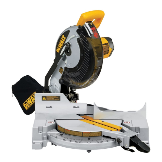
Dw703 (120 volt) 10" compound miter saw
Hide thumbs
Also See for DW703:
- User manual ,
- Instruction manual (52 pages) ,
- Quick start manual (2 pages)
Table of Contents
Advertisement
Advertisement
Table of Contents

Related Manuals for DeWalt DW703


Summary of Contents for DeWalt DW703
- Page 2 WALT Industrial Tool Co., 701 East Joppa Road, Baltimore, MD 21286 NOV02-CD-1 Form No. 395465 DW702, DW703 Copyright 2000, 2003 The following are trademarks for one or more D WALT power tools: the yellow and black color scheme; the “D” shaped air intake grill; the array of pyramids on the handgrip; the kit box...
-
Page 3: Instruction Manual
IF YOU SHOULD EXPERIENCE A PROBLEM WITH YOUR DEWALT PURCHASE, CALL 1-800-4 DEWALT. Before returning this product call IN MOST CASES, A DEWALT REPRESENTATIVE CAN RESOLVE YOUR PROBLEM OVER THE PHONE. 1-800-4-D WALT IF YOU HAVE A SUGGESTION OR COMMENT, GIVE US A CALL. -
Page 4: Table Of Contents
Table of Contents DOUBLE INSULATION/POLARIZED PLUG INSTRUCTIONS ........1 OPERATION ..……………………………………………………………………………6 SAFETY INSTRUCTIONS FOR ALL TOOLS ..…………………………………………1 SWITCH ........................6 ADDITIONAL SAFETY RULES ..……………………………………………………….1 CUTTING WITH YOUR SAW ................6 ELECTRICAL CONNECTION ..…………………………………………………………2 CROSSCUTS ........................6 UNPACKING YOUR SAW ..……………………………………………………………2 BEVEL CUTS ........................6 FAMILIARIZATION ..………………………………………………………………………2 QUALITY OF CUT ......................6 SPECIFICATIONS..………………………………………………………………………2 BODY AND HAND POSITION ..................7... -
Page 5: Double Insulation/Polarized Plug Instructions
Important Safety Instructions • CHECK DAMAGED PARTS. Before further use of the tool, a guard or other part that is damaged should be carefully checked to determine that it will operate properly and perform its intended function—check for alignment of moving parts, binding of moving parts, WARNING: When using electric tools, basic safety precautions should always be breakage of parts, mounting and any other conditions that may affect its operation. -
Page 6: Electrical Connection
In addition to this instruction manual, the carton should contain: read and understood. 1. One No. DW703 miter saw with blade. CAUTION: Wear appropriate personal hearing protection during use. Under some 2. One blade wrench in wrench pocket shown in Fig. 4. - Page 7 Workstation provides fast, easy set up for material support and accurate measuring system. SAW BLADES: ALWAYS USE 10" SAW BLADES WITH 5/8" (16mm) ARBOR DW7082 HOLES. SPEED RATING MUST BE AT LEAST 5500 RPM. END PLATE DEWALT NO. OF BLADE APPLICATION TYPE OF CUT BLADE TEETH DESC.
-
Page 8: Stabilizer
Stabilizer FIG. 3 FIG. 1 TRIGGER CARRYING MOTOR SWITCH Your saw includes a stabilizer (Fig.2). This must be in HANDLE END CAP SPINDLE place and in contact with the work surface at all times LOCK while using your saw. This stabilizer is factory installed BUTTON BEVEL and needs no adjustment. -
Page 9: Transporting The Saw
position by the guard bracket screw. Depress the spindle assembly left or right until the blade is perpendicular to the FIG. 5 lock button with one hand and use the supplied blade fence, as measured with the square. Retighten the three wrench in the other hand to loosen (clockwise) the left screws. -
Page 10: Guard Actuation And Visibility
Operation close to the blade as practical to provide maximum FIG. 8 workpiece support, without interfering with arm up & Plug the saw into any household 60 Hz power source. down movement. Tighten knob securely. When the bevel Refer to the nameplate for voltage. Be sure the cord will operations are complete, don’t forget to relocate the not interfere with your work. -
Page 11: Body And Hand Position
When smoothest cuts are desired for molding and other CUTTING PICTURE FRAMES, SHADOW BOXES AND FIG. 11A OTHER FOUR SIDED PROJECTS precision work, a sharp (60 - 80 tooth carbide) blade and a slower, even cutting rate will produce the desired results. To best understand how to make the items listed here, we suggest that you try a few simple projects using scrap Ensure that material does not creep while cutting. -
Page 12: Miter Scale
(Figure 18) of your project and locate that angle on the decrease the miter angle when mitering to the right, move appropriate arc in the chart. From that point follow the chart the arm to align the appropriate vernier mark with the FIG. -
Page 13: Cutting Crown Molding
Right side 1 inch from the end of the board. Trying to cut more than FIG. 15 an inch will cause the saw’s gear case to interfere with 1. Position molding with bottom of the molding against the workpiece. If you want to cut base molding between the fence 3-1/2"... - Page 14 BEVEL SETTING TYPE OF CUT FIG. 15A FIG. 16 FIG. 17 LEFT SIDE, INSIDE CORNER: 33.85° 1. Top of molding against fence 2. Miter table set right 31.62° 3. Save left end of cut RIGHT SIDE, INSIDE CORNER: 33.85° 1. Bottom of molding against fence 2.
- Page 15 FIG. 25 FIG. 22 FENCE TABLE CROWN MOLDING FLAT ON TABLE AND AGAINST FENCE CENTER MARK ON VERNIER SCALE ALIGNS WITH DESIRED WHOLE ANGLE ON MITER SCALE (24° RIGHT MITER) FIG. 25A FIG. 23 BOTTOM SIDE OF MOLDING DW 7084 CROWN MOLDING FENCE TOP SIDE MOLDING...
-
Page 16: Special Cuts
Maintenance FIG. 27 INSIDE CORNER: 1. All bearings are sealed. They are lubricated for life Left side and need no further maintenance. 1. Miter right at 45° 2. Save the right side of cut 2. Periodically clean all dust and wood chips from around Right side AND UNDER the base and the rotary table. -
Page 17: Compound Miter Cut Reference Chart
TABLE 1: COMPOUND MITER CUT (POSITION WOOD WITH BROAD FLAT SIDE ON THE TABLE AND THE NARROW EDGE AGAINST THE FENCE) BEVEL DEGREE SETTING SET THIS BEVEL ANGLE ON SAW... -
Page 18: Troubleshooting Guide
Troubleshooting Guide BE SURE TO FOLLOW SAFETY RULES AND INSTRUCTIONS TROUBLE! SAW WILL NOT START WHAT’S WRONG? WHAT TO DO… 1. Saw not plugged in 1. Plug in saw 2. Fuse blown or circuit breaker tripped 2. Replace fuse or reset circuit breaker 3.