Mitsubishi Electric SUZ-KA25VA2 Technical & Service Manual
Split-type, heat pump air conditioners
Hide thumbs
Also See for SUZ-KA25VA2:
- Technical & service manual (12 pages) ,
- Operation manual (172 pages) ,
- Installation manual (14 pages)
Table of Contents
Advertisement
SPLIT-TYPE, HEAT PUMP AIR CONDITIONERS
TECHNICAL & SERVICE MANUAL
R410A
Outdoor unit
[Model names]
SUZ-KA25VA2
SUZ-KA35VA2
SUZ-KA50VA2
SUZ-KA60VA2
SUZ-KA71VA2
SUZ-KA25VA2.TH
SUZ-KA35VA2.TH
NOTE:
This service manual describes technical data of the
outdoor units.
RoHS compliant products have <G> mark on the spec
name plate.
For servicing of RoHS compliant products, refer to the
RoHS Parts List.
[Service Ref.]
SUZ-KA25VA2.TH
SUZ-KA35VA2.TH
SUZ-KA50VA2.TH
SUZ-KA60VA2.TH
SUZ-KA71VA2.TH
Indication of
model name
CONTENTS
2. TECHNICAL CHANGES .................................... 3
3. PART NAMES AND FUNCTIONS ...................... 6
4. SPECIFICATION ................................................. 7
5. NOISE CRITERIA CURVES ............................... 9
6. OUTLINES AND DIMENSIONS ........................ 10
7. WIRING DIAGRAM ........................................... 13
8. REFRIGERANT SYSTEM DIAGRAM .............. 17
9. ACTUATOR CONTROL .................................... 21
10. SERVICE FUNCTIONS ..................................... 22
11. TROUBLESHOOTING ...................................... 22
12. DISASSEMBLY INSTRUCTIONS ..................... 63
PARTS CATALOG (OCB472)
September 2011
No.OCH472
REVISED EDITION-A
HFC
utilized
R410A
Revision:
• Errors in "11.
TROUBLESHOOTING"
have been corrected in
REVISED EDITION-A.
• Some descriptions have
been modified.
• Please void OCH472.
Advertisement
Chapters
Table of Contents

Related Manuals for Mitsubishi Electric SUZ-KA25VA2


Summary of Contents for Mitsubishi Electric SUZ-KA25VA2
-
Page 1: Table Of Contents
R410A TECHNICAL & SERVICE MANUAL R410A Outdoor unit Revision: [Model names] [Service Ref.] • Errors in "11. TROUBLESHOOTING" SUZ-KA25VA2.TH have been corrected in SUZ-KA25VA2 REVISED EDITION-A. • Some descriptions have SUZ-KA35VA2.TH been modified. SUZ-KA35VA2 • Please void OCH472. SUZ-KA50VA2.TH SUZ-KA50VA2 SUZ-KA60VA2.TH... -
Page 2: Combination Of Indoor And Outdoor Units
COMBINATION OF INDOOR AND OUTDOOR UNITS 1-1. INDOOR UNIT SERVICE MANUAL Outdoor unit Indoor unit Heat pump type SUZ- Service Service Ref. KA25VA2.TH KA35VA2.TH KA50VA2.TH KA60VA2.TH KA71VA2.TH Manual No. — — — — SLZ-KA25VA(L).TH — — — SLZ-KA35VA(L).TH OC320 — —... -
Page 3: Technical Changes
TECHNICAL CHANGES INFORMATION FOR THE AIR CONDITIONER WITH R410A REFRIGERANT • This room air conditioner adopts an HFC refrigerant (R410A) which never destroys the ozone layer. • Pay particular attention to the following points, though the basic installation procedure is same as that for R22 conditioners. 1 As R410A has working pressure approximate 1.6 times as high as that of R22, some special tools and piping parts/ materials are required. - Page 4 Conversion chart of refrigerant temperature and pressure (MPa [Gauge]) R410A NOTE: The unit of pressure has been changed to MPa on the international system of units (SI unit system). The conversion factor is: 1 (MPa [Gauge]) =10.2 (kgf/cm [Gauge]) -0.5 -30 -20 -10 1.
- Page 5 2. Refrigerant piping 1 Specifications Use the refrigerant pipes that meet the following specifications. Outside diameter Wall thickness Pipe Insulation material 6.35 For liquid Heat resisting foam plastic 9.52 Specific gravity 0.045 Thickness 9.52 8 mm For gas 12.7 15.88 •...
-
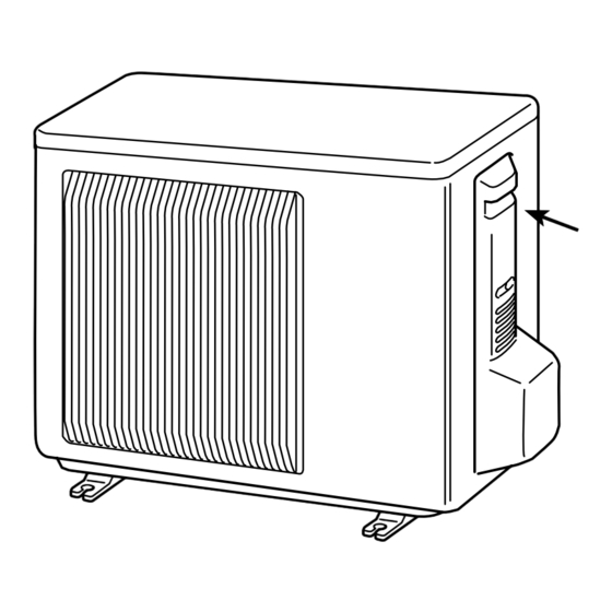
Page 6: Part Names And Functions
PART NAMES AND FUNCTIONS SUZ-KA25VA2.TH SUZ-KA35VA2.TH Air inlet (back and side) Piping Drain hose Air outlet Drain outlet SUZ-KA50VA2.TH SUZ-KA60VA2.TH Air inlet (back and side) Piping Drain hose Air outlet Drain outlet SUZ-KA71VA2.TH Air inlet (back and side) Piping Drain hose... -
Page 7: Specification
SPECIFICATION SUZ-KA35VA2.TH SUZ-KA50VA2.TH SUZ-KA60VA2.TH SUZ-KA71VA2.TH SUZ-KA25VA2.TH Outdoor Service Ref. Cooling Cooling Cooling Heating Cooling Heating Cooling Heating Function Heating Heating Single phase Single phase Single phase Single phase Single phase Power supply 230V, 50Hz 230V, 50Hz 230V, 50Hz 230V, 50Hz 230V, 50Hz 3.65... - Page 8 Specifications and rating conditions of main electric parts SUZ-KA25VA2.TH SUZ-KA35VA2.TH SUZ-KA50VA2.TH SUZ-KA60VA2.TH SUZ-KA71VA2.TH Model SUZ-KA25VA2. SUZ0KA35VA2. SUZ-KA50VA2. SUZ-KA60VA2. SUZ-KA71VA2. Item (CT) (CT1, 2) ETQ19Z68AY Current transformer (CT61) ETQ19Z53AY (CT761, CT781) (C61) 620+ 420V Smoothing (C62, C63) 620+ 420V capacitor (CB1, 2, 3) 560μF 450V...
-
Page 9: Noise Criteria Curves
NOISE CRITERIA CURVES SUZ-KA25VA2.TH SUZ-KA35VA2.TH FUNCTION SPL(dB(A)) FUNCTION SPL(dB(A)) FAN SPEED LINE FAN SPEED LINE COOLING COOLING High High Med. Med. HEATING HEATING Test conditions, Test conditions, Cooling : Dry-bulb temperature 35 Wet-bulb temperature (24 ) Cooling : Dry-bulb temperature 35... -
Page 10: Outlines And Dimensions
OUTLINES AND DIMENSIONS SUZ-KA25VA2.TH SUZ-KA35VA2.TH Unit: mm REQUIRED SPACE Basically open 100mm or more without any obstruction in front and on both sides of the unit. Drain hole 42 Air in Air in Open two sides of left, right, or rear side. - Page 11 SUZ-KA50VA2.TH SUZ-KA60VA2.TH Unit: mm REQUIRED SPACE Open as a rule Drain holes 500mm or more if the front and both sides are open 100mm or more Air in 200mm or more if 100mm or more there are obstacles to both sides Air in 4-Oval holes 10×21 Air out...
- Page 12 SUZ-KA71VA2.TH Unit: mm REQUIRED SPACE Open as a rule 500mm or more if the front and both sides are open 417.5 Air in 100mm or more 200mm or more if there are obstacles to both sides Air in Air out 2-Oval holes 10 21 Open as a rule 500mm or more if the back,...
-
Page 13: Wiring Diagram
WIRING DIAGRAM SUZ-KA25VA2.TH SUZ-KA35VA2.TH OCH472A... - Page 14 SUZ-KA50VA2.TH OCH472A...
- Page 15 SUZ-KA60VA2.TH OCH472A...
- Page 16 SUZ-KA71VA2.TH OCH472A...
-
Page 17: Refrigerant System Diagram
REFRIGERANT SYSTEM DIAGRAM SUZ-KA25VA2.TH Unit: mm Refrigerant pipe ø9.52 4-way valve (with heat insulator) Muffler Outdoor heat exchanger Stop valve temperature (with service port) thermistor Outdoor Muffler Discharge RT68 heat Flared connection exchanger temperature thermistor RT62 Ambient Compressor temperature thermistor... - Page 18 SUZ-KA50VA2.TH Unit: mm Muffler #100 4-way valve Refrigerant pipe ø12.7 (with heat insulator) Stop valve (with service port) Outdoor Flared connection Discharge heat Ambient temperature exchanger temperature thermistor Defrost thermistor RT62 thermistor RT65 RT61 Compressor Outdoor heat exchanger temperature thermistor RT68 Flared connection Strainer...
- Page 19 SUZ-KA71VA2.TH Unit: mm Muffler Refrigerant pipe ø 15.88 #100 4-way valve (with heat insulator) Stop valve (with service port) Outdoor Flared connection Discharge heat Ambient temperature exchanger temperature thermistor Defrost thermistor RT62 thermistor RT65 RT61 Compressor Outdoor heat exchanger temperature thermistor RT68 Flared connection...
- Page 20 SUZ-KA25VA2.TH SUZ-KA35VA2.TH SUZ-KA50VA2.TH SUZ-KA60VA2.TH SUZ-KA71VA2.TH MAX. REFRIGERANT PIPING LENGTH Refrigerant piping: m Piping size O.D: mm Models Max. Length A Max. Height difference B Liquid SUZ-KA25VA2.TH 9.52 SUZ-KA35VA2.TH 6.35 SUZ-KA50VA2.TH 12.7 SUZ-KA60VA2.TH 30(15) 15.88 SUZ-KA71VA2.TH 9.52 ( ): MFZ-KA50VA-E4 MAX. HEIGHT DIFFERENCE...
-
Page 21: Actuator Control
ACTUATOR CONTROL SUZ-KA25VA2.TH SUZ-KA35VA2.TH SUZ-KA50VA2.TH SUZ-KA60VA2.TH SUZ-KA71VA2.TH 9-1. Outdoor fan motor control The fan motor turns ON/OFF, interlocking with the compressor. [ON] The fan motor turns ON 5 seconds before the compressor starts up. [OFF] The fan motor turns OFF 15 seconds after the compressor has stopped running. -
Page 22: Service Functions
SERVICE FUNCTIONS SUZ-KA25VA2.TH SUZ-KA35VA2.TH CHANGE IN DEFROST SETTING <JS> When the JS wire of the outdoor Inverter P.C. board is cut/ soldered, the defrost finish temperature is changed. (Refer to 11-6-1) Defrost fi nish temperature Jumper wire SUZ-KA25VA2.TH SUZ-KA35VA2.TH soldered... -
Page 23: Failure Mode Recall Function
11-2. Failure mode recall function As this air conditioner has a function to memorize all the failures that had happened, the latest failure detail can be recalled by following the procedures below. Use this function when the check code is not displayed with wired remote controller or the remote controller at use is wireless type. -
Page 24: Continuous
11-2-2. Wired remote controller CHECK button Turn on the power. Refrigerant address Press the [CHECK] button twice. TEMP. button Set refrigerant address with [TEMP] button IC: Indoor unit if system control is used. OC: Outdoor unit Press the [ON/OFF] button to stop the self-check. °C °C SIMPLE... -
Page 25: Continuous
11-2-4. Outdoor unit failure mode table SUZ-KA25VA2.TH SUZ-KA35VA2.TH SUZ-KA50VA2.TH Abnormal point LED indication Condition Correspondence (Failure mode/protection) (Outdoor P.C. board) — — — Outdoor power system Overcurrent protection stop is continuously • Reconnect connectors. performed 3 times within 1 minute after •... -
Page 26: Heating
SUZ-KA60VA2.TH Outdoor LED indication Abnormal point Details of abnormal Detecting method Check point (Failure mode) LED1 LED2 Outdoor thermistors Discharge temperature When a short circuit is detected in the • Check the outdoor thermistors. Lighting Once thermistor during operation, or when an thermistor open circuit is detected in the thermistor after 10 minutes of compressor start-up. -
Page 27: Continuous
SUZ-KA71VA2.TH Abnormal point LED indication Condition Correspondence (Failure mode / protection) (Outdoor P.C. board) None (Normal) — — — Outdoor power system Overcurrent protection stop is continuously • Reconnect connectors. Refer to 11-5. a"How to check inverter/ performed 3 times within 1 minute after the •... -
Page 28: Continuous
11-3. Trouble shooting check table SUZ-KA25VA2.TH SUZ-KA35VA2.TH SUZ-KA50VA2.TH Abnormal point/ Con- Symptom LED indication dition Outdoor unit 1-time flash every Outdoor power sys- Overcurrent protection stop is continuously performed 3 times • Reconnect connector of compres- does not oper- 2.5 seconds within 1 minute after the compressor gets started, or failure of sor. -
Page 29: Cooling
SUZ-KA60VA2.TH Indication Symptom Abnormal point/Condition Condition Correspondence LED1 (Red) LED2 (Yellow) Outdoor unit • Check the connection of the compressor connecting When IPM protection stop or lock protection stop is continuously does not wire. operate. performed three times within 1 minute after the compressor gets started, •... -
Page 30: Heating
SUZ-KA60VA2.TH Indication Symptom Abnormal point/Condition Condition Correspondence LED1 (Red) LED2 (Yellow) These symptoms do not mean any abnormality Outdoor unit Primary current protection When the input current exceeds 15A. Once Lighting operates. of the product, but check the following points. Secondary current protection When the current of the compressor •... -
Page 31: Continuous
SUZ-KA71VA2.TH Abnormal point/ Symptom LED indication Condition Correspondence Condition Outdoor unit 1-time fl ash every Outdoor power sys- Overcurrent protection stop is continuously performed 3 times • Reconnect connector of compres- does not op- 2.5 seconds within 1 minute after the compressor gets started. sor. - Page 32 11-4. Trouble criterion of main parts (1) SUZ-KA25VA2.TH SUZ-KA35VA2.TH Part name Check method and criterion Figure Defrost thermistor (RT61) Fin temperature Measure the resistance using a tester. thermistor (RT64) Ambient temperature Refer to 11-6. “Test point diagram and voltage”, 11-6-1.
- Page 33 11-4. Trouble criterion of main parts (2) SUZ-KA50VA2.TH SUZ-KA60VA2.TH SUZ-KA71VA2.TH Part name Check method and criterion Figure Defrost thermistor Measure the resistance using a tester. (RT61) Fin temperature Refer to 11-6. “Test point diagram and voltage”, 11-6-4. “Outdoor thermistor (RT64) electronic control P.C.
-
Page 34: Continuous
[SUZ-KA25/35/50VA2.TH] 11-5. Troubleshooting flow A How to check inverter/compressor Disconnect the connector between compressor and the intelligent power module (IPM). “Check of open phase”. Check the voltage between terminals. Replace the inverter P.C. board. Are the voltages balanced? Check the compressor. “Check of compressor”. - Page 35 [SUZ-KA25/35/50VA2.TH] D Check of compressor winding Disconnect the connector between the compressor and intelligent power module, and measure the resistance between the compressor terminals. <<Measurement point>> at 3 points BLK-WHT Measure the resistance between the lead wires at 3 points. BLK-RED WHT-RED <<Judgement>>...
- Page 36 [SUZ-KA25/35/50VA2.TH] G Check of R.V. coil First of all, measure the resistance of R.V. coil to check if the coil is defective. Refer to 11-4. In case CN721 is not connected or R.V. coil is open, voltage is generated between the terminal pins of the connector although any signal is not being transmitted to R.V.
- Page 37 [SUZ-KA25/35/50VA2.TH] I Check of power supply 280 - 370 VDC DB61 Disconnect the connector (CN61) between compressor and intelligent power module. Rectify indoor/outdoor Turn ON power supply and press connecting wire. EMERGENCY OPERATION switch. Inverter P.C. board (Solder side) Is there voltage 230 VAC Replace the indoor Does the left lamp of OPERATION between the indoor terminal...
- Page 38 [SUZ-KA25/35/50VA2.TH] J Check of LEV (For wired remote controller use model) Start Turn on power supply to the outdoor unit after checking Normal LEV coil is fi xed to the LEV body securely. Is "click - click" sound heard? Or, do you feel vibration of the LEV coil with a hand? Disconnect the connector CN724 is there nor- Replace the inverter P.C.
- Page 39 [SUZ-KA25/35/50VA2.TH] L How to check miswiring and serial signal error (For wireless remote controller use model) Turn OFF the power supply. Is there rated voltage in the Check the power supply. power supply? Turn ON the power supply. Is there rated voltage between outdoor termi- Check the wiring.
- Page 40 [SUZ-KA25/35/50VA2.TH] L How to check miswiring and serial signal error (For wired remote controller use model) Turn OFF the power supply. Is there rated voltage in the Check the power supply. power supply? Turn ON the power supply. Is there rated voltage between outdoor termi- Check the wiring.
- Page 41 [SUZ-KA25/35/50/60VA2.TH] Electromagnetic noise enters into TV sets or radios Is the unit earthed? Earth the unit. Is the distance between the antennas Extend the distance between the antennas and and the indoor unit within 3 m, or is the the indoor unit, and/or the antennas and the distance between the antennas and the outdoor unit.
- Page 42 [SUZ-KA60VA2.TH] Outdoor unit does not operate. (LED display: display OFF) Check of power supply Start Check the connecting of parts of main power supply circuit. Turn on power supply. Is there voltage of 230V AC in the Check the power supply cable. power supply terminal block? Replace the noise Is the output voltage from the noise...
- Page 43 [SUZ-KA60VA2.TH] When unit cannot operate neither by the remote controller nor by EMERGENCY OPERATION switch. Indoor unit does not operate. Outdoor unit does not operate. How to check miswiring and serial signal error (when outdoor unit does not work) (For wireless remote controller use model) As for indoor unit.
-
Page 44: Outdoor Unit Does Not Operate
[SUZ-KA60VA2.TH] When unit cannot operate neither by the remote controller. Indoor unit does not operate. Outdoor unit does not operate. How to check miswiring and serial signal error (when outdoor unit does not work) (For wired remote controller use model) As for indoor unit. - Page 45 [SUZ-KA60VA2.TH] The cooling operation or heating operation does not operate. (LED display: Both LED1 and LED2 lighting) Check of R.V. coil • When heating operation does not work. 1. Disconnect the lead wire leading to the compressor. 2. 3 minutes after turning on the power supply, start EMERGENCY OPERATION in HEAT mode.
- Page 46 [SUZ-KA60VA2.TH] When cooling, heat exchanger of non-operating indoor unit frosts. When heating, non-operating indoor unit get warm. LED display: LED1 LED2 Check of LEV Lighting Lighting 6 time Goes out Turn on power supply to the outdoor unit after checking LEV coil is mounted to the LEV body securely.
- Page 47 [SUZ-KA60VA2.TH] When thermistor is abnormal. Check of outdoor thermistors Disconnect the connector in the outdoor electronic control P.C. board or the outdoor power board Replace the thermistor. (see below table), and measure the resistance of thermistor. Is the thermistor normal? Reconnect the connector CN661 on the outdoor electronic control P.C.
- Page 48 [SUZ-KA60VA2.TH] When the operation frequency does not go up from lowest frequency. Check of HPS 1. Disconnect the connector CN681 in the electronic control P.C. board. 2. Check the resistance of HPS after 1 minutes have passed since the outdoor unit power supply was turned off. Infinity Check the resistance between Replace HPS.
-
Page 49: Continuous
[SUZ-KA71VA2.TH] a How to check inverter/compressor Disconnect the connector between compressor and the intelligent power module (IPM). Check the voltage between terminals. See 11-5. “Check of open phase”. Replace the inverter P.C. board. Are the voltages balanced? See 11-5. D “Check of compressor”. Check the compressor. - Page 50 [SUZ-KA71VA2.TH] d Check of compressor winding ●Disconnect the connector between the compressor and intelligent power module, and measure the resistance between the compressor terminals. <<Measurement point>> at 3 points BLK-WHT Measure the resistance between the lead wires at 3 points. BLK-RED WHT-RED <<Judgement>>...
- Page 51 [SUZ-KA71VA2.TH] g Check of outdoor thermistors Disconnect the connector of thermistor in the outdoor P.C. board (see below table), and measure the resistance of thermistor. Replace the thermistor except RT64. Is the resistance of thermistor normal? When RT64 is abnormal, replace the inverter P.C. (Refer to 11-6-3.) board.
- Page 52 [SUZ-KA71VA2.TH] i Check of outdoor fan motor Disconnect the connectors CN931 and CN932 from the inverter P.C. board. Check the connection between the connector CN931 and CN932. Is the resistance between each ter- minal of outdoor fan motor normal? (Refer to 11-4.) Disconnect CN932 from the inverter P.C.
- Page 53 [SUZ-KA71VA2.TH] k Check of LEV (For wireless remote controller use model) Turn ON the power supply. <Preparation of the remote controller> While pressing both OPERATION SELECT button and TOO COOL button on the remote controller at the same time, press RESET button. First, release RESET button.
- Page 54 [SUZ-KA71VA2.TH] l Check of inverter P.C. board Check the outdoor fan motor. (Refer to 11-5.i.) Is the fuse (F901) blown on the in- verter P.C. board? Check the connection of the connectors (CN931, CN932) of the outdoor fan motor. If the connection is poor, make it correct. Operate the outdoor unit by starting EMERGENCY OPERATION.
- Page 55 [SUZ-KA71VA2.TH] m How to check miswiring and serial signal error Turn OFF the power supply. Is there rated voltage in the power supply? Check the power supply. Turn ON the power supply. Is there rated voltage between outdoor terminal block S1 and S2? Check the wiring.
- Page 56 [SUZ-KA71VA2.TH] n Electromagnetic noise enters into TV sets or radios Is the unit earthed? Earth the unit. Is the distance between the antennas Extend the distance between the antennas and and the indoor unit within 3 m, or is the the indoor unit, and/or the antennas and the distance between the antennas and the outdoor unit.
- Page 57 11-6. Test point diagram and voltage 11-6-1. Inverter P.C. board SUZ-KA25VA2.TH SUZ-KA35VA2.TH Smoothing Smoothing Smoothing capacitor capacitor capacitor Fuse (F701) DB61 Back side of unit (C62) (C63) (C61) 250 V 3.15 A DC 260 - 300 V Fuse (F801) AC 230 V 250 V 3.15 A...
- Page 58 11-6-2. Inverter P.C. board SUZ-KA50VA2.TH Smoothing Smoothing Smoothing R.V.coil capacitor capacitor capacitor Fuse (F701) (CN721) DB61 Back side of unit (C62) (C63) (C61) 250 V 3.15 A 230 VAC DC 260 ~300 V Fuse (F801) AC 230 V 250 V 3.15 A Fuse (F901) 250 V 3.15 A Output to...
- Page 59 11-6-3. Inverter P.C. board SUZ-KA71VA2.TH Fuse (F62) Fuse (F601) R.V. coil (CN602) T2.0AL250V T3.15AL250V 230VAC Jumper wire for changing defrost setting (JS) Jumper wire for pre-heat control setting (JK) Signal of out- Defrost thermistor door fan motor /RT61 (CN671) (CN931) Discharge temperature thermistor/RT62 (CN671)
- Page 60 11-6-4. Outdoor electronic control P.C. board SUZ-KA60VA2.TH Defrost thermistor (RT61) Ambient temperature thermistor (RT65) Discharge temperature thermistor (RT62) Outdoor heat exchanger temperature thermistor (RT68) 100 110 120 Temperature ( ) Temperature ( ) Fin temperature thermistor (RT64) 10 20 30 40 50 60 70 80 Temperature ( ) LED 1 LED 2...
- Page 61 11-6-5. Noise filter P.C. board SUZ-KA60VA2.TH CN901 To electronic CN902 CN903 control To power To power P.C. board board board 230V AC 50Hz Input CN912 R.V. coil 230V AC 230V 230V AC AC 50Hz 50Hz Output Output NR64 VARISTOR F64 FUSE F911 FUSE 2A/250V 1A/250V...
- Page 62 11-6-6. Outdoor power board SUZ-KA60VA2.TH Connect to the compressor Voltage among phases: 5V to 180V 325-370V DC Connect to the earth Output (Red) Connect to the controller board (–) (+)1-5(–): Signal transmission (To electronic control P.C. board) (White) 5V DC pulse wave (+)2-5(–): Zero cross signal : Not used (+)6-5(–): 15V...
-
Page 63: Disassembly Instructions
Pull the terminal while pull out the terminal pushing the locking slowly. Locking lever lever. Connector SUZ-KA25VA2.TH SUZ-KA35VA2.TH OUTDOOR UNIT NOTE: Turn OFF power supply before disassembling. 1. Removing the cabinet Photo 1 (1) Remove the screw fixing the service panel. - Page 64 OPERATING PROCEDURE PHOTOS 2. Removing the inverter assembly, inverter P.C. board Photo 3 (1) Remove the cabinet and panels. (Refer to 1.) (2) Disconnect the lead wire to the reactor and the following con- Screws of the nectors: relay panel <Inverter P.C.
- Page 65 OPERATING PROCEDURE PHOTOS 5. Removing outdoor fan motor Photo 6 (1) Remove the cabinet and panels. (Refer to 1.) Outdoor heat (2) Disconnect the following connectors: exchanger tempera- <Inverter P.C. board> ture thermistor CN932 (Fan motor) (3) Remove the propeller nut. (Photo 7) (4) Remove the propeller.
- Page 66 SUZ-KA50VA2.TH SUZ-KA60VA2.TH NOTE: Turn OFF power supply before disassembling. OPERATING PROCEDURE PHOTOS 1. Removing the cabinet Photo 1 Screw of the top panel (1) Remove the screws of the service panel. (2) Remove the screws of the top panel. (3) Remove the screw of the valve cover. (4) Remove the service panel.
- Page 67 OPERATING PROCEDURE PHOTOS 2. Removing the inverter assembly, inverter P.C. board Photo 4 and power board Screws of the power board assembly (for SUZ-KA50VA2.TH) (1) Remove the top panel, cabinet, service panel and back panel. (Refer to 1.) (2) Disconnect the lead wire to the reactor and the following connectors;...
- Page 68 OPERATING PROCEDURE PHOTOS 4. Removing the defrost thermistor, discharge temper- Photo 7 ature thermistor, outdoor heat exchanger tempera- Discharge temperature thermistor ture thermistor and ambient temperature thermistor (1) Remove the top panel, cabinet and service panel. (Refer to 1.) (2) Remove the back panel. (Refer to 1.) (3) Remove the inverter assembly.
- Page 69 OPERATING PROCEDURE PHOTOS 6. Removing the compressor and 4-way valve Photo 10 (1) Remove the top panel, cabinet and service panel. (Refer to 1.) (2) Remove the back panel. (Refer to 1.) (3) Remove the inverter assembly. (Refer to 2.) (4) Recover gas from the refrigerant circuit.
- Page 70 SUZ-KA71VA2.TH NOTE: Turn OFF power supply before disassembling. OPERATING PROCEDURE PHOTOS 1. Removing the cabinet Photo 1 (1) Remove the screws of the service panel. Screws of the top panel (2) Remove the screws of the top panel. (3) Remove the screw of the valve cover. (4) Remove the service panel.
- Page 71 OPERATING PROCEDURE PHOTOS 2. Removing the inverter assembly, inverter P.C. board Photo 3 Screw of the (1) Remove the cabinet and panels. (Refer to 1.) relay panel (2) Disconnect the lead wire to the reactor and the following con- Screws of the nectors: PB support Earth wires...
- Page 72 OPERATING PROCEDURE PHOTOS 4. Removing the discharge temperature thermistor, Photo 5 defrost thermistor, outdoor heat exchanger tempera- Outdoor heat Ambient tem- perature exchanger tempera- ture thermistor and ambient temperature thermistor ture thermistor thermistor (1) Remove the cabinet and panels. (Refer to 1.) (2) Disconnect the lead wire to the reactor and the following connectors: <Inverter P.C.
- Page 73 OCH472A...
- Page 74 HEAD OFFICE: TOKYO BLDG., 2-7-3, MARUNOUCHI, CHIYODA-KU, TOKYO100-8310, JAPAN cCopyright 2010 MITSUBISHI ELECTRIC ENGINEERING CO.,LTD Distributed in Sep. 2011 No.OCH472 REVISED EDITION-A New publication, effective Sep. 2011 Distributed in May. 2010 No.OCH472 PDF 4 Specifications subject to change without notice...