Table of Contents
Advertisement
Quick Links
Advertisement
Table of Contents

Related Manuals for Monogram ZDP486NDPSS


Summary of Contents for Monogram ZDP486NDPSS
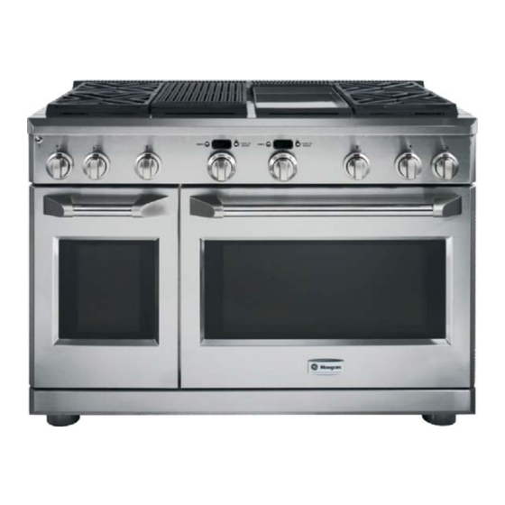
- Page 1 Monogram Professional Range ®...
- Page 2 IMPORTANT SAFETY NOTICE The information in this presentation is intended for use by individuals possessing adequate backgrounds of electrical, electronic, & mechanical experience. Any attempt to repair a major appliance may result in personal injury & property damage. The manufacturer or seller cannot be responsible for the interpretation of this information, nor can it assume any liability in connection with its use.
- Page 3 GE Factory Service Employees are required to use safety glasses with side shields, cut resistant (Dyneema®) gloves & steel toe shoes for all repairs. Plano Safety Glasses Steel Toe Shoes Dyneema® Cut Resistant Glove Prescription Safety Glasses Safety Glasses must be compliant with ANSI Z87.1-2003...
- Page 4 Pro Range Models ZDP486NDPSS ZDP486NRPSS ZDP484NGPSS ZDP486LDPSS ZDP484LGPSS ZDP486LRPSS ZDP364NRPSS ZDP366NPSS ZDP304NPSS ZDP364NDPSS ZDP364LRPSS ZDP366LPSS ZDP304LPSS ZDP364LDPSS...
-
Page 5: Burner Configurations
Burner Configurations... - Page 6 Pro Range Nomenclature...
- Page 7 Pro Range Model Location The model tag is located under the front control panel on the left side. The model and serial number is also located behind the left front knob on the bezel.
-
Page 8: Mini-Manual Location
Mini-Manual Location The mini-manual is located at the bottom behind the access panel... - Page 9 Optional Backsplash Kits Backsplashes are available 36” with adjustable height shelf in 30”, 36” and 48” widths 12” height...
- Page 10 Pro Range Sales Demo Kit Pub Number 24-M488 Activates all lights and control displays 120V applied to L1 and L2 (note jumper L2-N)
- Page 11 New “Rangetop” Models ZGU364NRPSS ZGU366NPSS ZGU364NDPSS ZGU364LRPSS ZGU366LPSS ZGU364LDPSS ZGU486NDPSS ZGU486NRPSS ZGU484NGPSS ZGU486LDPSS ZGU486LRPSS ZGU484LGPSS...
- Page 12 Rangetop Nomenclature...
- Page 13 Rangetop Model Location The model tag is located under the cooktop. The model and serial number is also located behind the left front knob on the bezel.
- Page 14 Mini-Manual Location Mini-Manual...
- Page 15 Optional Black Knob Kits Pro Range Models – Part Number Pro Range Models – Part Number ZDP304N/LPSS - WB03K10268 ZDP366N/LPSS - WB03K10269 ZDP364N/LRPSS - WB03K10270 ZDP364N/LDPSS - WB03K10271 ZDP484N/LGPSS - WB03K10272 ZDP486N/LRPSS - WB03K10273 ZDP486N/LDPSS - WB03K10274 Rangetop Models – Part Number Rangetop Models –...
-
Page 16: Supplied Power Cords
Supplied Power Cords 48” Range – 50 amp 30” & 36” Range – 30 amp 115V – 15 amp... - Page 17 Range Gas Conversion Grill Griddle Each model is shipped with the appropriate gas conversion kit and instructions.
- Page 18 Rangetop Gas Conversion Conversion Instructions Orifice Kit...
-
Page 19: Warranty
Warranty year warranty Parts and labor year warranty Parts and labor year limited warranty Gas burners year limited warranty Gas burners (parts only) (parts only) (Grill and griddle burners not included) (Grill and griddle burners not included) Limited lifetime warranty Oven racks Limited lifetime warranty... - Page 20 ZDP484NGPSS...
-
Page 22: Control Panel Lighting
Control Panel Lighting LED lighting on all models. On/Off switch on panel. -
Page 23: Oven Control Features
Oven Control Features Electronic dial control. The larger outer bezel or dial controls the cooking mode, while the center dial knob controls temperature. A red font indicates a A green font indicates a temperature setting. timer or display setting. - Page 24 Self Clean Features On double oven models, the ovens can be set to self clean in sequence. The first oven set starts the cycle. Cleaning defaults to 5 hours, but can be adjusted between 3 to 5 hours in 15 minute increments. The control will display “End”...
- Page 25 On double oven models, one oven can be used for cooking functions while the other oven is cleaning (not recommended for Proof Cycle). All range top functions – surface burners, grill and griddle can be used while cleaning.
- Page 26 All oven racks, surface burner wok grates (not the grate frame), the griddle vent trim and the grill grate (not the grate frame) can be cleaned in the self-clean cycle. The grease troughs cannot.
- Page 27 Rack Ladders Correct Incorrect The rack ladders can be installed incorrectly, which will cause the oven racks to be located at the wrong height. Make certain the mounting bracket is located at the top, as shown above.
-
Page 28: Special Features
Special Features Oven thermostat adjustment (displayed as OFFSEt) and Sabbath mode (displayed as SAbbAth) can be accessed through the Special Features control. Press and hold both the Timer and the Push to Select knobs on the main oven for approximately 4 seconds. The display will show SF. -
Page 29: Offset Mode
Offset Mode Temperature can be offset by +/- 35°F in 1°F increments. The adjustment will only affect Bake, Convection Bake and Convection Roast. It does not affect broiling or self-cleaning temperatures. The adjustment will be retained in memory after a power failure. The large oven control changes the setting in both ovens. -
Page 30: Sabbath Mode
Sabbath Mode Sabbath mode can be used for baking only. When the Sabbath feature is set, the oven lights, convection fan and all audible beeps will be disabled. The feature will also provide a random delay period, of approximately 30 seconds to 1 minute, before the oven will turn on once it is set to BAKE. - Page 31 Proof Cycle The display will scroll “too hot” The Proof cycle maintains a 95°F above 125°F and start the Proof oven temperature by cycling the cycle only when the oven cools halogen oven lights. below that set point. Note: Proof is the only cycle where the inner knob does not need to be set.
-
Page 32: Leveling System
Leveling System Shipped with legs up Outer sleeve covers leg All 4 legs are adjustable... - Page 33 Toe Kick Covers Front Legs If toe kick is installed, pull to remove for access to front leveling legs...
- Page 34 Built-In Leveling Leg Wrench...
- Page 35 Accessing the Rear Leveling Legs Two Phillips screws and a tab at each end secure the rear grill...
- Page 36 Rods at the rear of the range run from the top down to the leveling screw 1/4” hex head at top of rod Lower end attached to leveling leg...
- Page 38 Gas Shutoff The gas shutoff can be accessed from the front by removing the top rear grill.
-
Page 39: Surface Burners
Surface Burners Defendi surface burners All are electronic re-ignition The lower flame simmer setting is approximately 140°F. All burners on the 36” and 48” are 18K BTU output. The 30” model has one 18K and three 10K BTU burners. - Page 40 Five T15 Torx screws mount the surface burner. 3 coarse thread screws on the outside. Main Orifice Simmer Orifice 2 fine thread screws on the inside. Both orifices are 7mm High altitude kit: WB28K10553...
- Page 41 High Altitude Surface Burner Operation Although a high altitude kit is available for elevations above 3000 feet, the surface burners on the Monogram Range and Rangetop are designed to perform satisfactorily at elevations up to 6000 feet. At higher elevations, the gas burners MAY exhibit the following operating characteristics due to the thinner air.
- Page 42 If only one burner is affected, check the burner for a blocked or misaligned orifice. Step 1. Examine the orifice and make sure it is drilled on center and is free of debris or burrs. Step 2. Check for misalignment of an orifice mount by removing the burner head and cap and placing a 7mm nutdriver or socket with extension over the orifice to exaggerate any misalignment.
- Page 44 Surface Burner Pan Removal The burner pan must be removed to access the spark module, transformer and surface burner tubing...
-
Page 45: Control Panel Removal
Control Panel Removal To remove the front control panel, remove surface burner grates and knobs, grill knob, griddle knob and bezel. Remove the Phillips screws within the bezel attached to the manifold brackets. Remove the T15 Torx screws from the bottom of the panel. Remove the screw at each corner on the top of the panel near the surface burner pans. - Page 46 Heat reflecting barrier Transformer Spark Module...
-
Page 47: Spark Module
Spark Module 2 Phillips screws mount the spark module... - Page 48 A Phillips screw secures the connector plug...
-
Page 49: Surface Burner Valve And Switch
Surface Burner Valve and Switch... - Page 50 Inside View of Switch For training purpose only – switch is not repairable...
- Page 51 Surface Burner Circuit...
- Page 52 Griddle Bamboo cutting board 304 Stainless steel with aluminum substrate for fast and even heat 200°F to 450°F Stainless Steel Aluminum...
-
Page 53: Seasoning The Griddle
Seasoning the Griddle Before a new griddle is used, it must be seasoned to prevent permanent discoloration and staining. 1. Clean the griddle thoroughly with hot, soapy water to remove any protective coating. 2. Wipe the surface using a solution of 1 quart water and 1 cup white vinegar. - Page 54 Griddle Leveling Screws Clamping Screws Rear view of griddle Loosen inner clamping screws to adjust outer griddle leveling screws. The griddle should be level or tilted slightly towards the front.
- Page 55 Removing the Griddle Front of Range Push the griddle towards the back of the range to release tabs...
- Page 56 The griddle capillary is clamped to the underside of the griddle...
- Page 57 18K BTU Griddle Burner Griddle removed for easy access to burner components...
- Page 58 Griddle Burner Removal Two ¼” hex head screws at the rear secure the griddle burner...
- Page 59 Igniter Removing the burner mounting screws allows access to the ¼” hex head igniter screws and the igniter harness connector...
-
Page 60: Safety Valve
Safety Valve The front control panel must be lowered to remove the griddle base pan. Removing the base pan provides access to the safety valve. The valve is secured with two nuts from the front of the frame. - Page 61 Griddle Thermostat and Switch Lower the front control panel to gain access to the griddle thermostat and LED switch...
- Page 62 The thermostat and switch are mounted to the manifold bracket by two long Phillips screws. It’s a very tight fit between the bracket and the front frame of the range.
- Page 63 The thermostat and switch assembly separate into several sections...
-
Page 64: Griddle Circuit
Griddle Circuit... - Page 65 Grill The grill is reversible depending upon the food being cooked. The grooved side of the grill allows juices and grease to flow towards the front grease trough. Used for foods such as steaks or hamburgers. The flat side of the grill is used for delicate foods such as vegetables or seafood.
- Page 66 The grill grate can be self-cleaned The grate frame should not be self-cleaned...
- Page 67 The stainless steel grill baffle is designed to help reduce flare-ups. The baffle rests on 4 support posts located on the side walls...
- Page 68 The glow bar igniter can be tested at this point. Current should be between 3.4 – 3.6 amps. Resistance should be 45 to 400 ohms.
- Page 69 Two Phillips screws hold the reflector trim in place. The screen lifts off the burner once the trim and igniter are removed.
- Page 70 The 14K BTU ceramic IR (infrared) burner is mounted with four ¼” hex head screws.
- Page 71 The IR (infrared) burner is replaced as an assembly.
- Page 72 Remove the spring clip to access the connector.
- Page 73 Valve resistance should be 1 ohm or less. Grill safety valve also uses the longer of the two orifices.
- Page 74 Front switch controls igniter. Rear switch controls LED indicator.
- Page 75 Switch mounting bracket is a part of the valve assembly.
- Page 76 Grill Circuit...
- Page 77 Control Panel Lighting The front control panel must be lowered to access the LED light assemblies and power supply...
-
Page 78: Power Supply
Power Supply The LED power supply is located above the surface burner manifold on the left side of the control area... - Page 79 Power Supply Connection LED Output Connection Light Switch Connection...
-
Page 80: Led Assembly
LED Assembly If one LED assembly fails or a wiring connection is loose, all LEDs will be out. - Page 81 LED Mounting A specific resistor is used based on the number of LEDs on each model. Loosening the Phillips screw allows the LED to slide along the channel attached to the back of the front panel.
- Page 82 Control Lighting Circuit ZDP484 model shown...
-
Page 83: Oven Components
Oven Components Oven Mode Selector Temperature Knob BAKE 175º to 550°F CONV BAKE 175º to 550°F CONVECTION ROAST 175º to 550°F CONVECTION BROIL HIGH or LOW BROIL BROIL HIGH or LOW BROIL CLEAN CLEAN PROOF... -
Page 84: Oven Control Logic Board
Oven Control Logic Board A front panel logic board controls oven operation through user input and feedback from the oven sensor and switches... - Page 85 The logic board is currently available only as a complete assembly.
- Page 86 Sensor connections Meat probe connections LIN bus connection...
-
Page 87: Oven Relay Board
Oven Relay Board The oven relay board is located below the oven cavity and is accessed by removing a bottom panel and lowering the board to the floor. - Page 88 The panel beneath the range is held in place with three ¼” hex head screws at the front and tabs at the rear. The relay board is mounted to the panel.
- Page 89 There is sufficient wiring to pull the relay board our completely for service. The board will not have enough clearance to slide out if the front leveling legs are in their lowest position.
- Page 90 The majority of the connections are color coded to match the wiring...
- Page 92 The small oven relay board is accessed in the same method.
- Page 93 Preheat Circuit...
-
Page 94: Bake Element
Bake Element True Hidden Bake... - Page 95 Bake Element Testing MAIN COMPANION...
- Page 96 Bake Element Replacement Remove the two T15 Torx screws to lower the bake element shelf. Use CAUTION as the shelf is heavy and will drop down once the screws are removed.
- Page 97 Remove the ¼” hex head screw on the left end of the cover plate...
- Page 98 Slide the cover plate to the left to disengage the tab...
- Page 99 Carefully remove the center section of insulation...
- Page 100 Note the position of the wiring harness through the opening in the bottom of the shelf and the surrounding gasket...
- Page 101 Slide the element assembly out for replacement...
- Page 102 Bake Circuit...
-
Page 103: Broil Element
Broil Element The broil cycle is closed door only. The display will scroll “CLOSE door” if the door is left open in the broil cycle. If the door is not closed within 60 seconds, the broil cycle will shut off and display “End”. - Page 104 BROIL #1 BROIL #2...
- Page 105 Wiring is very tight, but the broil element can be tested and replaced from inside the oven cavity...
- Page 106 Broil Circuit...
-
Page 107: Convection Element
Convection Element CONVECTION #1 CONVECTION #2... - Page 108 The convection element can be tested and replaced from the inside the oven cavity...
-
Page 109: Convection Fan
Convection Fan... -
Page 110: Convection Fan Removal
Convection Fan Removal... -
Page 111: Oven Sensor
Oven Sensor... -
Page 112: Cooling Fan
Cooling Fan The cooling fan is located on the back of the oven and vents through the rear grill. The fan runs at low speed once the oven reaches 200°F in all cooking modes. It operates immediately at high speed in self-clean as soon as the door is locked. -
Page 113: Sail Switch
Sail Switch The sail switch provides feedback of cooling fan operation. If the sail switch is open when the fan should be on, the logic board will disable power to all cooking elements. -
Page 114: Lock Motor Assembly
Lock Motor Assembly Door Unlock Door Switch Lock Switch Door Status Switch... - Page 115 If the lock motor fails during a self-clean cycle, there is sufficient space between the oven door and control panel to remove the 2 Phillips screws holding the lock motor assembly. Carefully opening the door will pull the lock motor assembly out far enough to service.
- Page 116 Lock Motor Circuit...
-
Page 117: Factory Test Mode
Factory Test Mode The Factory Test mode can be accessed within the first 2 minutes of power up, before any other selections are made. Press and hold the Push To Select knob for approximately 3 seconds within the first 2 minutes. The display will show “Prod” The options for Factory Test are cycled through by pressing the Timer button. - Page 118 Step Sequence time Action 0.0 seconds Wait 2.0 seconds Turn on Bake 1 Element 4.0 seconds Turn off Bake 1 Element and wait Component sequence when 5 Seconds Turn on Bake 2 Element 7 seconds Turn off Bake 2 Element and wait 8 seconds Turn on Broil 1 Element Factory Test mode starts.
- Page 119 Pressing the Timer button scrolls through the available tests. press displays ROM revision press displays EEPROM checksum press displays Probe temperature press displays oven temperature press displays all red LED segments...
- Page 120 press displays all green LED segments press displays EEPROM programming press displays F-Codes 7 fault codes are stored in memory 6 communication faults are stored...
- Page 121 F Codes...
- Page 122 Miswire Detection A miswire error is detected if any of the power supply lines (L1, L2 or N) are wired incorrectly or not present. If detected, the control will beep continuously and scroll “Bad LinE” across available displays (main and companion oven, if applicable).