Table of Contents
Advertisement
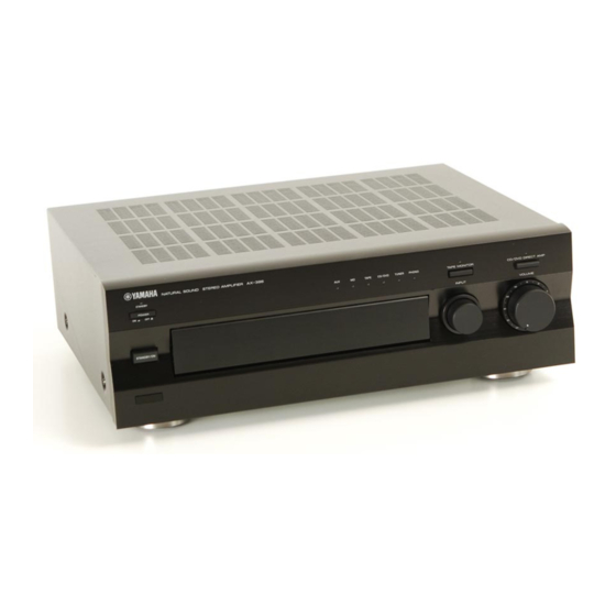
AX-496/396
I CONTENTS
.......................................................... 1
............................................. 2
............................................................ 3
.............................................................. 3
........................................................... 6
1 0 0 7 0 2
This manual has been provided for the use of authorized YAMAHA Retailers and their service personnel.
It has been assumed that basic service procedures inherent to the industry, and more specifically YAMAHA Products,
are already known and understood by the users, and have therefore not been restated.
WARNING:
Failure to follow appropriate service and safety procedures when servicing this product may result
in personal injury, destruction of expensive components, and failure of the product to perform as
specified. For these reasons, we advise all YAMAHA product owners that any service required
should be performed by an authorized YAMAHA Retailer or the appointed service representative.
IMPORTANT:
The presentation or sale of this manual to any individual or firm does not constitute authorization,
certification or recognition of any applicable technical capabilities, or establish a principle-agent
relationship of any form.
The data provided is believed to be accurate and applicable to the unit(s) indicated on the cover. The research,
engineering, and service departments of YAMAHA are continually striving to improve YAMAHA products.
Modifications are, therefore, inevitable and specifications are subject to change without notice or obligation to
retrofit. Should any discrepancy appear to exist, please contact the distributor's Service Division.
WARNING:
Static discharges can destroy expensive components. Discharge any static electricity your body
may have accumulated by grounding yourself to the ground buss in the unit (heavy gauge black
wires connect to this buss).
IMPORTANT:
Turn the unit OFF during disassembly and part replacement. Recheck all work before you apply
power to the unit.
.......................................... 2
........................................ 2
................................... 6
STEREO AMPLIFIER
SERVICE MANUAL
IMPORTANT NOTICE
............................................................. 7
......................................................... 8
µ
................................................................. 9
........................................ 26~29
........................................................... 30~47
AX-496/396
.................................. 10~25
........................ 48
P.O.Box 1, Hamamatsu, Japan
Advertisement
Chapters
Table of Contents

Related Manuals for Yamaha AX-496


Summary of Contents for Yamaha AX-496
-
Page 1: Table Of Contents
This manual has been provided for the use of authorized YAMAHA Retailers and their service personnel. It has been assumed that basic service procedures inherent to the industry, and more specifically YAMAHA Products, are already known and understood by the users, and have therefore not been restated. -
Page 2: Specifications
AX-396 60W+60W B, G models AC230V, 50Hz Maximum Output Power (EIAJ) Power Consumption 1kHz, 10% THD AX-496 Approx. 210W AX-496 8Ω/6Ω 130W / 150W AX-396 Approx. 150W AX-396 6Ω 110W AC Outlets (Switched) Dynamic Power (IHF) R, T, G models 100W Max x 3 8/6/4/2Ω... -
Page 3: To Service Personnel
AX-496/396 I TO SERVICE PERSONNEL 1. Critical Components Information. AC LEAKAGE Components having special characteristics are marked s WALL EQUIPMENT TESTER OR and must be replaced with parts having specifications equal OUTLET UNDER TEST EQUIVALENT to those originally installed. 2. Leakage Current Measurement (For 120V Models Only). -
Page 4: Front Panels
AX-496/396 I FRONT PANELS MAX-496 MAX-396 I REAR PANELS (AX-496) R model... - Page 5 AX-496/396 T model B model G model I REAR PANELS (AX-396) R model...
- Page 6 AX-496/396 A model B model G model J model...
-
Page 7: Internal View
AX-496/396 I INTERNAL VIEW 1 AX-496: MAIN P.C.B. (6) / AX-396: MAIN P.C.B. (7) 2 MAIN P.C.B. (2) 3 MAIN P.C.B. (1) 4 MAIN P.C.B. (3) 5 FUNCTION P.C.B. (4) 6 FUNCTION P.C.B. (5) 7 MAIN P.C.B. (9) 8 MAIN P.C.B. (8) 9 FUNCTION P.C.B. -
Page 8: Adjustments
AX-496/396 I ADJUSTMENTS Confirmation of Idling Current • Right after Power is switched ON, confirm the voltages measures at R553 (L ch) and R561 (R ch) are between 0.1mV to 10mV. • If it exceeds 10mV, open (cut off) R552 (L ch), R560 (R ch) and reconfirm the voltage. -
Page 9: Block Diagram
AX-496/396 I BLOCK DIAGRAM M AX-496 CD DIRECT AMP CD DIRECT AMP CD DIRECT AMP PURE DIRECT POWER AMP 10dB LOUDNESS SP A 10dB BALANCE –10dB TONE CONTROL 33.5dB SP B PHONO EQ AMP PHONES MOTOR AUDIO PHONO DRIVER MUTE... -
Page 10: Μ -Com Data
VRUP Motor Volume (UP) VRDN Motor Volume (DOWN) RYPS Power Relay Rotary Encoder (Right) Rotary Encoder (Left) D34/5 AX-496, 396/596 Detect H: 496, 396 L: 596 Rec Out Selector Detect PRDC Protection (DC) Protection (Overload) PRPS Protection (Power Supply) Vref... -
Page 11: Printed Circuit Board
AX-496/396 AX-496 I PRINTED CIRCUIT BOARD (Foil side) P.C.B. MAIN (3) P.C.B. MAIN (1) To FUNCTION (1) SPEAKERS IMPEDANCE SELECTOR To FUNCTION (7) RYSP To MAIN (6) -
Page 12: P.c.b.
AX-496/396 AX-496 I PRINTED CIRCUIT BOARD (Foil side) P.C.B. MAIN (5) (R, T models) To MAIN (4) To MAIN (2) P.C.B. MAIN (2) To MAIN (9) To MAIN (8) (B, G models) To MAIN (5) (R, T models) POWER TRANSFORMER P.C.B. -
Page 13: P.c.b
AX-496/396 AX-496 I PRINTED CIRCUIT BOARD (Foil side) P.C.B. FUNCTION (6) To MAIN (1) To FUNCTION (4) P.C.B. FUNCTION (1) To FUNCTION (1) PRPS RYPS RYSP To MAIN (1) BASS TREBLE BALANCE LOUDNESS To FUNCTION (8) To FUNCTION (6) P.C.B. FUNCTION (3) - Page 14 AX-496/396 AX-496 I PRINTED CIRCUIT BOARD (Foil side) P.C.B. FUNCTION (9) P.C.B. FUNCTION (7) P.C.B. FUNCTION (4) To FUNCTION (5) To MAIN (1) To FUNCTION (8) TUNER STANDBY/ON TAPE DATA CDDL CDDR SPEAKERS PHONES P.C.B. FUNCTION (8) To FUNCTION (9)
-
Page 15: P.c.b
AX-496/396 AX-396 I PRINTED CIRCUIT BOARD (Foil side) P.C.B. MAIN (3) P.C.B. MAIN (1) To FUNCTION (1) SPEAKERS IMPEDANCE SELECTOR To FUNCTION (7) RYSP To MAIN (6) -
Page 16: P.c.b
AX-496/396 AX-396 I PRINTED CIRCUIT BOARD (Foil side) P.C.B. MAIN (5) (R model) To MAIN (4) To MAIN (2) P.C.B. MAIN (2) To MAIN (9) To MAIN (8) (A, B, G models) To MAIN (5) (R model) POWER TRANSFORMER P.C.B. MAIN (7) - Page 17 AX-496/396 AX-396 I PRINTED CIRCUIT BOARD (Foil side) P.C.B. FUNCTION (6) To MAIN (1) To FUNCTION (4) P.C.B. FUNCTION (1) To FUNCTION (1) PRPS RYPS RYSP To MAIN (1) BASS TREBLE BALANCE LOUDNESS To FUNCTION (8) To FUNCTION (6) P.C.B. FUNCTION (3)
- Page 18 AX-496/396 AX-396 I PRINTED CIRCUIT BOARD (Foil side) P.C.B. FUNCTION (9) To FUNCTION (5) P.C.B. FUNCTION (7) P.C.B. FUNCTION (4) To MAIN (1) To FUNCTION (8) TUNER STANDBY/ON TAPE DATA P.C.B. FUNCTION (10) CDDL CDDR To FUNCTION (8) SPEAKERS PHONES POWER P.C.B.
-
Page 19: Schematic Diagram
AX-496 SCHEMATIC DIAGRAM AX-496 PHONO EQ AMP 12.6 To MAIN (1) see page 27 TONE CONTROL AMP 14.3 14.2 14.3 -12.7 14.2 -0.1 -14.3 -0.1 CD BUFFER -14.3 -14.2 VOLUME AMP CD/DVD DIRECT AMP & PURE DIRECT OFF -14.3 PROTECTION 14.6... - Page 20 AX-496 SCHEMATIC DIAGRAM AX-496 POWER 12.8 12.8 AC12.6 POWER SUPPLY RELAY DRIVER IMPEDANCE SELECTOR 42.9 POWER SUPPLY From FUNCTION (7) 23.6 23.6 42.9 AC78.0 see page 26 50.1 15.2 18.4 43.1 18.3 15.8 15.8 -18.3 -50.0 -15.8 -15.8 -15.2 -18.3...
- Page 21 AX-396 SCHEMATIC DIAGRAM AX-396 PHONO EQ AMP -0.8 4.8 12.5 To MAIN (1) see page 29 TONE CONTROL AMP 14.4 14.3 14.4 -12.5 15.3 14.2 -14.3 CD BUFFER -14.3 -14.2 VOLUME AMP CD/DVD DIRECT -14.1 AMP OFF PROTECTION 14.6 -1.3 -4.9 14.6 -1.0...
- Page 22 AX-396 SCHEMATIC DIAGRAM AX-396 POWER 11.5 11.5 13.7 13.7 AC13.8 12.1 13.7 12.7 12.7 POWER SUPPLY IMPEDANCE SELECTOR RELAY DRIVER POWER SUPPLY 37.9 From FUNCTION (7) 24.5 24.5 37.2 AC72.0(AC59.6) see page 26 46.5(38.5) 15.3 31.2 37.2 34.0 15.9 15.9 -33.6 -46.4 (-38.4)
-
Page 23: Parts List
AX-496/396 I WARNING PARTS LIST Components having special characteristics are marked s and must be replaced with parts having specifications equal to those originally in- stalled. I ELECTRICAL PARTS Carbon resistors (1/6W or 1/4W) are not included in the ELECTRICAL PARTS List. - Page 24 AX-496/396 AX-496 V5012200 P.C.B. MAIN(RT) C550 FG644100 C.CE 0.01uF V5012300 P.C.B. MAIN(B) C551 UA954100 C.MYLAR 0.01uF V5012400 P.C.B. MAIN(G) C552 UA954100 C.MYLAR 0.01uF CB501 Vi878900 CN.BS.PIN C553 UA954100 C.MYLAR 0.01uF CB502 Vi878400 CN.BS.PIN C554 UA954100 C.MYLAR 0.01uF CB503 VK024700 CN.BS.PIN C555 UA954100 C.MYLAR...
- Page 25 AX-496/396 AX-496 Q516 iA097030 2SA970 GR,BL s TE501 V4746500 OUTLET.AC 3P(RT) Q517 iA097030 2SA970 GR,BL s TE501 VU543300 OUTLET.AC 1P(B) * s Q518 VE198700 TR 2SA1145 O,Y TE502 V4811400 TERM.SP 8P(BG) Q519 iC224030 2SC2240 GR,BL TE502 VC313700 TERM.SP 8P(RT) s Q520 iP011600 TR.PAIR...
- Page 26 AX-496/396 AX-496 C143 UR838100 C.EL 100uF C215 UA954100 C.MYLAR 0.01uF C144 UR838100 C.EL 100uF D101 VM974200 DIODE.ZENR HZS5C2TD 5.0V 01 C145 VJ599100 C.CE.TUBLR 0.1uF D102 VR711500 LED(or) SLR-325DC C146 UN866100 C.EL D103 VR711500 LED(or) SLR-325DC C147 UA953220 C.MYLAR 2200pF 50V...
- Page 27 AX-496/396 AX-496 SW108 VV523900 SW.PUSH PBS-YM-001 U101 VU591000 L.DTCT GP1U271X VR101 V4915000 VR.MTR A100KΩ VR103 VP700700 VR A100KΩ VR105 VP742000 VR MN100KΩ VR106 VP741800 VR B20KΩ VR107 VP741900 VR G25KΩ XL101 VE906000 RSNR.CE 4MHz ✻ New Parts ✻ New Parts...
- Page 28 AX-496/396 AX-396 V5011700 P.C.B. MAIN(J) C548 VS745400 C.POL.MTL 0.1uF 100V V5011800 P.C.B. MAIN(R) C549 FG644100 C.CE 0.01uF V5011900 P.C.B. MAIN(A) C550 FG644100 C.CE 0.01uF V5012000 P.C.B. MAIN(B) C551 UA954100 C.MYLAR 0.01uF 50V(ABG) 01 V5012100 P.C.B. MAIN(G) C552 UA954100 C.MYLAR 0.01uF...
- Page 29 AX-496/396 AX-396 Q513 iC1815I0 2SC1815 Y SW502 VA961800 VOLT.SELCT ESE-37247-F(R) s Q514 iA1015I0 2SA1015 Y * s SW503 V4466400 SW.PUSH SDKLA1-AP1 TV-5 * s Q515 VE198800 TR 2SC2705 O,Y s T501 XV442A00 TRANS.PWR Q516 iA097030 2SA970 GR,BL s T501 XV445A00 TRANS.PWR...
- Page 30 AX-496/396 AX-396 C130 VG287200 C.EL 10uF C200 UR837470 C.EL 47uF C131 VG287600 C.EL 100uF C201 UR837470 C.EL 47uF C132 VG287800 C.EL 330uF C203 FG644100 C.CE 0.01uF C133 VG287800 C.EL 330uF C204 FG644100 C.CE 0.01uF C134 VG287600 C.EL 100uF C205 UA954100 C.MYLAR 0.01uF...
- Page 31 AX-496/396 AX-396 Q104 VG722000 TR.DGT DTC144ES Q105 iC1815I0 2SC1815 Y Q106 iA1015I0 2SA1015 Y Q107 VP872700 TR 2SC4488 S,T Q108 iA093320 2SA933S Q,R Q109 iA1015I0 2SA1015 Y Q110 VK432900 TR 2SD1915F S,T Q111 iC1815I0 2SC1815 Y Q112 iC1815I0 2SC1815 Y R151 VP940400 R.MTL.OXD...
- Page 32 AX-496/396 AX-396/496 AX-496 I EXPLODED VIEW (AX-496) 3-30 3-13 3-42 (10) 3-30 6 (6) 3-16 6 (1) 3-30 3-42 200-1 3-30 3-14 3-1-1 6 (2) 3-40 3-43 3-2-2 3-41 6 (11) 6 (3) 3-1-3 3-2-1 3-1-4 3-15 3-10 3-1-3 R,T models...
- Page 33 AX-496/396 I MECHANICAL PARTS AX-496 Ref. PART NO. Description Remarks Markets 1- 1 V4595400 FRONT PANEL 1- 1 V4595500 FRONT PANEL 1- 1 V4595600 FRONT PANEL 1- 2 V4598400 ESCUTCHON, 5/22 1- 3 V4598800 LENS, 6P 1- 4 V4598900 LENS, 1P...
- Page 34 AX-496/396 AX-496 Ref. PART NO. Description Remarks Markets * s 8 XY163A00 POWER TRANSFORMER (RT) V2438700 CORD STOPPER ’10P1 s 12 VN363700 POWER CORD ASS’Y s 12 VV437300 POWER CORD ASS’Y s 12 VZ542500 POWER CORD ASS’Y (RT) VU590000 BINDING TIE...
- Page 35 AX-496/396 AX-496 Ref. PART NO. Description Remarks Markets EP600830 BIND HEAD B-TITE SCREW FCRM3-BL VT669300 PW HEAD B-TITE SCREW 3x8-8 MFC2 VT669400 PW HEAD B-TITE SCREW 3x15-8 MFC2 V2728500 BIND HEAD S-TITE SCREW MFZN2-BL EP600250 BIND HEAD B-TITE SCREW ZMC2-Y...
- Page 36 AX-496/396 AX-396/496 AX-396 I EXPLODED VIEW (AX-396) 3-30 3-13 3-42 (10) 3-30 6 (6) 3-16 3-42 3-30 3-42 6 (1) 200-1 6 (12) 3-30 3-14 3-1-1 6 (2) 3-40 3-40 3-43 3-2-2 3-41 6 (11) 6 (3) 3-1-3 3-2-1 3-1-4...
- Page 37 AX-496/396 AX-396 Ref. PART NO. Description Remarks Markets Rank 1- 1 V4595700 FRONT PANEL 1- 1 V4595900 FRONT PANEL 1- 1 V4596000 FRONT PANEL 1- 2 V4598400 ESCUTCHON, 5/22 1- 3 V4598800 LENS, 6P 1- 4 V4598900 LENS, 1P 1- 5...
- Page 38 AX-496/396 AX-396 Ref. PART NO. Description Remarks Markets Rank V5011900 P.C.B. ASS’Y MAIN V5012000 P.C.B. ASS’Y MAIN V5012100 P.C.B. ASS’Y MAIN V5012500 P.C.B. ASS’Y FUNCTION * s 8 XU441B00 POWER TRANSFORMER * s 8 XU442C00 POWER TRANSFORMER XU443B00 POWER TRANSFORMER...
- Page 39 AX-496/396 AX-396 Ref. PART NO. Description Remarks Markets Rank V4597600 PLATE SIDE L V4597700 PLATE SIDE R V4597800 PLATE SIDE R V4597900 PLATE SIDE R VQ368500 PUSH RIVET P3545-B VU984400 RING V5247600 DAMPER AA627310 GROUND TERMINAL EG330030 BIND HEAD SCREW FCRM3-BL VN413300 BIND HEAD BONDING B-T.
-
Page 40: Parts List For Carbon Resistors
AX-496/396 Parts List for Carbon Resistors Value 1/4W Type Part No. 1/6W Type Part No. Value 1/4W Type Part No. 1/6W Type Part No. 1.0 Ω 3100 3100 10 kΩ 7100 7100 HJ35 HF85 HF45 HF45 1.8 Ω ❊ 3180 11 kΩ... -
Page 41: Remote Control Transmitter
AX-496/396 AX-396/496 I REMOTE CONTROL TRANSMITTER G SCHEMATIC DIAGRAM U1 JT7060-2 00 08 10 18 15 IR-LED R3 200K 01 0D 11 19 16 R2 180 02 0A 12 1A 06 2SD1781K 47uF/16V 1B 4F 3.64MHz 04 0C 14 STANDBY/ON... - Page 42 AX-396/496...