Troy-Bilt 26J Operator's Manual
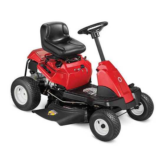
Mini-rider
Hide thumbs
Also See for 26J:
- Operator's manual (69 pages) ,
- Operation manual (72 pages) ,
- Operator's manual (68 pages)
Table of Contents
Advertisement
Safe Operation Practices • Set-Up • Operation • Maintenance • Service • Troubleshooting • Warranty
O
'
M
peratOr
s
anual
Lawn Tractor — 26J Mini-Rider
WARNING
READ AND FOLLOW ALL SAFETY RULES AND INSTRUCTIONS IN THIS MANUAL
BEFORE ATTEMPTING TO OPERATE THIS MACHINE.
FAILURE TO COMPLY WITH THESE INSTRUCTIONS MAY RESULT IN PERSONAL INJURY.
P. O. Box 1386, 97 KENT AVENUE, KITCHENER, ON N2G 4J1
Printed In USA
769-07604A
6.8.12
Advertisement
Table of Contents

Related Manuals for Troy-Bilt 26J


Summary of Contents for Troy-Bilt 26J
- Page 1 Safe Operation Practices • Set-Up • Operation • Maintenance • Service • Troubleshooting • Warranty ’ peratOr anual Lawn Tractor — 26J Mini-Rider WARNING READ AND FOLLOW ALL SAFETY RULES AND INSTRUCTIONS IN THIS MANUAL BEFORE ATTEMPTING TO OPERATE THIS MACHINE.
-
Page 2: Table Of Contents
To The Owner Thank You Thank you for purchasing your new equipment. It was carefully The manufacturer reserves the right to change product engineered to provide excellent performance when properly specifications, designs and equipment without notice and operated and maintained. without incurring obligation. -
Page 3: Safe Operation Practices
Important Safe Operation Practices WARNING: This symbol points out important safety instructions which, if not followed, could endanger the personal safety and/or property of yourself and others. Read and follow all instructions in this manual before attempting to operate this machine. Failure to comply with these instructions may result in personal injury. - Page 4 Mow only in daylight or good artificial light. Never carry passengers. Mow up and down slopes, not across. Exercise extreme caution when changing direction on slopes. Disengage blade(s) before shifting into reverse. Back up slowly. Always look down and behind before and while Watch for holes, ruts, bumps, rocks, or other hidden backing to avoid a back-over accident.
- Page 5 Be alert and turn machine off if a child enters the When practical, remove gas-powered equipment area. from the truck or trailer and refuel it on the ground. If this is not possible, then refuel such equipment on Before and while backing, look behind and down for a trailer with a portable container, rather than from a small children.
-
Page 6: Spark Arrestor
Do not modify engine Mower blades are sharp. Wrap the blade or wear gloves, and use extra caution when servicing them. To avoid serious injury or death, do not modify engine in any Keep all nuts, bolts, and screws tight to be sure the way. -
Page 7: Safety Symbols
Safety Symbols This page depicts and describes safety symbols that may appear on this product. Read, understand, and follow all instructions on the machine before attempting to assemble and operate. Symbol Description Symbol Description READ THE OPERATOR’S WARNING— SLOPE OPERATION MANUAL(S) Do not operate this machine on Read, understand, and follow... - Page 8 2 — i ection mportant peration racticeS...
-
Page 9: Assembly & Set-Up
Assembly & Set-Up Assembly & Set-Up Contents of Crate • One Riding Mower • One Seat Assembly • One Steering Pedestal Cap • One Steering Wheel/Shaft Assembly • One Rear Engine Cover • One Discharge Chute Assembly • One Rear Hitch Plate •... - Page 10 Figure 3-2 Figure 3-4 Slide the pedestal cap down onto the tractor (1) and clip Position the seat assembly over the seat mounting bracket, into place. Secure the pedestal with the hex screw (2) from aligning the holes provided. the hardware pack. See Figure 3-3. Install two shoulder bolts included with your hardware pack and secure with two lock nuts.
- Page 11 Installing The Deck Chute WARNING! NEVER operate this tractor without either the mulch plug or deck chute installed. Remove the wing knob installed on the mowing deck and retain for later installation. Install the deck chute assembly by inserting the two pegs on the bottom of the deck chute into the lock-holes on the mower deck.
- Page 12 Connecting the Battery Cables The recommended operating tire pressure is: • Approximately 10 psi for the rear tires CAlIFoRNIA PRoPoSITIoN 65 WARNING • Approximately 14 psi for the front tires Battery posts, terminals, and related accessories contain lead and lead compounds, chemicals known IMPoRTANT: Refer to the tire sidewall for exact tire to the State of California to cause cancer and...
-
Page 13: Controls & Features
Controls & Features Clutch/Brake Pedal Speed Control & Parking Brake Lever Fuel Level Indicator Ignition Switch Shift Lever Fuel Fill Cap Throttle/Choke Lever Deck Lift Lever Cup Holder PTO (Blade Engage) Lever Oil Fill Cap Figure 4-1 Lawn Tractor controls and features are illustrated in Fig 4-1 and described on the following pages. WARNING! Read and follow all safety rules and instructions in this manual, including the entire Operation section, before attempting to operate this machine. - Page 14 Throttle / Choke Control The throttle control lever is located on the left fender of the On/Lights tractor seated in the operator’s position, see Fig. 4-1. This lever controls the speed of the engine, as well as the choke when it Start is pushed all the way forward.
- Page 15 Speed Control Lever Deck Lift Lever The speed control lever, located on the right side of the tractor’s Found on your tractor’s right fender, the deck lift lever is used to steering console, allows you to regulate the ground speed of the change the height of the cutting deck.
-
Page 16: Operation
Operation Operation Swivel Seat WARNING This unit is equipped with a swivel seat feature, which aids the Avoid Serious Injury or Death operator in mounting and dismounting the unit. • Know location and function of all controls. Note: The seat must be facing forward in the operating position •... -
Page 17: Stopping The Engine
Engage the tractor’s parking brake. Activate the choke control. Turn the ignition key clockwise to the START position. After the engine starts, release the key. It will return to the ON position. IMPORTANT: Do NOT hold the key in the START position for longer than ten seconds at a time. -
Page 18: Engaging The Blades
The lawn tractor is brought to a stop by depressing the Move the throttle control lever to the FAST (rabbit) clutch-brake pedal. position. NOTE: When operating the unit initially, there will be little Grasp the PTO (Blade Engage) lever and pivot it all the way difference between the highest two speeds until after the belts forward into the engaged (ON) position. -
Page 19: Maintenance & Adjustment
Maintenance & Adjustments Maintenance Close the oil drain valve by rotating it clockwise, then reinstall the cap WARNING: Before performing any maintenance or Refill the engine with new motor oil as instructed in the repairs, disengage PTO, move shift lever into neutral Engine Owner’s Manual packed with your unit. - Page 20 Cleaning Battery Clean the battery by removing it from the tractor and washing with a baking soda and water solution. If necessary, scrape the battery terminals with a wire brush to remove deposits. Coat terminals and exposed wiring with grease or petroleum jelly to prevent corrosion.
-
Page 21: Seat Adjustment
• Approximately 14 psi for the front tires adjustment. See an authorized Troy-bilt Service Dealer to have IMPORTANT: Refer to the tire sidewall for exact tire your brakes properly adjusted. -
Page 22: Maintenance Schedule
If emptying the fuel system: • Remove the spark plug and pour one (1) ounce of engine oil through the spark plug hole into the • Do not drain fuel when the engine is hot. Allow the cylinder. Crank the engine several times to distribute engine adequate time to cool. -
Page 23: Service
Service Service Remove the remaining bow-tie cotter pins securing the Cutting Deck Removal deck to the unit, as shown in Fig. 7-3. To remove the cutting deck, proceed as follows: Place the PTO (Blade Engage) lever in the disengaged (OFF) position and engage the parking brake. - Page 24 Changing the Deck Belt NOTE: It is possible to change the deck belt with the cutting deck still installed on the tractor, however it is much easier to remove the deck first, change the deck belt, then reinstall the cutting deck. To change the cutting deck belt, proceed as follows: It is easiest to change the deck belt by first removing the cutting deck as instructed earlier in this section first.
-
Page 25: Cutting Blade
still installed on the tractor, first move the deck lift lever to CAUTION: If the jumper battery is installed on a its highest cutting position. vehicle (i.e. car, truck), do NOT start the vehicle’s Remove the mulch plug or bagging chute, if equipped, engine when jump starting your tractor. -
Page 26: Dealer
Changing the Transmission Drive Belt WARNING! If the cutting edge of the blade has previously been sharpened, or if any metal NOTE: Several components must be removed and special tools separation is present, replace the blades with new (i.e. air/impact wrench) in order to change the tractor’s drive belt. ones. -
Page 27: Troubleshooting
Troubleshooting Problem Cause Remedy Engine fails to start 1. PTO/Blade engaged. 1. Place knob (or lever) in disengaged (OFF) position. 2. Spark plug wire disconnected. 2. Connect wire to spark plug. 3. Fuel tank empty, or stale fuel. 3. Fill tank with clean, fresh (less than 30 days old) gas. -
Page 28: Attachments & Accessories
Attachments & Accessories The following attachments and accessories are compatible for Mini-Rider Lawn Tractors. See the retailer from which you purchased your tractor, an authorized MTD Service Dealer or phone (800) 800-7310 for information regarding price and availability. CAUTION: Lawn Tractors are NOT designed for use with any type of ground-engaging attachments (e.g. tiller The Mini-Rider or plow). -
Page 29: Replacement Parts
Replacement Parts Component Part Number and Description 954-04318 Drive Belt (Mowing Deck) 918-04822A Deck Spindle Cutting Blade (30”) 942-04385 925-1707D Battery Fuel Tank Cap 751-12179A 925-1745A Tire (Front) Not Serviceable 734-04641 Tire (Rear) 16 x 6.5 x 8 746-04829 Throttle Control/Cable 931-04633 Discharge Chute Assembly NOTE: Download a complete Parts Manual free of charge at www.mtdproducts.com or phone (800) 668-1238 to purchase a Parts... -
Page 30: Emission Control Warranty Statement
FEDERAL and/or CALIFORNIA EMISSION CONTROL WARRANTY STATEMENT YOUR WARRANTY RIGHTS AND OBLIGATIONS MTD Consumer Group Inc, the United States Environmental Protection Agency (EPA), and, for those products certified for sale in the state of California, the California Air Resources Board (CARB) are pleased to explain the emission (evaporative and/or exhaust) control system (ECS) warranty on your outdoor 2006 and later small off-road spark-ignited engine and equipment (outdoor equipment engine) In California, new outdoor equipment engines must be designed, built and equipped to meet the State’s stringent anti-smog standards (in other states, 1997 and later model year equipment must be designed, built, and equipped to meet the U.S. - Page 31 6. The outdoor equipment engine owner will not be charged for diagnostic labor that is directly associated with diagnosis of a defec- tive, emission-related warranted part, provided that such diagnostic work is performed at a warranty station. 7. MTD Consumer Group Inc is liable for damages to other engine or equipment components proximately caused by a failure under warranty of any warranted part.
-
Page 32: Warranty
FOUR YEAR SUPREME WARRANTY: For four years from date of retail purchase within Canada, MTD PRODUCTS LIMITED will, at its option, repair or replace, for the original purchaser, free of charge, any part or parts found to be defective in material or workmanship.