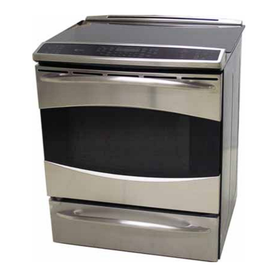
GE Profile PHS925ST1SS Technical Service Manual
30-in. slide-in induction and radiant ranges
Hide thumbs
Also See for Profile PHS925ST1SS:
- Owner's manual (92 pages) ,
- Installation instructions (2 pages)

Related Manuals for GE Profile PHS925ST1SS


Summary of Contents for GE Profile PHS925ST1SS
- Page 1 GE Appliances Technical Service Guide December 2011 Profi le 30-in. Slide-in Induction and Radiant Ranges PHS925ST1SS PS978ST1SS 31-9219 GE Appliances General Electric Company Louisville, Kentucky 40225...
- Page 2 If grounding wires, screws, straps, clips, nuts, or washers used to complete a path to ground are removed for service, they must be returned to their original position and properly fastened. GE Appliances Technical Service Guide Copyright © 2011 All rights reserved. This service guide may not be reproduced in whole or in part in any form without written permission from the General Electric Company.
-
Page 3: Table Of Contents
Table of Contents Aluminum Plate ................................66 Bake Element ..................................48 Bake Thermal Switch ..............................65 Blower Assembly ................................64 Bridge Board ..................................66 Broil Element ..................................44 Circuit Boards Connector Locator Views .......................16 Clean Thermal Switch ..............................65 Component Locator Views ............................7 Control Panel ..................................29 Convection Element .................................46 Convection Fan Assembly ............................47 Convection Fan Cover ..............................46... -
Page 4: Introduction
Introduction Model PHS925 The Profi le 30-in. Slide-In Induction Range with convection oven and warming drawer features electronic oven and induction element controls. The induction elements provide unmatched cooking performance and fl exibility. Induction technology heats only the pan and its contents and offers energy effi ciency by reducing wasted heat when compared to radiant and gas cooktops. - Page 5 Model PS785 GE's Profi le 30-in. Slide-In Radiant Range utilizes 2 ovens with convection cooking in the lower oven. This range features electronic oven and surface unit controls that combine modern digital technology with ease of operation. The superior style and performance parallel many commercial ranges.
-
Page 6: Nomenclature
Nomenclature Model Number P H S 9 2 5 S T 1 S S Product Color SS = Stainless Steel Brand P = Profi le Indicator for Engineering Confi guration and Product Service Only H = Induction 30" Slide-In Model Year Designator Feature Pack Designates features–the higher Model/Door Color... -
Page 7: Component Locator Views
Component Locator Views Front View - PHS925 Induction Cooktop Control Panel Oven Warming Drawer Front View - PS978 Radiant Cooktop Control Panel Upper Oven Lower Oven (Continued next page) – 7 –... - Page 8 Oven and Warming Drawer - Front View - PHS925 Door Lock Meat Probe Outlet Door Switch Light Broil Element Oven Temperature Sensor Convection Fan and Element Hidden Bake Element Warming Drawer Element Shown with oven door and warming drawer removed (Continued next page) –...
- Page 9 Upper and Lower Oven - Front View - PS978 Door Lock Door Switch Broil Element Light Light Oven Temperature Sensor Hidden Bake Element Meat Probe Outlet Door Lock Door Switch Broil Element Smoke Eliminator Light Oven Temperature Sensor Convection Fan and Element Hidden Bake Element Shown with oven doors removed (Continued next page)
- Page 10 Control Panel - PHS925 Display Board Main Logic Board Display Board Main Top - PHS925 Induction Module Hot Surface Indicator Light Assembly Hi Limit Thermostat Cooling Fan Fan Apparency Device (FAD) (Continued next page) – 10 –...
- Page 11 Control Panel - PS978 Main Logic Board Display Board Display Board Main Top - PS978 Bake Thermal Switch Clean Thermal Switch (Continued next page) – 11 –...
- Page 12 Cooktop Induction Elements - PHS925 Induction Element Warming Element Induction Element Induction Element Induction Element Bridge Board Induction Module - PHS925 Cooling Fan Filter Board Right Generator Board Left Generator Board (Continued next page) – 12 –...
- Page 13 Cooktop Radiant Elements - PS978 Tri-Ring Element Left Front Element Hot Surface Indicator Light Assembly Dual 5 & 8 Inch 240 Volt 12-Inch Tri-Ring 1100 Watts 240 Volt 2400 Watts 3000 Watts "Power Boil" 6" - 1050 Watts 9" - 900 Watts 12"...
- Page 14 Rear View - PHS925 Oven Temperature Sensor Broil Element Convection Element Convection Fan Motor (RPSM) Relay Daughter Relay Module (DRM) Power Supply Module Convection Fan Motor Capacitor Warming Drawer Element Note: The oven bake element terminals are located behind the left side panel. (Continued next page) –...
- Page 15 Rear View - PS978 Upper Oven Upper Oven Broil Element Temperature Sensor Upper Oven Door Lock Assembly RPSM (Relay Power Supply Module) AUX Board Oven Vent Tube RPSM (Relay Power Supply Module) Main Board Lower Oven Broil Element Lower Oven Door Lock Assembly Lower Oven Temperature Sensor Convection Element...
-
Page 16: Circuit Boards Connector Locator Views
Circuit Boards Connector Locator Views Relay Power Supply Module - PHS925 J7 - Door Lock Motor, Cooling Fan, Jumper Wire K8 to K1, Warming Drawer Element, Neutral, Oven Light, Convection Fan Motor Direction J10 - Ground J11 - Neutral Standby J14 - L1 J15 - RPSM to DRM Communication J16 - Oven Lock Switch, Oven Unlock Switch, FAD... - Page 17 Daughter Relay Module - PHS925 J15 - RPSM to DRM Communication J23 and J24 - Warming Zone Connections K17 - Warming Zone Main Logic Board - PHS925 and PS978 J841 J821 J501 J241 J502 J201 J851 J201 - Model Selector J241 - LINbus J501 - Oven Sensor, Meat Probe (PHS925), Upper Oven Sensor (PS978) J502 - Lower Oven Temperature Sensor, Meat Probe (PS978)
- Page 18 Relay Power Supply Module MAIN - PS978 J7 - Blower, Convection Fan, Door Lock Motor (Upper), Oven Lights, Door Switches J10 - Cabinet Ground J11 - Neutral J14 - L1 J15 - Communications J16 - Lock Switches J17 - Communications J20 - L1 and L2 J21 - Neutral K1 - Convection Fan Motor Direction...
- Page 19 Relay Power Supply Module AUX - PS978 J2 - RF Inner Element J3 - L1 J5 - LR Element J6 - L1 J7 - RF Center, RF Outer, CR, LF Inner, and LF Outer Elements Elements J14 - L1 J15 - Communications J17 - Communications K1 - LF Inner Element K2 -...
- Page 20 Daughter Relay Module 1 - PS978 J6 - Convection Fan, L1, and Lower Door Lock Motor J15 - Communications J23 - L1 J24 - Convection Fan K1 - Outer Broil (Lower) K3 - Upper Bake and Upper Broil Elements K7 - Double Line Break for Upper Bake, Upper Broil, and Upper Broil Boost Elements and Upper Broil Boost Elements K12 - Lower Door Lock Motor...
-
Page 21: Oven Door Assembly
Range Components 5. Lift door up until the hinge arms are clear of the WARNING: Sharp edges may be exposed when slots. servicing. Use caution to avoid injury. Wear Kevlar gloves or equivalent protection. Note: Combined Phillips-head/square-drive recess screws may be utilized on this appliance. Either Phillips or square-drive screwdrivers can be used to extract or install these screws. - Page 22 To remove the inner door assembly: To replace the inner door assembly: 1. Remove the door. See previous page. 1. Remove the inner door assembly. (See To remove the inner door assembly, this section.) 2. Place the door assembly, gasket side up, on a protective surface.
- Page 23 4. Remove the six 1/4-in. hex-head screws that Air enters the door assembly through large slots in attach the heat barrier to the inner door. the bottom and fl ows upward between the inner Remove the heat barrier. and outer assemblies, exhausting through slots in the top of the door.
- Page 24 On PHS925, the bottom center clip joins both ends To replace the outer door assembly on PHS925: of the gasket to form a continuous seal. Make sure 1. Remove the inner door assembly. (See To this clip is inserted into the bottom center hole in the remove the inner door assembly, this section.) inner door panel.
- Page 25 6. Slide the bottom trim and the glass out of the To replace the outer door assembly on PS978: outer door frame. Remove the four 1/4-in. hex-head screws that hold the inner heat shield and door handle to the outer door assembly.
- Page 26 To remove the upper oven door assembly on 5. Lift the door up until it is clear of the door PS978: hinges. Caution: The door is heavy. Use the correct lifting 6. Pull on the hinge arms lightly to relieve pressure procedure.
- Page 27 4. Remove the T-15 Torx screw from each side of 5. Remove the six 1/4-in. hex-head screws (3 from the outer door panel. each side) that attach the handle to the outer door assembly. 5. Separate the outer door assembly from the inner door.
-
Page 28: Warming Drawer Assembly
To replace the inner door assembly of the upper 5. Remove the insulation and the inner glass oven door on PS978: assembly from the inner door. 1. Remove the upper oven door outer door assembly. (See To remove the outer door assembly of the upper oven door on PS978, this section.) Inner Glass Assembly... -
Page 29: Control Panel
Control Panel Main Logic Board The control panel contains the main logic board and The main logic board is located inside the control panel. The main logic board is held to the control the glass touch controls. panel with two 1/4-in. hex-head screws on the right To remove the control panel: side and 2 tabs on the left side. -
Page 30: Cooktop Assembly
Cooktop Assembly Glass Touch Panel To remove the cooktop assembly on PHS925: The glass touch panel is attached to the control panel with two 1/4-in. hex-head screws at the 1. Disconnect power to the range. bottom and 2 tabs located at the top. 2. - Page 31 5. Remove the four 1/4-in. hex-head screws (2 on 9. Disconnect the 3 wire harnesses and ground each side) that attach the front of the cooktop wire that connect the induction module to the frame to the range. range wiring. 10.
-
Page 32: Rear Cover
To remove the rear cover on PS978: Rear Cover 1. Disconnect power to the range. To remove the rear cover on PHS925: 2. Pull the range out from its installation. 1. Disconnect power to the range. 3. Remove the hidden screw from the bottom of he 2. -
Page 33: Left Side Panel
8. Remove the three 1/4-in hex-head screws from Left Side Panel the top front of the control panel support. It is necessary to remove the left side panel to replace the bake element, hinge receiver, and upper oven liner. To remove the left side panel on PHS925: 1. - Page 34 10. Remove 1/4-in hex-head screw that attaches 12. Remove the two 1/4-in hex-head screws from the back of the extension brace to the range. the back of the side panel. 11. Carefully lift the left side of the control panel support, slide the extension brace forward and remove the extension brace from the range.
- Page 35 Note: The front of the panel is held to the range To remove the left side panel on PS978: frame by 3 plastic grommets that engage 3 keyhole It is necessary to remove the left side panel to slots placed along the inside front fl ange of the replace the bake element, hinge receiver, and upper panel.
- Page 36 4. Remove the 2 clips and insulation strip from the 7. Carefully lift the left side of the control panel top of the extension brace. support, slide the extension brace forward, and remove the extension brace from the range. 5. Remove the four 1/4-in. hex-head screws from the extension brace.
-
Page 37: Right Side Panel
9. Remove the three 1/4-in hex-head screws from Right Side Panel the top of the side panel. It is necessary to remove the right side panel to replace the hinge receiver and upper oven liner. To remove the right side panel on PSH925: 1. - Page 38 8. Remove the cooling blower. (See 12. Remove 1/4-in hex-head screw that attaches Cooling Fan and the back of the extension brace to the range. FAD (Fan Apparency Device) 9. Remove the two 1/4-in hex-head screws from the top front of the control panel support. 10.
- Page 39 14. Remove the two 1/4-in hex-head screws from Note: The front of the panel is held to the range the back of the side panel. frame by 3 plastic grommets that engage 3 keyhole slots placed along the inside front fl ange of the panel.
-
Page 40: Oven Door Hinge Receiver
To remove the lower oven door hinge receiver on Oven Door Hinge Receiver PS978: To remove the hinge receiver on PHS925: 1. Remove the side panel. (See Left Side Panel Right Side Panel 1. Remove the side panel. (See Left Side Panel Right Side Panel 2. -
Page 41: Oven Components
Oven Components To remove the RPSM Main Board on PS978: Relay Power Supply Module (RPSM) 1. Remove the rear cover. (See Rear Cover To remove the RPSM on PHS925: Note: In the following step, do not remove the 1. Remove the rear cover. (See Rear Cover orange relay jumper wires. -
Page 42: Daughter Relay Module (Drm)
To remove the RPSM AUX Board on PS978: Daughter Relay Module (DRM) 1. Remove the rear cover. (See Rear Cover To remove the DRM on PSH925: 2. Disconnect the wire harnesses and mark and 1. Remove the rear cover. (See Rear Cover disconnect wires that connect the RPSM AUX Board to the range. - Page 43 To remove the DRM 1 on PS978: To remove the DRM 2 on PS978: 1. Remove the rear cover. (See 1. Remove the rear cover. (See Rear Cover Rear Cover Note: In the following step, do not remove the 2. Disconnect the wire harness and mark and orange relay jumper wire.
-
Page 44: Broil Element
5. Carefully pull the sensor and sensor wiring Oven Temperature Sensor harness from the oven liner. The oven sensor is located on the back wall of Note: When reinstalling the sensor, use a small fl at- each oven cavity and attached to the broil element blade screwdriver to push and guide the sensor wire bracket. - Page 45 3. Carefully pull, then lower the broiler element To remove the broil element : towards the front of the oven. 1. Remove the oven temperature sensor. (See Oven 4. Disconnect the wires from the broiler element. Temperature Sensor IMPORTANT: The lower wattage outer element utilizes 3/16-in.
-
Page 46: Convection Element
To remove the convection bake element: Convection Fan Cover 1. Remove the convection fan cover. (See The convection fan cover is attached to the back Convection Fan Cover wall of the oven with four T-20 Torx screws. It is necessary to remove the oven racks, and it is helpful 2. -
Page 47: Convection Fan Assembly
2. Remove the fan blade nut. Convection Fan Assembly The convection fan assembly is located on the back wall of the oven cavity and consists of the convection cover, fan blade, and motor. The fan motor utilizes a capacitor that can be accessed from the back of the range. -
Page 48: Bake Element
7. Remove the 1/4-in. hex-head screw and the Bake Element upper heat shield. • The element is rated at 2850 watts, has an 8. Remove the 1/4-in. hex-head screw that approximate resistance value of 20 , and attaches the lower heat shield to the range draws approximately 12 amps. - Page 49 10. Remove the top brace from the range. 12. Lift and separate the induction module air inlet vent from the air tunnel and unhook the bottom of the air tunnel from the range frame. Top Brace Module Air Inlet Vent Air Tunnel 11.
- Page 50 16. Using rubber gloves to protect your hands, 20. Using a small fl at blade screwdriver, pry the left carefully grasp the bottom of the insulation, side of the retainer away from the element. that covers the side of the range, and tuck the insulation up under the left side wire insulation retainer.
-
Page 51: Meat Probe And Outlet
To remove the bake element on PS978: Meat Probe and Outlet Note: The procedure to remove the upper oven or The oven is equipped with a meat probe outlet. The the lower oven bake element is similar. meat probe outlet is connected to the main logic board. -
Page 52: Smoke Eliminator/Vent Tube
4. Remove the two 1/4-in. hex-head screws that Smoke Eliminator/Vent Tube attach the rear vent trim to the range. Lift and remove the rear vent trim. The oven is equipped with a smoke eliminator and an oven vent tube. The smoke eliminator and vent tube are located near the right, rear, top corner of the oven cavity. - Page 53 To remove the lower oven smoke eliminator and To remove the upper oven vent tube and smoke oven vent tube on PS978: eliminator on PS978: Note: The smoke eliminator and vent tube are The vent tube and smoke eliminator for the upper located near the right, rear, top corner of the oven oven are located above the broiler element near the cavity.
-
Page 54: Oven Light Assembly
5. Remove the 2 hex-head screws that attach the Oven Light Assembly vent tube to the top of the oven liner. The oven is equipped with a halogen light assembly. The oven door switch monitors the position of the oven door and provides this information to the control board. - Page 55 Oven Light Assembly PS978 5. Remove the two 1/4-in. hex-head screws that attach the light assembly to the oven cavity The upper oven, right-side, light assembly is located back wall. on the back wall of the oven cavity and utilizes a halogen bulb.
-
Page 56: Door Lock Assembly
Door Switch Door Lock Assembly The oven utilizes a door switch located on the left A motorized door lock assembly is located above side of the door frame that is accessible from the each oven. The assembly consists of a lock motor front. - Page 57 Door Locked-PSH925 The display will fl ash “DOOR ”if the lock switches Hook Pulled In - Top Switch Closed - Bottom Switch Open are not set to satisfy present lock or unlock request. The motor relay will be energized. • When the lock assembly is in the Lock-Home position to operate a Clean cycle, “DOOR ”...
- Page 58 To remove the oven door lock assembly on Door Locked-PS978 PSH925: Hook Pulled In - Top Switch Closed -Bottom Switch Open 1. Disconnect power to the range. 2. Open the oven door. (See Oven Door Assembly. 3. Remove the cooktop. (See Cooktop Assembly 4.
- Page 59 Upper Oven Door Lock Assembly on PS978 4. Remove the two T-15 Torx screws that attach the front of the lock frame plate to the frame. Note: If only the lock motor and switch assembly and/or cam has failed, it may not be necessary to remove the door lock assembly from the range.
-
Page 60: Upper Oven Liner
8. Remove the door switch wire retainer from the Upper Oven Liner top of the mounting plate, and then pull the lock assembly out from the range. To remove the upper oven liner on PS978: 1. Disconnect power to the range. 2. - Page 61 17. Remove the six T-20 Torx screws that attach the 21. Disconnect the 2 wires from the bake element. front of the oven liner to the oven frame. 22. Remove the 1/4-in. hex-head screw and the 18. Remove the two T-20 Torx screws that attach ground wire from the bake element.
-
Page 62: Cooling Fan And Fad (Fan Apparency Device)
High Limit Thermostat Cooling Fan and FAD (Fan Apparency Device) Model PHS925 Model PHS925 In the event of an over-heat condition under the The oven is equipped with a cooling fan located cooktop, the high limit thermostat will open at 350°F. under the cooktop and above the right side panel. -
Page 63: Warming Drawer Element
3. Lift the cooling fan and disconnect the wire To remove the warming drawer element: harness. 1. Disconnect power to the range. 2. Remove the two 1/4-in. hex-head screws that attach the element to the back wall. 3. Using a fl at blade screwdriver, lift the tabs on each of the 2 clips and remove the element from the clips. -
Page 64: Blower Assembly
Blower Assembly Thermal Cut Out (TCO) Switch Model PS978 Model PS978 A blower assembly is located under the cooktop at In the event of an over-heat condition, the thermal the back of the range. The blower motor operates cut out switch will open at 302°F and disconnect on 120 VAC and has an approximate resistance L2 voltage from the bake, broil, and convection... -
Page 65: Bake Thermal Switch
Bake Thermal Switch Model PS978 In the event of an over-heat condition under the cooktop, the bake thermal switch will open at 230°F. The switch is resetable. The bake thermal switch is located to the left of the clean thermal switch and attached to the thermal switch bracket with two 1/4-in. -
Page 66: Aluminum Plate
Cooktop Components - PSH925 5. Lift the aluminum plate from the cooktop. Aluminum Plate To remove the aluminum plate: 1. Remove the cooktop assembly. (See Cooktop Assembly 2. Place the cooktop topside down on a protective surface. 3. Remove the six 3/8-in. hex-head nuts and spacers. -
Page 67: Cooktop Elements
Note: Replacing the 11-in. element will require Cooktop Elements cutting off and replacing the plastic wire tie joining bridge board wiring and element wiring. Induction Elements Each induction element consists of a coil and a sensor. The resistance value of the coil is less than 1 Ω... - Page 68 9. Use a fl at blade screwdriver to press the lock To remove the warming zone element: tab inward, and then lift the element sensor 1. Remove the aluminum plate. (See Aluminum connector from the generator board. Plate 10. Extract the element wiring from the wire entry in 2.
-
Page 69: Linbus Connectors
Do not use front-to-back motion to remove LINbus LINbus Connectors connector. Caution: To prevent damage to LINbus (Local Interconnect Network bus) connections, properly use (as shown below) a Molex 69008-1070 tool when INCORRECT removing LINbus connectors. Note: A Molex 69008-1070 tool will be provided with any part that requires the LINbus connectors to be removed. -
Page 70: Induction Module
6. Lift the front of the aluminum plate up and Induction Module disconnect the ground wire. To remove the induction module: 1. Remove the cooktop elements. (See Cooktop Elements 2. Mark and disconnect the 2 wire harnesses from the bridge board. 3. -
Page 71: Generator Boards
3. Mark the location of the black L1 and the blue L2 Generator Boards wires and disconnect both from the generator board. To remove the generator boards: Note: When replacing the L1 and L2 wiring 1. Remove the induction module. (See Induction connecting the fi... -
Page 72: Filter Board
8. Mark the location, and then disconnect the black Filter Board L1, blue L2, and ground wire connections on the fi lter board. To remove the main fi lter board: 9. Disconnect the thermal cut out and fi lter-to- 1. Remove the induction module. (See Induction bridge wire harnesses. -
Page 73: Cooktop Components - Ps978
Cooktop Components - PS978 The heating elements operate using 240 VAC and Radiant Heating Elements come in various sizes: The radiant heating elements consist of spiral- • 6 inch wound resistance wire attached to micro porous insulation with molded ceramic fi ber walls in a •... -
Page 74: Hot Surface Indicator Light Assembly
To remove a radiant heating element: Hot Surface Indicator Light Assembly 1. Remove the cooktop assembly. (See Cooktop The hot surface indicator lights are contained in an .) Place the cooktop upsidedown on a Assembly assembly located under the cooktop. protective surface. -
Page 75: Diagnostics And Service Information
Diagnostics and Service Information Failure Codes The main logic board has error (F) codes that can be utilized by the service technician in order to quickly identify failed or improper operation of certain range components. F-codes are not shown on the display when they occur;... - Page 76 The display then shows F-cd and prompts for an UPPER or LOWER selection. Press 1 for the Oven. F-cd UPPER LOWER After selecting 1 for the oven, a log is shown. 6A - - UPPER Details of any 1 of up to 7 stored codes can be recalled by pressing a numbered key. F311 UPPER (Continued next page)
- Page 77 The F-Code log can be erased by pressing 9 and 0 together while the log is being displayed. Note: Only the log displayed is erased/cleared. - - - - - - - UPPER Press C to exit the F-Code mode and return to the time of day display. LEAR 11:24 Bad Line Display...
- Page 78 Oven Failure Codes (Continued next page) – 78 –...
- Page 79 Induction Failure Codes Induction Element Locations: 0= Left Front, 1= Left Rear, 2= Right Front, 3= Right Rear FA00 Device not found within Induction a) Fix open signal harness within cooktop. Cooktop module b) Replace filter, bridge or generator board. FA10 Induction cooktop –...
- Page 80 Test Mode To enter the test mode, disconnect power to the range for 5 seconds, reconnect power, and then press keys 1 and 5. The display will show tESt. A test feature is selected by pressing certain individual keys. When selected, each test feature will remain displayed for 10 seconds, and then the display will return to tESt.
- Page 81 Convection Fan Troubleshooting Table Symptom Possibility Correction Fan motor buzzes Open capacitor Harness, terminals or bad capacitor. No fan operation Open winding as indicated Replace motor. by ohm check red to gray and blue to gray (approx. 60 ohms each) Fan loud Loose shaft nut Tighten shaft nut.
-
Page 82: Schematics And Wiring Diagrams
WARNING: Disconnect electrical power before servicing. Caution: Label all wires prior to disconnection. Wiring errors can cause improper and dangerous operation. Verify operation after servicing. Schematic - PHS925ST1SS Note: All relays designated M are located on the RPSM. * Used only in factory test. - Page 83 Wiring Diagram - PHS925ST1SS (Continued next page) – 83 –...
- Page 84 Schematic - PS978ST1SS (Continued next page) – 84 –...
- Page 85 Wiring Diagram - PS978ST1SS – 85 –...
-
Page 86: Warranty
This warranty is extended to the original purchaser and any succeeding owner for products purchased for home use within the USA. If the product is located in an area where service by a GE Authorized Servicer is not available, you may be responsible for a trip charge or you may be required to bring the product to an Authorized GE Service location for service.