Toshiba Satellite L20 Series User Manual
Hide thumbs
Also See for Satellite L20 Series:
- User manual (256 pages) ,
- User manual (178 pages) ,
- Maintenance manual (264 pages)
Table of Contents
Advertisement
Quick Links
Advertisement
Table of Contents

Related Manuals for Toshiba Satellite L20 Series


Summary of Contents for Toshiba Satellite L20 Series
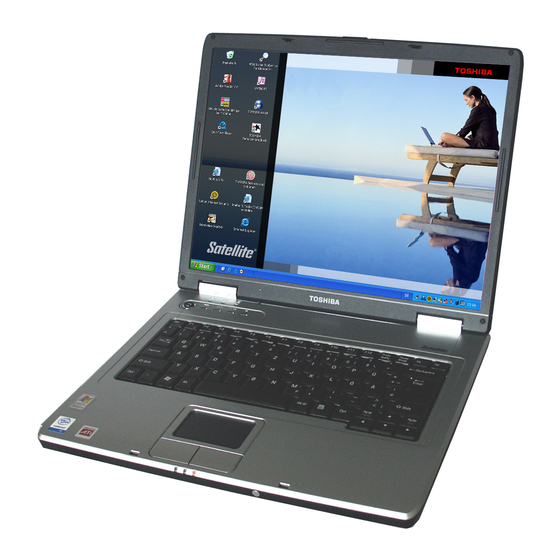
- Page 1 TOSHIBA Satellite L20 Series User's Manual...
- Page 2 TOSHIBA L20 Series Copyright © 2005 by TOSHIBA Corporation. All rights reserved. Under the copyright laws, this manual cannot be reproduced in any form without the prior written permission of TOSHIBA. No patent liability is assumed, with respect to the use of the information contained herein.
-
Page 3: Fcc Information
Only peripherals complying with the FCC class B limits may be attached to this equipment. Operation with non-compliant peripherals or peripherals not recommended by TOSHIBA is likely to result in interference to radio and TV reception. Shielded cables must be used between the external devices and the computer’s external monitor port, USB port, serial port,... -
Page 4: Fcc Conditions
Irvine, California 92618-1697 Telephone: (949) 583-3000 BSMI Notice (Taiwan Only) EU Declaration of Conformity TOSHIBA declares, that the product: TOSHIBA L20 series conforms to the following Standards: Supplementary “The product complies with the requirements of Information: the Low Voltage Directive 73/23/EEC, the EMC Directive 89/336/EEC and/or the R&TTE Directive... - Page 5 Note that Canadian Department of Communications (DOC) regulations provide, that changes or modifications not expressly approved by TOSHIBA Corporation could void your authority to operate this equipment. This Class B digital apparatus meets all requirements of the Canadian Interference-Causng Equipment Regulations.
-
Page 6: Region Selection
TOSHIBA L20 Series Japan regulations Region selection If you are using the computer in Japan, technical regulations described in the Telecommunications Business Law require that you select the Japan region mode. It is illegal to use the modem in Japan with any other selection. -
Page 7: Telephone Company Procedures
FCC. In the event repairs are ever needed on your modem, they should be performed by TOSHIBA Corporation or an authorized representative of TOSHIBA Corporation. - Page 8 TOSHIBA L20 Series Instructions for IC CS-03 certified equipment 1. The Industry Canada label identifies certified equipment. This certification means that the equipment meets certain telecommunications network protective, operational and safety requirements as prescribed in the appropriate Terminal Equipment Technical Requirements document(s). The Department does not guarantee the equipment will operate to the user’s satisfaction.
- Page 9 TOSHIBA L20 Series Notes for Users in Australia and New Zealand Modem warning notice for Australia Modems connected to the Australian telecoms network must have a valid Austel permit. This modem has been designed to specifically configure to ensure compliance with Austel standards when the country/region selection is set to Australia.
- Page 10 TOSHIBA L20 Series ■ Immediately disconnect this equipment should it become physically damaged, and arrange for its disposal or repair. ■ The correct settings for use with this modem in New Zealand are as follows: ATB0 (CCITT operation) AT&G2 (1800 Hz guard tone) AT&P1 (Decadic dialing make-break ratio = 33%/67%)
-
Page 11: Optical Disc Drive Safety Instructions
TOSHIBA L20 Series General conditions As required by PTC 100, please ensure that this office is advised of any changes to the specifications of these products which might affect compliance with the relevant PTC Specifications. The grant of this Telepermit is specific to the above products with the marketing description as stated on the Telepermit label artwork. - Page 12 TOSHIBA L20 Series Panasonic DVD Super Multi UJ-841B ■ The DVD Super Multi drive employs a laser system. To ensure proper use of this product, please read this instruction manual carefully and retain for future reference. Should the unit ever require maintenance, contact an authorized service location.
- Page 13 TOSHIBA L20 Series TEAC DVD Super Multi DV-W28EA ■ The DVD Super Multi drive employs a laser system. To ensure proper use of this product, please read this instruction manual carefully and retain for future reference. Should the unit ever require maintenance, contact an authorized service location.
- Page 14 TOSHIBA L20 Series Hitachi-LG Data Storage, Inc. DVD Super Multi GSA-4082N ■ The DVD Super Multi drive employs a laser system. To ensure proper use of this product, please read this instruction manual carefully and retain for future reference. Should the unit ever require maintenance, contact an authorized service location.
- Page 15 TOSHIBA L20 Series Pioneer DVD Super Multi DVR-K16 ■ The DVD Super Multi drive employs a laser system. To ensure proper use of this product, please read this instruction manual carefully and retain for future reference. Should the unit ever require maintenance, contact an authorized service location.
- Page 16 TOSHIBA L20 Series TOSHIBA SAMSUNG STORAGE TECHNOLOGY CD-RW/DVD-ROM TS-L462C ■ The CD-RW/DVD-ROM drive employs a laser system. To ensure proper use of this product, please read this instruction manual carefully and retain for future reference. Should the unit ever require maintenance, contact an authorized service location.
- Page 17 TOSHIBA L20 Series Panasonic CD-RW/DVD-ROM UJDA770 ■ The CD-RW/DVD-ROM drive employs a laser system. To ensure proper use of this product, please read this instruction manual carefully and retain for future reference. Should the unit ever require maintenance, contact an authorized service location.
- Page 18 TOSHIBA L20 Series Hitachi-LG Data Storage, Inc. CD-RW/DVD-ROM GCC-4244N ■ The CD-RW/DVD-ROM drive employs a laser system. To ensure proper use of this product, please read this instruction manual carefully and retain for future reference. Should the unit ever require maintenance, contact an authorized service location.
- Page 19 TOSHIBA L20 Series International precautions CAUTION: This appliance contains a laser system and is classified as a "CLASS 1 LASER PRODUCT." To use this model properly, read the instruction manual carefully and keep this manual for your future reference. In case of any trouble with this model, please contact your nearest "AUTHORIZED service station."...
- Page 20 TOSHIBA L20 Series OBS! Apparaten innehåller laserkomponent som avger laserstråining överstigande gränsen för laserklass 1. VAROITUS. Suojakoteloa si saa avata. Laite sisältää laserdiodin, joka lähetää näkymätöntä silmilie vaarallista lasersäteilyä. CAUTION: USE OF CONTROLS OR ADJUSTMENTS OR PERFORMANCE OF PROCEDURES OTHER THAN THOSE SPECIFIED IN THE OWNER’S...
-
Page 21: General Precautions
TOSHIBA L20 Series General Precautions TOSHIBA computers are designed to optimize safety, minimize strain and withstand the rigors of portability. However, certain precautions should be observed to further reduce the risk of personal injury or damage to the computer. Be certain to read the general precautions below and to note the cautions included in the text of the manual. - Page 22 For optimum performance, use your computer product only under recommended conditions Read additional restrictions under "Environmental Requirements" in appendix A, Specifications. Contact TOSHIBA Technical Service and Support for more information. xxii User’s Manual...
-
Page 23: Working Environment
EMC (Electromagnetic Compatibility) and safety standards. However, TOSHIBA cannot guarantee that this product still observes these EMC standards if options or cables not produced by TOSHIBA are connected or implemented. In this case the persons who have connected / implemented those options / cables have to provide assurance that the system (PC plus options / cables) still fulfils the required standards. -
Page 24: Wireless Lan And Your Health
Because Wireless LAN products operate within the guidelines found in radio frequency safety standards and recommendations, TOSHIBA believes Wireless LAN is safe for use by consumers. These standards and recommendations reflect the consensus of the scientific community and result from deliberations of panels and committees of scientists who continually review and interpret the extensive research literature. -
Page 25: Limitation Of Liability
General Precautions Limitation of Liability For damage occurring due to an earthquake or thunder, fire beyond our responsibility, action by third party, other accident, intentional or accidental mistakes by a user, misuse, use under abnormal conditions, we do not take any responsibility. - Page 26 General Precautions WARNING Turn OFF the Wireless Communication switch of Wireless Products in a congested place, such as a crowded commuter train. Keep this product away from a cardiac pacemaker at least 22cm. Radio waves can potentially affect cardiac pacemaker operation, thereby causing respiratory troubles.
-
Page 27: Table Of Contents
TOSHIBA L20 Series Table of Contents Preface Manual contents ........xxxiii Conventions . - Page 28 Table of Contents Fixed optical media drives ....... . .2-10 Region codes for DVD drives and media .
- Page 29 DLA for TOSHIBA ........
- Page 30 Table of Contents The Keyboard Chapter 5 Typewriter keys ......... . .5-1 F1 ...
- Page 31 TOSHIBA support ........
- Page 32 Table of Contents Specifications Appendix A Display Controller and Modes Appendix B Wireless LAN Appendix C AC Power Cord and Connectors Appendix D Glossary Index xxxii User’s Manual...
-
Page 33: Preface
This manual tells how to set up and begin using your TOSHIBA L20 Series computer. It also provides detailed information on configuring your computer, basic operations and care, using optional devices and troubleshooting. -
Page 34: Conventions
Preface Chapter 4, Operating Basics, includes instructions on using the following devices: TouchPad, optional USB floppy disk drive, Audio/Video controls, Sound System, optical media drives, modem, wireless communication and LAN. It also provides tips on care of the computer, floppy disks and CD/ DVDs. -
Page 35: Key Operation
Preface Key operation Some operations require you to simultaneously use two or more keys. We identify such operations by the key top symbols separated by a plus sign (+). For example, Ctrl + C means you must hold down Ctrl and at the same time press C. - Page 36 Preface xxxvi User’s Manual...
-
Page 37: Introduction
Some of the features described in this manual may not function properly if you use an operating system that was not preinstalled by TOSHIBA. Equipment checklist Carefully unpack your computer. Save the box and packing materials for future use. -
Page 38: Software
■ TOSHIBA PC Diagnostic Tool ■ TOSHIBA Zooming Utility Other software may preinstalled dependant on the model purchased. Documentation ■ TOSHIBA L20 Series User's Manual ■ TOSHIBA L20 Quickstart * ■ Safety Instruction Manual ■ Warranty information Backup Media and Addtional Software ■... -
Page 39: Features
Introduction Features The computer uses TOSHIBA's advanced Large Scale Integration (LSI), Complementary Metal-Oxide Semiconductor (CMOS) technology extensively to provide compact size, minimum weight, low power usage, and high reliability. This computer incorporates the following features and benefits: Processor Built-in ®... - Page 40 Introduction RTC Battery The internal RTC battery backs up the Real Time Clock and calendar. AC Adaptor The universal AC adaptor provides power to the system and recharges the batteries when they are low. It comes with a detachable power cord. Because it is universal, it can receive a range of AC voltage from 100 to 240 volts;...
- Page 41 Introduction Some models are equipped with a full-size, CD-RW/DVD-ROM CD-RW/DVD-ROM drive module that lets you run drive CD/DVDs without using an adaptor. It reads DVD-ROMs at maximum 8 speed and CD-ROMs at maximum 24 speed. It writes CD-R at up to 24 speed and CD-RW at up to 24 speed.
-
Page 42: Pointing Device
Introduction Display The computer's LCD panel supports high-resolution video graphics. The screen can be set at a wide range of viewing angles for maximum comfort and readability. Built-In 15.0" XGA TFT screen, 16 M colors, with the following resolution: XGA, 1024 horizontal × 768 vertical pixels Graphics Controller Graphics controller maximizes display performance. - Page 43 Introduction Multimedia Sound System ® A Windows Sound System compatible sound system provides speakers as well as jacks for an external microphone and headphones. Video-Out Jack The video out jack lets you transfer video data to (S-Video) external devices. Data output depends on the type of device connected to the S-Video cable.
- Page 44 Operating System ® ® Windows XP Home Edition, or Windows Professional Edition operating system and TOSHIBA Utilities and drivers preinstalled on the hard disk. Refer to the Software section at the front of this chapter. TOSHIBA Utilities A number of utilities and drivers are preinstalled to make your computer more convenient to use.
-
Page 45: Special Features
Introduction Special features The following features are either unique to TOSHIBA computers or are advanced features, which make the computer more convenient to use. Please note that the descriptions for starting some special features are based on setting the Control Panel to Category View. On Classic view the description is different. - Page 46 Introduction System Automatic This feature automatically shuts down the system Standby/Hibernation in Standby Mode or Hibernation Mode when there is no input or hardware access for a time specified. To specify the time, click start, Control Panel, Performance and Maintenance, Power Options.
-
Page 47: Utilities
Control Panel to Category View. On Classic view the description is different. TOSHIBA Assist TOSHIBA Assist is a graphical user interface that provides easy access to help and services. HW Setup This program lets you customize your hardware settings according to the way you work with your computer and the peripherals you use. - Page 48 Tool, click start, point to All Programs, point to TOSHIBA, and point to Utilities and click PC Diagnostic Tool. TOSHIBA ConfigFree ConfigFree is a suite of utilities to allow easy control of communication device and network connections. ConfigFree also allows you to find...
-
Page 49: Options
(PC4200 DDR2) can easily be installed in the computer. Battery pack An additional battery pack can be purchased from your TOSHIBA dealer. Use it as a spare or replacement. Battery pack (4300/2000 mAh) AC Adaptor If you use your computer at more than one site... - Page 50 Introduction 1-14 User’s Manual...
-
Page 51: Chapter 2 The Grand Tour
TOSHIBA L20 Series Chapter 2 The Grand Tour This chapter identifies the various components of your computer. Become familiar with each component before you operate the computer. Front with the display closed The following figure shows the computer's front with its display panel in the closed position. -
Page 52: Left Side
The Grand Tour Left side The following figure shows the computer's left side. Cooling Vents Headphone Jack External Monitor Port USB Ports Microphone Jack PC Card Slot The left side of the computer External Monitor This 15-pin port lets you connect an external Port video display. -
Page 53: Right Side
The Grand Tour Right side The following figure shows the computer's right side. ODD Indicator Security Lock Emergency Eject Eject Button Fixed Optical Media Disc Drive Hole The right side of the computer Fixed Optical Media The computer is configured with a full-size optical Disc Drive media drive module that lets you run either 12 cm (4.72") or 8 cm (3.15") disks without using an... -
Page 54: Backside
The Grand Tour Backside The following figure shows the computer's back panel (It differs depending on the model). DC IN 19V Jack USB Port Modem Jack Video-Out Jack LAN Jack The backside of the computer Universal Serial Bus A Universal Serial Bus port is on the right side. (USB 2.0) port Refer to the Left side... -
Page 55: Underside
The Grand Tour Underside The following figure shows the underside of the computer. Make sure the display is closed before turning over your computer. Battery Pack Battery Release Latch (2) Battery Release Cooling Lock (1) Vents Memory Module Cover Wireless Cover The underside of the computer Battery Release... -
Page 56: Front With The Display Open
The Grand Tour Front with the display open This section shows the front of the computer with the display open. Refer to the appropriate illustration for details. To open the display, slide the display latch on the front of the display and lift up. Position the display at a comfortable viewing angle. - Page 57 The Grand Tour Display Screen The LCD displays high-contrast text and graphics. Refer to Display Controller and Modes section in Appendix B, Display Controller and Modes. When the computer operates on the AC adaptor the display screen’s image will be somewhat brighter than when it operates on battery power.
-
Page 58: System & Keyboard Indicators
The Grand Tour System & Keyboard indicators Built-in HDD Caps Lock NumLock Wireless Activity Power Battery System & Keyboard overlay indicators Power The Power indicator glows green when the computer is on. If you select Standby from Shutdown windows, this indicator flashes orange (one second on, two seconds off) while the computer shuts down. -
Page 59: Usb Floppy Disk Drive (Optional)
The Grand Tour USB floppy disk drive (optional) An optional 3 ½" floppy disk drive accommodates 1.44-megabyte or 720- kilobyte floppy disks. It connects to the USB port. Disk-In-Use Floppy Eject Indicator Disk Slot Button USB floppy disk drive Disk-In-Use Indicator This indicator lights when the floppy disk is being accessed. -
Page 60: Fixed Optical Media Drives
The Grand Tour Fixed optical media drives One of the following optical media drives is installed in the computer: CD-RW/DVD-ROM or DVD Super Multi drives. An ATAPI interface controller is used for CD/DVD-ROM operation. When the computer is accessing a CD/DVD, an indicator on the drive glows. Region codes for DVD drives and media CD-RW/DVD-ROM and the DVD Super Multi drives and their associated media are manufactured according to the specifications of six marketing... -
Page 61: Dvds
The Grand Tour DVDs ■ DVD-R and DVD-R DL discs can be written only once. The recorded data cannot be erased or changed. ■ DVD-RW discs can be recorded more than once. ■ DVD-RAM discs can be recorded more than once. ■... -
Page 62: Dvd Super Multi Drive (Supporting Dvd±R Double Layer)
The Grand Tour DVD Super Multi drive (Supporting DVD±R Double Layer) The full-size DVD Super Multi drive module lets you record data to rewritable CD/DVDs as well as run either 12 cm (4.72") or 8 cm (3.15") CD/ DVDs without using an adaptor. The read speed is slower at the center of a disc and faster at the outer edge. - Page 63 Use only the AC adaptor that came with the computer or an equivalent optional adaptor. Use of the wrong adaptor could damage your computer. TOSHIBA assumes no liability for any damage in such case. ■ Use only the AC Adaptor supplied with your computer or an equivalent adapter that is compatible.
- Page 64 The Grand Tour 2-14 User’s Manual...
-
Page 65: Getting Started
TOSHIBA L20 Series Chapter 3 Getting Started This chapter provides basic information to get you started using your computer. It covers the following topics: ■ Setting up your work space — for your health and safety Be sure also to read the Safety Instruction Manual. This guide, which is included with the computer, explains product liability. -
Page 66: Setting Up Your Work Space
Getting Started Setting up your work space Establishing a comfortable work site is important for you and your computer. A poor work environment or stressful work habits can result in discomfort or serious injury from repetitive strain to your hands, wrists or other joints. -
Page 67: Placement Of The Computer
Getting Started Placement of the computer Position the computer and peripheral devices to provide comfort and safety. ■ Set the computer on a flat surface at a comfortable height and distance. ■ The display should be no higher than eye level to avoid eyestrain. ■... -
Page 68: Lighting
Getting Started Lighting Proper lighting can improve legibility of the display and reduce eyestrain. ■ Position the computer so that sunlight or bright indoor lighting does not reflect off the screen. Use tinted Windows, shades or other screen to eliminate sun glare. ■... -
Page 69: Installing The Battery Pack
Dispose of the battery as required by local ordinances or regulations. Use only batteries recommended by TOSHIBA as replacements. ■ Do not touch the latch while holding the computer. Or you may get injured by the dropped battery by unintentional release of the latch. -
Page 70: Connecting The Ac Adaptor
Use only the AC adaptor supplied with your computer or an equivalent adaptor that is compatible. Use of any incompatible adaptor could damage your computer. TOSHIBA assumes no liability for any damage caused by use of an incompatible adaptor. ■... -
Page 71: Opening The Display
Getting Started 2. Connect the AC adaptor's DC output plug to the DC IN 19V jack on the back of the computer. Connecting the adaptor to the computer 3. Plug the power cord into a live wall outlet. Opening the display The display panel can be rotated in a wide range of angles for optimal viewing. -
Page 72: Turning On The Power
Getting Started Turning on the power This section describes how to turn on the power. After you turn on the power for the first time, do not turn it off until you have set up the operating system. Refer to the section Windows®... -
Page 73: Turning Off The Power
Getting Started Turning off the power The power can be turned off in one of the following modes: Shut down (Boot), Hibernation or Standby Mode. Shut Down mode (Boot mode) When you turn off the power in Shut Down mode no data is saved and the computer will boot to the operating system’s main screen. -
Page 74: Starting Hibernation Mode
Getting Started Benefits of Hibernation Mode The Hibernation Mode feature provides the following benefits: ■ Saves data to the hard disk when the computer automatically shuts down because of a low battery. For the computer to shut down in Hibernation Mode, the hibernation feature must be enabled in the Hibernate tab in Power Options. -
Page 75: Standby Mode
Getting Started Data save in Hibernation Mode When you turn off the power in Hibernation Mode, the computer takes a moment to save current memory data to the hard disk. During this time, the Disk indicator will light. After you turn off the computer and memory is saved to the hard disk, turn off the power to any peripheral devices. -
Page 76: Restarting The Computer
Getting Started Entering Standby Mode You can enter Standby Mode in one of three ways: 1. Click Start, click Turn Off Computer and click Stand by. 2. Close the display panel. 3. Press the power button. When you turn the power back on, you can continue where you left when you shut down the computer. -
Page 77: Restoring The Preinstalled Software
2. Wait 10 to15 seconds, then turn on the computer again. 3. When In Touch with Tomorrow TOSHIBA appears, press the F12 key. 4. Use the up or down cursor key to select the CD-ROM/DVD-ROM icon in the display menu. - Page 78 Getting Started 3-14 User’s Manual...
-
Page 79: Operating Basics
TOSHIBA L20 Series Chapter 4 Operating Basics This chapter gives information on basic operations including using the TouchPad, the optional USB floppy disk drive, optical media drives, audio/ video controls, sound system, modem, the wireless LAN and LAN. It also provides tips on caring for your computer and on heat dispersal. -
Page 80: Using The Usb Floppy Disk Drive
Operating Basics For some functions, you can tap the TouchPad instead of pressing a control button. Click: Tap the TouchPad once Double-click: Tap the TouchPad twice Drag and drop: 1. Hold down the left control button and move the cursor to drag the item you want to move. -
Page 81: Disconnecting 3 ½" Floppy Disk Drive
Operating Basics Disconnecting 3 ½" floppy disk drive When you have finished using the floppy disk drive, follow the procedures below to disconnect it: 1. Wait for the indicator light to go out to make sure all floppy disk activity has stopped. -
Page 82: Loading Discs
Operating Basics Loading discs To load a disc, follow the steps below and refer to the figures. 1. a. When the power is on, press the DVD-ROM eject button to open the drawer slightly. Eject Button Pressing the DVD-ROM eject button b. - Page 83 Operating Basics 2. Grasp the drawer gently and pull until it is fully opened. Pulling the drawer open 3. Place the disc, label side up, in the drawer. Inserting a disc When the drawer is fully opened, the edge of the computer will extend slightly over the disc tray.
- Page 84 Operating Basics 4. Press gently at the center of the disc until you feel it click into place. The disc should lie below the top of the spindle, flush with the spindle base. 5. Push the center of the drawer to close it. Press gently until it locks into place.
-
Page 85: Removing Discs
Operating Basics Removing discs To remove the disc, follow the steps below and refer to the figure. Do not press the eject button while the computer is accessing the disc drive. Wait for the optical media drive indicator to go out before you open the drawer. -
Page 86: Audio/Video Controls
Operating Basics Audio/Video controls This section describes how to use the audio/video control buttons. Next and Previous buttons Press on the button to select the desired function. Next Press the button to advance to the next track, chapter or data. Previous Press the button to advance to the previous track,... -
Page 87: Writing Cds With On Cd-Rw/Dvd-Rom Drive
Operating Basics Writing CDs with on CD-RW/DVD-ROM drive Depending on the type of drive installed, you may be able to write CDs. The CD-RW/DVD-ROM drive lets you read DVD-ROMs and CDs as well as write CD-R/RW. Observe the precautions in this section to ensure the best performance for writing CDs. -
Page 88: When Writing Or Rewriting
Operating Basics TOSHIBA has confirmed the operation of CD-R and CD-RW media of the manufacturers above. Operation of other media cannot be guaranteed. ■ CD-RW can generally be rewritten about 1,000 times. However, the actual number of rewrites is affected by the quality of the media and the way it is used. -
Page 89: Disclaimer (Cd-Rw/Dvd-Rom Drive)
Operating Basics Disclaimer (CD-RW/DVD-ROM drive) TOSHIBA does not bear responsibility for the following: ■ Damage to any CD-R/RW disc that may be caused by writing or rewriting with this product. ■ Any change or loss of the recorded contents of CD-R/RW disc that may... -
Page 90: Before Writing Or Rewriting
Based on TOSHIBA's limited compatibility testing, we suggest the following manufacturers of CD-R/RW and DVD-R/+R/-RW/+RW/-RAM disc. However, in no event does TOSHIBA guarantee the operation, quality or performance of any disc. Disc quality can affect write or rewrite success rates. - Page 91 Operating Basics This drive cannot use discs that allow writing of 8 speeds or more (DVD-R, DVD+R ), or 4 speeds or more (DVD-RW, DVD+RW) ■ If the disc is poor in quality, dirty or damaged, writing or rewriting errors may occur.
-
Page 92: When Writing Or Rewriting
Operating Basics ■ Write from the computer's hard disk drive to the CD/DVD. Do not try to write from shared devices such as a LAN server or any other network device. ■ Writing with software other than RecordNow! is not recommended. When writing or rewriting Please observe/consider the following when you write or rewrite to a CD-R/ -RW, DVD-R/-RW/-RAM or DVD+R/+RW disc. -
Page 93: Recordnow! Basic For Toshiba
Operating Basics RecordNow! Basic for TOSHIBA Note the following limitations when you use RecordNow!: ■ DVD-Video cannot be created using RecordNow!. ■ DVD-Audio cannot be created using RecordNow!. ■ You cannot use RecordNow!'s "Audio CD for Car or Home CD Player"... -
Page 94: Dla For Toshiba
3. Mark the Verify data written to the disc after burning check box in the Data Options. 4. Click OK. DLA for TOSHIBA Note the following limitations when you use DLA: ■ This software supports only rewritable discs (DVD+RW, DVD-RW, and CD-RW). -
Page 95: Intervideo Windvd Creator Platinum
Operating Basics InterVideo WinDVD Creator Platinum Please refer to the on-line Help for additional InterVideo WinDVD Creator information. When writing the Setup files for the program into a disc formatted by DLA and starting Setup from this disc, an error may occur. In this case, plase copy them to your hard disk and then run Setup. - Page 96 Operating Basics 2. Before recording the video to DVD ■ When you record to DVD disc, please use only discs recommended by the Drive manufacturer. ■ Do not set the working drive to a slow device like a USB 1.1 hard disk drive or it will fail to write DVD.
-
Page 97: Media Care
Operating Basics Media care This section provides tips on protecting data stored on your CD/DVDs and floppy disks. Handle your media with care. The following simple precautions will increase the lifetime of your media and protect the data stored on them: CD/DVDs 1. -
Page 98: Sound System
Operating Basics Sound System This section describes audio controls including sound levels and power management. Volume control ® The Volume Control utility lets you control the audio volume in Windows for both playback and recording. ■ To launch Volume Control for playback, click start, point to All Programs, point to Accessories, point to Entertainment and click Volume Control. -
Page 99: Region Selection
To select a region, follow the steps below. 1. Click start, point to All Programs, TOSHIBA, Networking, and click Modem Region Select. Do not use the Country/Region Select function in the Modem setup utility in the Control Panel if the function is available. -
Page 100: Modem Selection
Operating Basics Open dialog box, if the modem and Telephony Current Location region code do not match. A warning dialog box is displayed if current settings for region code and telephony location are incorrect. Modem Selection If the computer cannot recognize the internal modem, a dialog box is displayed. -
Page 101: Disconnecting
TOSHIBA strongly recommend the customer to enable the encryption function. ■ TOSHIBA is not liable for the eavesdropping of data due to the use of Wireless LAN and the damage thereof. Wireless communication switch You can enable or disable the Wireless LAN function, with the on/off switch. -
Page 102: Wireless Communication Indicator
Operating Basics Wireless communication indicator The wireless communication indicator indicates the status of the wireless communication functions. Indicator status Indication Indicator off Wireless communication switch is set to off. Automatic power down because of overheating. Power malfunction Indicator glows Wireless communication switch is on. Wireless LAN is turned on by an application. -
Page 103: Connecting Lan Cable
Operating Basics Connecting LAN cable To connect the LAN cable, follow the steps below. 1. Turn off the power to the computer and to all external devices connected to the computer. 2. Plug one end of the cable into the LAN jack. Press gently until you hear the latch click into place. -
Page 104: Moving The Computer
Operating Basics Moving the computer The computer is designed for rugged durability. However, a few simple precautions taken when moving the computer will help ensure trouble-free operation. ■ Make sure all disk activity has ended before moving the computer. Check the Disk indicator on the computer. ■... -
Page 105: The Keyboard
TOSHIBA L20 Series Chapter 5 The Keyboard The computer's keyboard layouts are compatible with a 101/102-key enhanced keyboard. By pressing some keys in combination, all the 101/ 102-key keyboard functions can be executed on the computer. The number of keys on your keyboard depends on which country/region’s keyboard layout your computer is configured with. -
Page 106: F1 ... F12 Function Keys
The Keyboard F1 ... F12 function keys The function keys (not to be confused with Fn) are the 12 keys at the top of your keyboard. These keys function differently from other keys. F1 through F12 are called function keys because they execute programmed functions when pressed. -
Page 107: Hot Keys
The Keyboard Hot keys Hot keys let you enable or disable certain features of the computers. ® Sound mute: Pressing Fn + Esc in a Windows environment turns sound on or off. When you press these hot keys, the current setting will change and be displayed as an icon. - Page 108 The Keyboard LCD Display Brightness: Pressing Fn + F6 decreases the display brightness in decrements. When you press these hot keys, the current setting will be displayed for two seconds by an icon. LCD Display Brightness: Pressing Fn + F7 increases the display brightness in increments.
-
Page 109: Fn Sticky Key
Fn Sticky key You can use the TOSHIBA Accessibility Utility to make the Fn key sticky, that is, you can press it once, release it, and then press an " F number" key. To start the TOSHIBA Accessibility Utility, click start, point to All Programs, point to TOSHIBA, point to Utilities and click Accessibility. -
Page 110: Windows® Special Keys
The Keyboard ® Windows special keys ® The keyboard provides two keys that have special functions in Windows ® Windows logo key activates the start menu and the other, the application key, has the same function as the secondary mouse button. ®... -
Page 111: Temporarily Using Normal Keyboard (Overlay On)
The Keyboard Temporarily using normal keyboard (overlay on) While using the overlay, you can temporarily access the normal keyboard without turning off the overlay: 1. Hold Fn and press any other key. All keys will operate as if the overlay were off. - Page 112 The Keyboard User’s Manual...
-
Page 113: Power And Power-Up Modes
TOSHIBA L20 Series Chapter 6 Power and Power-Up Modes The computer's power resources include the AC adaptor and internal batteries. This chapter gives details on making the most effective use of these resources including charging and changing batteries, tips for saving battery power, and power up modes. -
Page 114: Power Indicator
Power and Power-Up Modes Check the Battery indicator to determine the status of the battery pack. The following indicator lights indicate the battery status: Flashing orange The battery charge is low. The AC adaptor must be connected to recharge the battery. Orange Indicates the AC adaptor is connected and charging the battery. -
Page 115: Battery Types
Dispose of the battery as required by local ordinances or regulations. Use only batteries recommended by TOSHIBA as replacements. ■ Do not remove the battery pack while the computer is in Standby Mode. -
Page 116: Real Time Clock Battery
The computer's RTC battery is a lithium ion battery and should be replaced only by your dealer or by a TOSHIBA service representative. The battery can explode if not properly replaced, used, handled or disposed of. -
Page 117: Care And Use Of The Battery Pack
Power and Power-Up Modes Care and use of the battery pack The battery pack is a vital component of portable computing. Taking proper care of it will help ensure longer operating time on battery power as well as a longer life for your battery pack. Follow the instructions in this section carefully to ensure safe operation and maximum performance. - Page 118 Never use the computer again until it has been checked by a TOSHIBA service provider. It might generate smoke or fire, or the battery pack might rupture. 3. Make sure the battery is securely installed in the computer before attempting to charge the battery pack.
-
Page 119: Charging The Batteries
Power and Power-Up Modes 6. Be sure to monitor the remaining battery power. If the battery pack and real time clock battery discharge completely, Standby and Suspend will not function and data in memory will be lost. Also, the computer might register an incorrect time and date. -
Page 120: Battery Charging Notice
Power and Power-Up Modes Time The following table shows the approximate time required to fully charge a discharged battery. Charging time (hours) Battery type Power on Power off Battery pack (4300 mAh) About 6 or longer About 3 Battery pack (2000 mAh) About 6 or longer About 3 RTC battery About 24... -
Page 121: Monitoring Battery Capacity
Power and Power-Up Modes Monitoring battery capacity Remaining battery power can be monitored in the taskbar and in the ® Windows Power Options control panel utility. ■ Wait at least 16 seconds after turning on the computer before trying to monitor the remaining operating time. -
Page 122: Retaining Data With Power Off
Power and Power-Up Modes Retaining data with power off When you turn off your computer with fully charged batteries, the batteries retain data for the following approximate time periods. Battery pack (4300 mAh) About 3 days (Standby mode) About 30 days (Boot mode) Battery pack (2000 mAh) About 1 days (Standby mode) About 30 days (Boot mode) -
Page 123: Replacing The Battery Pack
Power and Power-Up Modes Replacing the battery pack When the battery pack reaches the end of its operating life you will need to install a new one. The life of the battery pack is generally about 500 recharges. If the Battery indicator flashes orange shortly after fully recharging the battery, the battery pack needs to be replaced. -
Page 124: Installing The Battery Pack
Dispose of the battery as required by local ordinances or regulations. Use only batteries recommended by TOSHIBA as replacements. ■ Do not touch the latch while holding the computer. Or you may get injured by the dropped battery by unintentional release of the latch. -
Page 125: Power-Up Modes
Power and Power-Up Modes Power-up modes The computer has the following power-up modes: ■ Boot Mode: Computer shuts down without saving data. Always save your work before you turn the computer off in boot mode. ■ Hibernation Mode: Data in memory is saved to the hard disk. ■... - Page 126 Power and Power-Up Modes 6-14 User’s Manual...
-
Page 127: Chapter 7 Optional Devices
TOSHIBA L20 Series Chapter 7 Optional Devices Optional devices can expand the computer's capabilities and its versatility. This chapter describes connection or installation of the following devices, which are available from your TOSHIBA dealer: Cards/memory ■ PC card ■ Memory expansion Power devices ■... -
Page 128: Pc Card
The computer is equipped with a PC Card expansion slot that can accommodate one 5 mm Type II card. Any PC Card that meets industry standards (manufactured by TOSHIBA or other vendor) can be installed. The slot supports 16-bit PC Cards, including PC Card 16’s multifunction card and CardBus PC Cards. -
Page 129: Removing A Pc Card
Optional Devices Removing a PC Card ■ Before removing a PC Card, make sure that any applications or system services do not use the card. ■ Be sure to disable the PC Card prior to removing it. Otherwise, the system may be fatally damaged. To remove the PC Card, follow the steps below. -
Page 130: Memory Expansion
RAM. This section describes how to install and remove a memory module. ■ Use only memory modules approved by TOSHIBA. ■ Do not try to install or remove a memory module under the following conditions. You can damage the computer and the module. Also, data will be lost. -
Page 131: Installing A Memory Module
Optional Devices Installing a memory module Follow the steps below to install a memory module. 1. Set the computer to boot mode and turn off the power. 2. Remove all cables connected to the computer. 3. Turn the computer upside down and remove the battery pack (refer to Chapter 6, Power and Power-Up Modes). -
Page 132: Removing A Memory Module
Optional Devices 7. Push the module down so it lies flat. Latches on either side will click into place to secure the module. Slot A Slot B Installing the memory module 8. Seat the cover and secure it with the screws. 9. -
Page 133: Additional Battery Pack
Optional Devices 5. Grasp the module by the sides and pull it out. ■ If you use the computer for a long time, the memory modules will become hot. In this case, let the memory modules cool to room temperature before you replace them. Or you will get burnt if you touch any of them. -
Page 134: Usb Floppy Disk Drive
Optional Devices USB floppy disk drive The 3 ½" external floppy disk drive module can be connected to the USB port. For details on connecting the 3 ½" external floppy disk drive module, refer to Chapter 4, Operating Basics. External monitor An external analog monitor can be connected to the external monitor port on the computer. - Page 135 Optional Devices A TV output feature is provided with some models. You can connect a television set to the Video out jack on the computer. Follow the steps below. If a television is connected to the computer, set the TV type in Display Properties.
-
Page 136: Changing The Resolution
Optional Devices Changing the resolution If you want to change the resolution, follow the steps below. 1. Click start and click Control Panel, then Appearance and Themes. 2. Double-click the Display icon to open the Display Properties window. 3. Select the Settings tab and click Advanced. 4. -
Page 137: Troubleshooting
TOSHIBA L20 Series Chapter 8 Troubleshooting TOSHIBA designed the computer for durability. However, should problems occur, following the procedures in this chapter can help to determine the cause. All readers should become familiar with this chapter. Knowing what might go wrong can help prevent problems from occurring. -
Page 138: Preliminary Checklist
Troubleshooting Preliminary checklist Consider the simplest solution first. The items in this checklist are easy to fix and yet can cause what appears to be a serious problem. ■ Make sure you turn on all peripheral devices before you turn on the computer. -
Page 139: Hardware And System Checklist
Troubleshooting Software The problems may be caused by your software or disk. If you cannot load a software package, the media may be damaged or the program might be corrupted. Try loading another copy of the software. If an error message appears while you are using a software package, check the software documentation. -
Page 140: Self Test
This message remains on the screen for a few seconds. If the self test is successful, the computer tries to load the operating system, depending on how the Boot Priority is set in the TOSHIBA HW Setup program. If any of the following conditions are present, the self test failed: ■... -
Page 141: Ac Power
Troubleshooting AC power If you have trouble turning on the computer with the AC adaptor connected, check the Battery Indicator indicator. Refer to Chapter 6, Power and Power-Up Modes for more information. Problem Procedure AC adaptor doesn’t Check the connections. Make sure the cord is power the computer firmly connected to the computer and a power outlet. -
Page 142: Real Time Clock
Troubleshooting Problem Procedure Unplug the AC adaptor and remove the battery to make sure the terminals are clean. If necessary wipe them with a soft dry cloth dipped in alcohol. Connect the AC adaptor and replace the battery. Make sure it is securely seated. Check the Battery indicator. -
Page 143: Keyboard
Troubleshooting Keyboard Keyboard problems can be caused by your setup configuration. For more information refer to Chapter 5, Keyboard. Problem Procedure Some letter keys Check that the numeric keypad overlay is not produce numbers selected. Press Fn + F11 and try typing again. Output to screen is Make sure the software you are using is not garbled... -
Page 144: Cd-Rw/Dvd-Rom Drive
Troubleshooting CD-RW/DVD-ROM drive For more information, refer to Chapter 4, Operating Basics. Problem Procedure You cannot access a Make sure the drive’s drawer is securely closed. CD/DVD in the drive Press gently until it clicks into place. Open the drawer and make sure the CD/DVD is properly seated. -
Page 145: Dvd Super Multi Drive (Supporting Dvd±R Double Layer)
Procedure Cannot write correctly If you have trouble writing, make sure you are observing the following precautions: ■ Use only media recommended by TOSHIBA. ■ Do not use the mouse or keyboard during writing. ■ Use only the software supplied with the computer for recording. -
Page 146: Floppy Disk Drive
Troubleshooting Problem Procedure Some CD/DVDs run The software or hardware configuration may be correctly, but others do causing a problem. Make sure the hardware configuration matches your software's needs.Check the CD/DVD's documentation. Check the type of CD/DVD you are using. The drive supports: DVD-ROM: DVD-ROM, DVD-Videol,... -
Page 147: Pc Card
Troubleshooting PC Card Refer also to Chapter 7, Optional Devices. Problem Procedure PC Card error occurs Reseat the PC Card to make sure it is firmly connected. Make sure the connection between the external device and the card is firm. Check the card’s documentation. -
Page 148: Usb Mouse
Troubleshooting Problem Procedure The response of the Adjust the touch sensitivity. TouchPad is too 1. Open the Control Panel. sensitive 2. Click the Printers and Other Hardware icon. 3. Click the Mouse icon. 4. Click the Device Setting tab. 5. Click the Setting button. 6. -
Page 149: Usb
Troubleshooting Problem Procedure Try changing the speed setting in the mouse The mouse pointer control utility. moves too fast or too slow 1. Open the Control Panel, select the Printers and Other Hardware icon, and press Enter. 2. Select the Mouse icon and press Enter. 3. -
Page 150: Sound System
Troubleshooting Sound system Refer also to documentation for your audio devices. Problem Procedure No sound is heard Check the software volume settings. Make sure the headphone connection is secure. If problems persist, contact your dealer. Monitor Refer also to Chapter 7, Optional Devices, and to your monitor’s documentation. -
Page 151: Lan
Troubleshooting Problem Procedure After making a call you Make sure the tone or pulse selection in your can’t hear a ring communications application is set correctly. You can also use the ATD command. Communication is cut The computer will automatically cut off off unexpectedly communication when connection with the carrier is not successful for a set time interval. -
Page 152: Printer
They are your best sources for current information and support. Where to write If you are still unable to solve the problem and suspect that it is hardware related, write to TOSHIBA at the nearest location listed on the below. 8-16 User’s Manual... - Page 153 Troubleshooting Outside of Europe In Europe Australia Germany & Austria TOSHIBA Australia Pty. Ltd. TOSHIBA Europe (I.E.) GmbH Information Systems Division Geschäftsbereich, 84-92 Talavera Road Deutschland-Österreich North Ryde N.S.W. 2113 Sydney Hammfelddamm8, D-41460 Neuss, Germany Canada France TOSHIBA of Canada Ltd.
- Page 154 Troubleshooting 8-18 User’s Manual...
-
Page 155: Specifications
TOSHIBA L20 Series Appendix A Specifications This appendix summarizes the computer's technical specifications. Physical Dimensions Weight Starting at 2.57kg/5.67lbs * * Weight may vary depending on product configuration, vendor components, manufacturing variability and options selected. Size 332 (w) x 270 (d) x 28.5/36.6 (h) millimeters (not... -
Page 156: Power Requirements
Specifications Power Requirements AC adaptor 100-240 volts AC 50 or 60 hertz (cycles per second) Computer 19 VDC 3.42 ampers Built-in Modem Network control unit (NCU) Type of NCU Type of line Telephone line (analog only) Type of dialing Pulse Tone Control command AT commands... - Page 157 Specifications Communication Data transmission and reception Speed 300/1200/2400/4800/7200/9600/12000/14400/ 16800/19200/21600/24000/26400/28800/31200/ 33600 bps Data reception only with V.90 28000/29333/30666/32000/33333/34666/36000/ 37333/38666/40000/41333/42666/44000/45333/ 46666/48000/49333/50666/52000/53333/54666/ 56000 bps 2400/4800/7200/9600/12000/14400 bps Transmitting level -10 dBm Receiving level -10 to -40 dBm Input/output 600 ohms ±30% impedance Error correcting MNP class 4 and ITU-T V.42 Data compression MNP class 5 and ITU-T V.42bis...
- Page 158 Specifications User’s Manual...
-
Page 159: Display Controller And Modes
TOSHIBA L20 Series Appendix B Display Controller and Modes Display controller The display controller interprets software commands into hardware commands that turn particular picture elements (pels) on or off. The controller is an advanced Video Graphics Array (VGA) that provides Extended Graphics Array (XGA) support for the internal LCD and external monitors. -
Page 160: Video Modes
Display Controller and Modes Video modes The computer supports video modes defined in the tables below. If your application offers a selection of mode numbers that do not match the numbers on the table, select a mode based on mode type, resolution, character matrix, number of colors and refresh rates. - Page 161 Display Controller and Modes Table 1: Video modes (VGA) (continued) Video Type Resolution Character Scanning mode matrix colors colors frequency (pels) Vertical (Hz) 320 x 200 8 x 8 16 of 256K 16 of 256K Grph Pels 640 x 200 8 x 8 16 of 256K 16 of 256K...
- Page 162 Display Controller and Modes Table 2: Video modes Resolution LCD colors CRT colors Vertical frequency (Hz) 800 x 600 256K/256K 256K/256K 1024 x 768 256K/256K 256K/256K 1280 x 1024 256K/256K 256K/256K (Virtual) 1600 x 1200 256K/256K 256K/256K (Virtual) 1920 x 1440 256K/256K 256K/256K (ATI: Virtual / Intel: Not Support)
- Page 163 Display Controller and Modes Table 2: Video modes (continued) Resolution LCD colors CRT colors Vertical frequency (Hz) 800 x 600 64K/64K 64K/64K 1024 x 768 64K/64K 64K/64K 1280 x 1024 64K/64K 64K/64K (Virtual) 1600 x 1200 64K/64K 64K/64K (Virtual) 1920 x 1440 64K/64K 64K/64K (ATI: Virtual / Intel: Not Support)
- Page 164 Display Controller and Modes Table 2: Video modes (continued) Resolution LCD colors CRT colors Vertical frequency (Hz) 800 x 600 16M/16M 16M/16M 1024 x 768 16M/16M 16M/16M 1280 x 1024 16M/16M 16M/16M (Virtual) 1600 x 1200 16M/16M 16M/16M (Virtual) 1920 x 1440 16M/16M 16M/16M (ATI: Virtual / Intel: Not Support)
-
Page 165: Display Settings
Display Controller and Modes Display Settings 1. You cannot move from the Settings tab of Display Properties to the multi-monitor when you are using the display of the computer and an external CRT display at the same time. ■ The Settings tab is displayed in the following steps; ■... - Page 166 Display Controller and Modes ■ The way to move to multi-monitor (ATI RADEON XPRESS 200M) ■ Switch to Display Properties, like shown in previous page. ■ Click Advanced in Display Properties. ■ Select Displays tab in (Multiple Monitors) and ATI RADEON XPRESS 200M Series Properties.
- Page 167 Display Controller and Modes 5. When the LCD (internal liquid crystal display) display mode is selected, the Virtual (Virtual Screen) display mode can be set. However, afterwards, it may not possible to change the screen resolution to more than 1280 x 1024 pixels in Highest (32bit) mode (for example, when you attempt to set the resolution to 1600 x 1200 using the Screen resolution slide bar and then select Highest (32bit) mode from the Color quality drop-down menu).
- Page 168 Display Controller and Modes B-10 User’s Manual...
-
Page 169: Card Specifications
TOSHIBA L20 Series Appendix C Wireless LAN Card Specifications Form Factor Mini PCI TypeIII ■ IEEE 802.11 Standard for Wireless LANs Compatibility ■ Wi-Fi (Wireless Fidelity) certified by the Wi-Fi Alliance. The "Wi-Fi CERTIFIED" logo is a certification mark of the Wi-Fi Alliance. -
Page 170: Radio Characteristics
Wireless LAN Radio Characteristics Radio Characteristics of Wireless LAN Cards may vary according to: ■ Country/region where the product was purchased ■ Type of product Wireless communication is often subject to local radio regulations. Although Wireless LAN wireless networking products have been designed for operation in the license-free 2.4GHz band, local radio regulations may impose a number of limitations to the use of wireless communication equipment. - Page 171 Subject to the radio regulations that apply in the countries/regions, your Wireless LAN card may support a different set of 2.4 GHz channels. Consult your Authorized Wireless LAN or TOSHIBA Sales office for information about the radio regulations that apply in the countries/regions.
- Page 172 Wireless LAN When installing Wireless LAN cards, the channel configuration is managed as follows: ■ For wireless clients that operate in a Wireless LAN Infrastructure, the Wireless LAN card will automatically start operation at the channel identified by the Wireless LAN Access Point. When roaming between different access points the station can dynamically switch to another channel if required.
-
Page 173: Ac Power Cord And Connectors
TOSHIBA L20 Series Appendix D AC Power Cord and Connectors The power cord’s AC input plug must be compatible with the various international AC power outlets and the cord must meet the standards for the country/region in which it is used. All cords must meet the following... - Page 174 AC Power Cord and Connectors Europe: Austria: Italy: Belgium: CEBEC The Netherlands: KEMA Denmark: DEMKO Norway: NEMKO Finland: SETI Sweden: SEMKO France: Switzerland: Germany: United Kingdom: In Europe, power cords must be VDE type, H05VVH2-F and two conductor. For the United States and Canada, plug configuration must be a 2-15P (250 V) or 1-15P (125 V) as designated in the U.S.
- Page 175 TOSHIBA L20 Series Glossary The terms in this glossary cover topics related to this manual. Alternate naming is included for reference. Abbreviations AC: alternating current AGP: accelerated graphics port ANSI: American National Standards Institute APM: advanced power manager ASCII: American Standard Code for Information Interchange...
- Page 176 Glossary LED: light emitting diode LSI: large scale integration ® MS-DOS: Microsoft Disk Operating System OCR: optical character recognition (reader) PCB: printed circuit board PCI: peripheral component interconnect RAM: random access memory RGB: red, green, and blue ROM: read only memory RTC: real time clock SCSI: small computer system interface SIO: serial input/output...
- Page 177 Glossary application: A group of programs that together are used for a specific task such as accounting, financial planning, spreadsheets, word processing and games. ASCII: American Standard Code for Information Interchange. ASCII code is a set of 256 binary codes that represent the most commonly used letters, numbers, and symbols.
- Page 178 Glossary cache memory: High speed memory which stores data that increases processor speed and data transfer rate. When the CPU reads data from main memory, it stores a copy of this data in cache memory. The next time the CPU needs that same data, it looks for it in the cache memory rather than the main memory, which saves time.
- Page 179 Glossary computer program: A set of instructions written for a computer that enable it to achieve a desired result. computer system: A combination of hardware, software, firmware, and peripheral components assembled to process data into useful information. configuration: The specific components in your system (such as the terminal, printer, and disk drives) and the settings that define how your system works.
- Page 180 Glossary disk storage: Storing data on magnetic disk. Data is arranged on concentric tracks much like a phonograph record. display: A CRT, LCD, or other image producing device used to view computer output. documentation: The set of manuals and/or other instructions written for the users of a computer system or application.
- Page 181 Fn, can be used to set system parameters, such as speaker volume. HW Setup: A TOSHIBA utility that lets you set the parameters for various hardware components. icon: A small graphic image displayed on the screen or in the indicator ®...
- Page 182 Glossary instruction: Statements or commands that specify how to perform a particular task. interface: 1) Hardware and/or software components of a system used specifically to connect one system or device to another. 2) To physically connect one system or device to another to exchange information.
- Page 183 Glossary main board: See motherboard. megabyte (MB): A unit of data storage equal to 1024 kilobytes. See also kilobyte. megahertz: A unit of wave frequency that equals 1 million cycles per second. See also hertz. menu: A software interface that displays a list of options on the screen. Also called a screen.
- Page 184 Glossary operating system: A group of programs that controls the basic operation of a computer. Operating system functions include interpreting programs, creating data files, and controlling the transmission and receipt (input/output) of data to and from memory and peripheral devices. output: The results of a computer operation.
- Page 185 A Class A device is sufficient for office use. Class B provides a more stringent classification for home equipment use. TOSHIBA portable computers comply with Class B computing device regulations. Random Access Memory (RAM): High speed memory within the computer circuitry that can be read or written to.
- Page 186 TFT display: A liquid crystal display (LCD) made from an array of liquid crystal cells using active-matrix technology with thin film transistor (TFT) to drive each cell. TouchPad: A pointing device integrated into the TOSHIBA computer palm rest. TTL: Transistor-transistor logic. A logic circuit design that uses switching transistors for gates and storage.
- Page 187 TOSHIBA L20 Series Index AC adaptor, 1-4 Display, 1-6 additional, 1-13 automatic power off, 1-9 connecting, 3-6 brightness decreases, 5-4 ASCII characters, 5-7 brightness increases, 5-4 controller, 1-6 opening, 3-7 Battery Display controller, B-1 charging, 6-7 Documentation list, 1-2 extending battery life, 6-10...
- Page 188 Index Fn + Esc (sound mute), 5-3 Fn + F1 (instant security), 5-3 Media care, 4-19 Fn + F2 (power save mode), 5-3 CD/DVDs, 4-19 Fn + F3 (standby), 5-3 floppy disks, 4-19 Fn + F4 (hibernation), 5-3 Memory, 1-3 Fn + F5 (display selection), 5-3 expansion, 1-13, 7-4 Fn + F6 (Display Brightness de-...
- Page 189 TOSHIBA ConfigFree, 1-12 LCD panel, 8-7 TOSHIBA PC DiagnosticTool, Memory expansion, 8-13 1-12 Modem, 8-14 TOSHIBA Utilities, 1-8 Monitor, 8-14 TOSHIBA Zooming Utility, 1-11 overheating power down, Touch Pad, 1-6 location, 2-6 PC card, 8-11 using, 4-1 Pointing device, 8-11 TV, 7-9...
- Page 190 Index Index-4 User’s Manual...