
Related Manuals for Pioneer A-307R


Summary of Contents for Pioneer A-307R
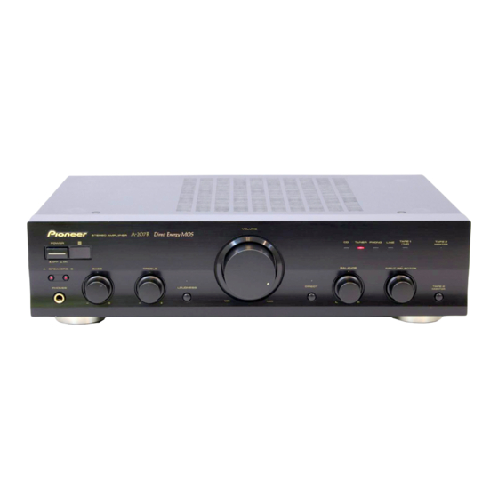
- Page 1 STEREO AMPLIFIER AMPLIFICADOR ESTEREOFONICO A-307R Operating Instructions Manual de instrucciones...
- Page 2 Operating Environment H045 En Operating environment temperature and humidity: +5°C – +35°C (+41°F – +95°F); less than 85%RH (cooling vents not blocked) Do not install in the following locations ÷ Location exposed to direct sunlight or strong artificial light ÷ Location exposed to high humidity, or poorly ventilated location LINE VOLTAGE SELECTOR SWITCH H038 En...
-
Page 3: Table Of Contents
Thank you for buying this PIONEER product. Please read through these operating instructions so you will know how to operate your model properly. After you have finished reading the instructions, put them away in a safe place for future reference. -
Page 4: Connections
CONNECTIONS Before making or changing the connections, switch off the power and disconnect the power cord from the AC outlet. H029BEn Adaptor component CD player Cassette deck/MD recorder Cassette deck Speaker system B (graphic equalizer, etc.) MINIDISC Right (R) P L A Y R E C P L A Y R E C... -
Page 5: Connecting The Speaker Cords
By interconnecting the CONTROL jacks of Pioneer units with the Î mark, the entire system can be operated with this remote control unit, although some of the units (AM/FM tuner, CD player, cassette deck, etc.) may not be equipped... -
Page 6: Ac Power Cord
CONNECTIONS AC POWER CORD Plug in the power cord first to the amplifier and then to the wall outlet after you have finished hooking up the rest of your equipment. CAUTION! • Do not use any other power cord than the one supplied with this unit. -
Page 7: Panel Facilities
PANEL FACILITIES [ REAR PANEL ] 2 3 4 7 8 9 VOLTAGE SELECTOR SPEAKERS SIGNAL PHONO TUNER LINE TAPE 1/MD TAPE 2 MONITOR 220V 240V 110V 120-127V ª · · ª AC INLET PLAY PLAY CONTROL GND (Turntable ground) terminal CONTROL OUT jack (see page 5) This jack is for output of control signals when operating other components bearing the Î... -
Page 8: Front Panel
PANEL FACILITIES [ FRONT PANEL ] z¿≤?≥B Direct Energy MOS VOLUME STEREO AMPLIFIER Î POWER TAPE 1 TAPE 2 TUNER PHONO LINE MONITOR — A SPEAKERS B BASS TREBLE BALANCE INPUT SELECTOR PHONES LOUDNESS DIRECT TAPE 2 MONITOR – – POWER (—... - Page 9 PANEL FACILITIES DIRECT button/indicator BASS tone control Use this button when you do not wish to pass the output from Use to adjust the low-frequency tone. The center position is input terminal equipment through the various frequency the flat (normal) position. When turned to the right, low- adjusting circuits (BASS, TREBLE, BALANCE, LOUDNESS).
-
Page 10: Operations
OPERATIONS 1. Load tapes for playback (pre-recorded tape) and BEFORE BEGINNING OPERATIONS recording (blank tape) into the respective cassette decks. 1. Set the VOLUME control to minimum. 2. Select the copying direction with the INPUT 2. Set the POWER switch to ON. SELECTOR knob and TAPE 2 MONITOR button. -
Page 11: Remote Control
÷ The accessory remote control unit can be used to control 3. Batteries of the same size may have different voltages some functions of other Pioneer cassette decks, CD players depending on their type. Do not mix different types of and tuners (only those Pioneer components bearing the Î... - Page 12 : For playback with a component connected to the When the accessory remote control unit is used to operate other Pioneer components with the Î mark, it cannot be LINE terminals. used to operate functions which do not correspond to the...
-
Page 13: Troubleshooting
Sometimes the trouble may lie in another component. Investigate the other components and electrical appliances being used. If the trouble cannot be rectified even after exercising the checks listed below, ask your nearest PIONEER authorized service center or your dealer to carry out repair work. -
Page 14: Specifications
SPECIFICATIONS Amplifier Section Power Supply/Miscellaneous Continuous power output Power requirements ..AC 110 V/120 – 127 V/220 V/240 V (both channels driven at 20 Hz to 20 kHz)** (switchable), 50/60 Hz T.H.D. 0.1 %, 8 Ω ........45 W + 45 W* Power consumption ........... - Page 15 Do not use furniture wax or cleaners. ÷ Never use thinners, benzine, insecticide sprays or other chemicals on or near this unit, since these will corrode the surfaces. Published by Pioneer Corporation. Copyright © 2003 Pioneer Corporation. All rights reserved.
- Page 16 Condiciones de Funcionamiento H045 Sp Temperatura y humedad ambiental durante el funcionamiento: +5°C – +35°C (+41°F – +95°F); menos de 85%RH (aperturas de aireación no obstruidas) No instalar en los siguientes lugares: ÷ lugar expuesto a la luz directa del sol o a fuerte luz artificial ÷...
- Page 17 +5°C – +35°C (+41°F – +95°F); 85%RH H019 ChH ¶ ¶ H038 ChH 220V 240V 110V 120-127V H038 ChH...
-
Page 18: Caracteristicas
MOS FET de potencia HEX para un alto rendimiento en un diseño compacto. Junto con la tecnología de Circuito Lineal de Gama Amplia original de Pioneer, esto ayuda a reducir el calor, proporciona un tamaño compacto y bajo costo, mientras mantiene la potencia de los modelos actuales. -
Page 19: Instalacion
Un cable de alimentación dañado podrá causar incendios o descargas eléctricas. Revise el cable de alimentación por si está dañado, solicite el reemplazo del mismo al centro de servicio autorizado PIONEER más cercano, o a su distribuidor. -
Page 20: Conexiones
CONEXIONES Antes de hacer o cambiar las conexiones, desconecte la alimentación y desenchufe el cable de la alimentación de la toma de CA. Reproductor de discos Magnetófonos Componente adaptador compactos /Grabadora de minidiscos Magnetófonos (ecualizador gráfico, etc.) MINIDISC Sistema de altavoces B (R) (derecho) P L A Y... - Page 21 CONEXIONES CONEXION DE LOS CABLES DE ALTAVOCES 1. Quite la cubierta de vinilo y retuerza la punta del núcleo del cable. 10mm Retuerza el núcleo del cable. 2. Afloje el mando de apriete e inserte el núcleo del cable en el agujero del terminal. 3.
- Page 22 CONEXIONES DEL CABLE DE CONTROL REMOTO Î Conectando las tomas CONTROL de las unidades Pioneer con la marca Î, el sistema entero puede operarse con esta unidad de control remoto, aunque algunas unidades (sintonizador de AM/FM, reproductor de discos compactos, magnetófono, etc.) pueden no estar equipadas con sensores remotos.
- Page 23 CONEXIONES CABLE DE ALIMENTACIÓN DE CA Conecte primero el cable de alimentación al amplificador y luego a la toma de corriente después de que haya terminado de conectar el resto de su equipo. ¡PRECAUCIÓN! ÷ • No use ningún otro cable que el que se suministra con esta unidad. •...
-
Page 24: Elementos De Los Paneles
ELEMENTOS DE LOS PANELES [PANEL DELANTERO] z¿≤?≥B Direct Energy MOS VOLUME STEREO AMPLIFIER Î POWER TAPE 1 TAPE 2 TUNER PHONO LINE MONITOR — A SPEAKERS B BASS TREBLE BALANCE INPUT SELECTOR PHONES LOUDNESS DIRECT TAPE 2 MONITOR – – —_ Interruptor POWER (—... - Page 25 ELEMENTOS DE LOS PANELES Control BALANCE Normalmente, mantenga este control en su posición central. Ajuste el equilibrio si el nivel de sonido es mayor en uno de los altavoces. Si el sonido es mayor en el lado derecho, gire el control hacia la izquierda (L), y si el sonido es mayor en el lado izquierdo, gire el control hacia la derecha (R).
- Page 26 ELEMENTOS DE LOS PANELES [PANEL TRASERO] 2 3 4 7 8 9 VOLTAGE SELECTOR SPEAKERS SIGNAL PHONO TUNER LINE TAPE 1/MD TAPE 2 MONITOR 220V 240V 110V 120-127V ª · · ª AC INLET PLAY PLAY CONTROL Terminales de puesta a tierra del giradiscos (GND) Terminales PHONO Terminales para sintonizador (TUNER) Terminales para reproductor de discos compactos...
- Page 27 ELEMENTOS DE LOS PANELES Interruptor de selector de voltajes (VOLTAGE SELECTOR) Terminales de altavoces A (SPEAKERS A) (Canal derecho (R)) Terminales de altavoces A (SPEAKERS A) (Canal izquierdo (L)) Toma de salida de control (CONTROL OUT) (vea la página 22) Esta toma es para la salida de las señales de control cuando se operan otros componentes provistos de la marca Î...
-
Page 28: Funcionamiento
FUNCIONAMIENTO ANTES DE LA PUESTA EN FUNCIONAMIENTO 1. Ajuste el control VOLUME al mínimo. 2. Ajuste el interruptor POWER a ON. 3. Presione el botón SPEAKERS correspondiente al sistema de altavoz a ser usado. 4. Ajuste el control BALANCE a su posición central. 5. - Page 29 FUNCIONAMIENTO 1. Cargue cintas para reproducción (cinta previamente grabada) y para grabación (cinta sin grabar) en los magnetófonos respectivos. 2. Seleccione la dirección de copia con la perilla INPUT SELECTOR y con el botón TAPE 2 MONITOR. ÷ Al copiar desde el magnetófono de los terminales TAPE 1/MD ÷...
-
Page 30: Control Remoto
÷ La unidad de control remoto accesoria se puede utilizar para controlar algunas funciones de otros magnetófonos, reproductores de CD y sintonizadores Pioneer (solamente aquellos componentes Pioneer poseedores de la marca Î). - Page 31 CONTROL REMOTO S T A N D B Y / O N T U N E R T A P E T A P E S E L E C T T A P E ¡ Ι ΙΙ D E C K D E C K ¢...
- Page 32 NOTA: Î Cuando se utiliza la unidad de control remoto accesoria para operar los componentes Pioneer provistos de la marca Î , no podrá utilizarse para operar funciones que no corresponden con las listadas en la unidad de control remoto.
-
Page 33: Localizacion Y Solucion De Problemas
Si el problema no puede solucionarse incluso después de haber realizado las comprobaciones de la lista de abajo, lleve el aparato a reparar al centro de servicio técnico autorizado por PIONEER o al establecimiento en donde lo compró. Síntoma... - Page 34 ÷ ÷ ÷ ÷ ÷ ÷ ÷ ÷ ÷ ÷ ÷ ÷ ÷ ÷ ÷ ÷ ÷ ÷ ÷ ÷ ÷ ÷ ÷ ÷ ÷ ÷ ÷ ÷ ÷ ÷ ÷ ÷ ÷ ÷ ÷ ÷ ÷ ÷ ÷ ÷ ÷...
-
Page 35: Especificaciones
* Medida con el botón DIRECT en posición activada. ** Medidos mediante analizador de espectro de audio. Publicado por Pioneer Electronic Corporation. Copyright © 2003 Pioneer Electronic Corporation. Todos los derechos reservados. ©... - Page 36 253 Alexandra Road, #04-01, Singapore 159936 TEL: 656-472-1111 PIONEER ELECTRONICS AUSTRALIA PTY. LTD. 178-184 Boundary Road, Braeside, Victoria 3195, Australia, TEL: (03) 9586-6300 PIONEER ELECTRONICS DE MEXICO S.A. DE C.V. Blvd.Manuel Avila Camacho 138 10 piso Col.Lomas de Chapultepec, Mexico,D.F. 11000 TEL: 55-9178-4270 K002E <03J00001>...