Advertisement
NOTE:
Please read all instructions
carefully before using this
product
Table of Contents
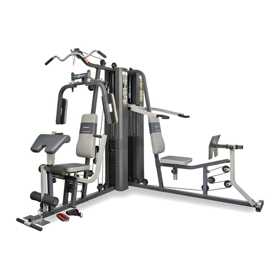
Marcy Platinum
Safety Notice
Corner Gym
GS 99
Resistance Chart
Model
GS 99
Retain This
Manual for
Reference
Jan-14-05
OWNER'S
IMPEX FITNESS PRODUCTS
MANUAL
14777 DON JULIAN RD., CITY OF INDUSTRY, CA 91746
Tel: (800) 999-8899 Fax: (626) 961-9966
www.impex-fitness.com
IBL
info@impex-fitness.com
Advertisement
Table of Contents

Related Manuals for Impex Marcy Platinum GS 99


Summary of Contents for Impex Marcy Platinum GS 99
- Page 1 NOTE: Please read all instructions carefully before using this product Table of Contents Marcy Platinum Safety Notice Corner Gym Hardware Pack GS 99 Assembly Instruction Parts List Resistance Chart Warranty Ordering Parts Model GS 99 Retain This Manual for Reference...
-
Page 2: Table Of Contents
ORDERING PARTS... 27 BEFORE YOU BEGIN Thank you for selecting the Marcy Platinum GS-99 CORNER GYM by IMPEX FITNESS PRODUCTS. For your safety and benefit, read this manual carefully before using the machine. As a manufacturer, we are committed to provide you complete customer satisfaction. -
Page 3: Important Safety Notices
AGE OF 35 OR PERSONS WITH PRE-EXISTING HEALTH PROBLEMS. READ ALL INSTRUCTIONS BEFORE USING ANY FITNESS EQUIPMENT. ASSUMES NO RESPONSIBILITY FOR PERSONAL INJURY OR PROPERTY DAMAGE SUSTAINED BY OR THROUGH THE USE OF THIS PRODUCT. SAVE THESE INSTRUCTIONS. IMPEX INC. -
Page 4: Hardware Pack
HARDWARE PACK... - Page 5 HARDWARE PACK...
- Page 6 HARDWARE PACK...
-
Page 7: Assembly Instructions
ASSEMBLY INSTRUCTION Tools Required Assembling the Machine: Two Adjustable Wrenches and Allen Wrenches NOTE: It is strongly recommended two or people assembling this machine to avoid possible injury. STEP 1 (See Diagram 1) A.) Place the Right Base Frame (#1) on a flat surface. Make sure there is enough space around to assemble the machine. - Page 8 STEP 2 (See Diagram 2) A.) Attach the Rear Vertical Frame (#4) to the Right Base Frame (#1). Attach the Left Base Frame (#2) to the Rear Vertical Frame. Align the holes and secure them with two M10 x 2 ¾”...
- Page 9 STEP 3 (See Diagram 3) A.) Attach the Right Vertical Beam (#3) to the Right Base Frame (#1). Secure it with two M10 x 2 ½” Carriage Bolts (#85), not tighten the Nuts and Bolts yet. B.) Attach the Right Seat Support (#7) to the Right Vertical Beam (#3). Secure it with one M10 x 2 ½”...
- Page 10 STEP 4 (See Diagram 4) A.) Slide fourteen Weight Plates (#44) onto the rear set of Guide Rods (#9). Make sure the groves on the Plates all face toward the back of the machine. Insert a Selector Rod (#29) into the center holes. Slide a Selector Stem (#45) onto the two Guide Rods. B.) Repeat Procedure A above to install the other fourteen Weight Plates onto the other two Guide Rods.
- Page 11 DIAGRAM 4...
- Page 12 STEP 5 (See Diagram 5) A.) Attach the Left Seat Support (#8) to the Left Vertical Beam (#5). Secure it with two M10 x 2 ½” Carriage Bolts (#85), one 4 3/8” x 1 ¾” Bracket (#73), two Ø ¾” Washers (#99), and two M10 Aircraft Nuts (#96).
- Page 13 STEP 6 (See Diagram 6) A.) Attach the Front Press Base (#10) to the Right Base Frame (#1). Secure it with one M10 x 9 ¼” Front Press Axle (#49), two Ø ¾” Washers (#99), and two M10 Aircraft Nuts (#96). B.) Attach two Front Press Frames (#13) onto the bracket on the Front Press Base.
- Page 14 STEP 7 (See Diagram 7) A.) Attach the Butterfly Support Frame (#11) to the front of Right Vertical Frame (#3). Attach the Butterfly Pulley Support (#12) to the back of Right Vertical Frame. Align the holes and secure them with two M10 x 2 ½” Carriage Bolts (#85), Ø ¾” Washers (#99), and M10 Aircraft Nuts (#96).
- Page 15 STEP 8 (See Diagram 8) A.) Attach the Vertical Press Frame (#20) to the Rear Vertical Frame (#4). Secure it with one M10 x 4 7/8” Vertical Press Axle (#48), two Ø ¾” Washers (#99), and two M10 x 5/8” Allen Bolts (#80).
- Page 16 CABLE LOOP DIAGRAM...
- Page 17 STEP 9 (See Cable Loop Diagram & Diagram 9) A.) Attach the 108” Upper Cable (#37) to the front opening on the Upper Frame (#6). Attach a Pulley (#56) to the opening. Secure it with one M10 x 2 3/8” Allen Bolt (#83), two Pulley Bushings (#55), and one M10 Aircraft Nut (#96).
- Page 18 STEP 10 (See Cable Loop Diagram & Diagram 10) A.) Clip one end of the 106” Butterfly Cable (#38) to the slot on the Left Butterfly Adjustment Frame. Draw the Cable through the slot then to the open left Swivel Pulley Bracket (#23). B.) Attach a Pulley (#56) to the bracket.
- Page 19 STEP 11 (See Cable Loop Diagram & Diagram 11) A.) Attach the 239” Front Press Cable (#36) to the lower opening on the Leg Developer (#19). Attach a Pulley (#56) to the opening. Secure it with one M10 x 2 3/8” Allen Bolt (#83), two Pulley Bushings (#55), and one M10 Aircraft Nut (#96).
- Page 20 DIAGRAM 11...
- Page 21 STEP 12 (See Diagram 12) A.) Attach end of the 357” Leg Press Cable (#39) to the bracket on the Left Seat Support (#8). Secure the Cable to the bracket with one M10 x 1” Allen Bolt (#81), two Ø ¾” Washers (#99), and one M10 Aircraft Nut (#96).
- Page 22 DIAGRAM 12...
- Page 23 STEP 13 (See Diagram 13) A.) Place a Seat Pad (#32) onto the Seat Incline Adjustment (#16). Secure it with two M8 x 1 5/8” Allen Bolts (#92) and Ø 5/8” Washers (#98). B.) Insert the Seat Incline Adjustment into the opening on the Left Seat Support. Secure it with a M18 Lock Knob (#61) at desired position.
- Page 24 STEP 14 (See Diagram 14) A.) Place a Seat Pad (#32) onto the Right Seat Support (#7). Secure it with two M8 x 2 3/8” Allen Bolts (#91) and 5/8” Washers (#98). B.) Attach a Backrest Board (#33) to the Right Vertical Beam (#3). Secure it with two M8 x 2 3/8” Allen Bolts (#91) and 5/8”...
- Page 25 STEP 15 (See Diagram 15) A.) Securely tighten all the nuts and bolts previously installed. B.) To maximize the performance of the gym, it is recommended to use light lubricant such as WD-40 on the two chromed rods which the weight plates slide up and down to minimum frictions.
-
Page 26: Parts List
PARTS LIST KEY NO. DESCRIPTION Right Base Frame Left Base Frame Right Vertical Beam Rear Vertical Frame Left Vertical Beam Upper Frame Right Seat Support Left Seat Support Guide Rod Front Press Base Butterfly Support Frame Butterfly Pulley Support Front Press Frame Leg Press Frame Leg Press Adjustment Frame Seat Incline Adjustment... -
Page 27: Resistance Chart
GS 99 WEIGHT RESISTANCE CHART Station Low Pulley Lat Pull Butterfly Leg Press Front Press Vertical Press Station Low Pulley Lat Pull Butterfly Leg Press Front Press Vertical Press *Numbers are approximate. Actual weight may vary. *Number *Number *Number s are approximate. Actual weight may vary. -
Page 28: Warranty
IMPEX Customer Service Department at 1-800-999-8899. All freights on products returned to IMPEX must be prepaid by the customer. This warranty does not extend to any product or damage to a product caused by or attributable to freight damage, abuse, misuse, improper or abnormal usage or repairs not provided by an IMPEX authorized service center or for products used for commercial or rental purposes.