Edirol V-4 Owner's Manual
4-channel video mixer
Hide thumbs
Also See for V-4:
- Owner's manual (108 pages) ,
- Specifications (2 pages) ,
- Specifications (2 pages)
Table of Contents
Advertisement
Quick Links
Owner's Manual
Before using this unit, carefully read the sections entitled: "USING THE UNIT SAFELY"
and "IMPORTANT NOTES" (Owner's Manual p. 3–4; Owner's Manual p. 5–6). These
sections provide important information concerning the proper operation of the unit.
Additionally, in order to feel assured that you have gained a good grasp of every
feature provided by your new unit, Owner's manual should be read in its entirety. The
manual should be saved and kept on hand as a convenient reference.
Copyright © 2003 ROLAND CORPORATION
All rights reserved. No part of this publication may be reproduced in any form without
the written permission of ROLAND CORPORATION.
Advertisement
Table of Contents

Related Manuals for Edirol V-4


Summary of Contents for Edirol V-4
- Page 1 Owner’s manual should be read in its entirety. The manual should be saved and kept on hand as a convenient reference. Copyright © 2003 ROLAND CORPORATION All rights reserved. No part of this publication may be reproduced in any form without the written permission of ROLAND CORPORATION.
- Page 2 For the U.K. IMPORTANT: THE WIRES IN THIS MAINS LEAD ARE COLOURED IN ACCORDANCE WITH THE FOLLOWING CODE. BLUE: NEUTRAL BROWN: LIVE As the colours of the wires in the mains lead of this apparatus may not correspond with the coloured markings identifying the terminals in your plug, proceed as follows: The wire which is coloured BLUE must be connected to the terminal which is marked with the letter N or coloured BLACK.
-
Page 3: Using The Unit Safely
• Do not allow any objects (e.g., flammable material, specific instructions directing you to do so). Refer coins, pins); or liquids of any kind (water, soft all servicing to your retailer, the nearest Roland/ drinks, etc.) to penetrate the unit. Edirol Service Center, or an authorized Roland/ Edirol distributor, as listed on the “Information”... - Page 4 • Before using the unit in a foreign country, consult all dust and other accumulations away from its with your retailer, the nearest Roland/Edirol prongs. Also, disconnect the power plug from the Service Center, or an authorized Roland/Edirol power outlet whenever the unit is to remain distributor, as listed on the “Information”...
-
Page 5: Important Notes
• Using the unit near power amplifiers (or other equipment lost. Roland /Edirol assumes no liability concerning such containing large power transformers) may induce noise or loss of data. - Page 6 When the unit is grounded, a slight noise may problem. Roland or Edirol is not responsible to any appear, depending on the particulars of your installation. medical problem of yourselves or audiences/spectators If you are unsure of the connection method, contact the caused by such video sequence.
-
Page 7: Table Of Contents
Contents USING THE UNIT SAFELY ................3 IMPORTANT NOTES ..................5 Contents ......................7 Welcome ......................9 Features of the V-4 ..................10 Four-channels of video inputs........................... 10 Two independent frame synchronizers ........................10 High-quality digital effects ............................10 Simple operation ................................. 10 Preview function ................................. 10 Switching and effects synchronized to music...................... - Page 8 Contents Switching in synchronization with music ...........37 Using BPM sync to switch images..........................37 Using the tap (TAP) function to switch images...................... 38 Applying an effect on the music ..............39 Using BPM sync to apply an effect ........................... 39 Using the tap (TAP) function to apply an effect..................... 39 Editing the front panel assignments............40 Changing the assignment of the mix button (MIX) ....................
-
Page 9: Welcome
Welcome Thank you, and congratulations on your choice of the Edirol V-4. The V-4 is a video mixer/effects processor that delivers image quality rivaling professional equipment, and provides four channels of video input. With a rich array of inputs and easy operation, the V-4 allows performances and presentations that include images to be made more expressive than ever before. -
Page 10: Features Of The V-4
Control from external MIDI devices The V-4 provides MIDI connectors. An external MIDI device can control effects and switching images. Setup is particularly easy if a Roland or Edirol product that supports V-LINK is connected—simply press the V-LINK button on the control device. -
Page 11: What Is V-Link
Audio output Mixer/speaker Video output Remote control TV/projector, etc. V-LINK Roland/Edirol product that supports V-LINK Audio output Mixer/speaker Remote control Video output TV/projector, etc. V-LINK... -
Page 12: Before You Begin
Before you begin Before you begin Check the included items The V-4 is shipped with the following items. Please make sure that nothing is missing. The V-4 itself AC adaptor and power cable Owner’s manual Four screws to affix Video Fader (spare) -
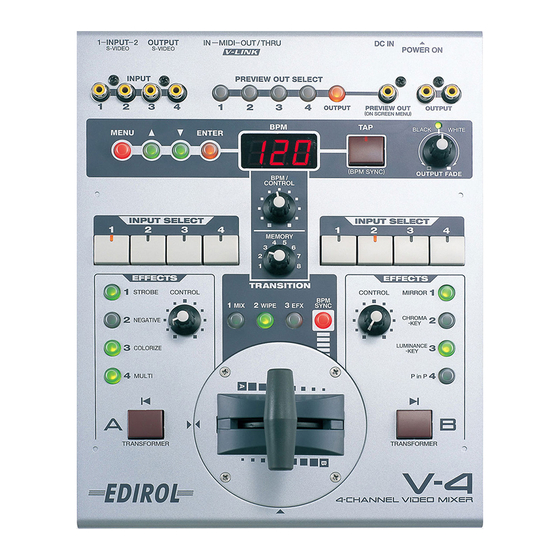
Page 13: Names Of Things And What They Do
Before you begin Names of things and what they do Rear Panel 4. MIDI OUT connector (MIDI OUT) 5. MIDI IN connector (MIDI IN) 1. Power button (POWER) 7. S-video input jack (S-VIDEO INPUT) 6. S-video output jack (S-VIDEO OUTPUT) 2. -
Page 14: Front Panel
Before you begin Power cable hook Use this hook to retain the power cable so that it will not be accidentally unplugged. MIDI OUT connector (MIDI OUT) MIDI messages input from an external device are output without change (“thru-ed”) from this connector. - Page 15 Before you begin WHITE to fade the final output to white. Turn the dial toward BLACK to fade the final output to black. 16. Channel A input selector (INPUT SELECT) (see p. 23) This button selects the image that will be input to channel A of the video mixer. 17.
-
Page 16: About Ground Terminal
When the unit is grounded, a slight noise may result, depending on the particulars of your installation. If you are unsure of the connection method, contact nearest Service Center, or authorized distributor, as listed on the Roland/Edirol Roland/Edirol “Information” page. Ground Terminal Unsuitable places for connection •... -
Page 17: Connecting Peripheral Devices
Connecting peripheral devices Connecting peripheral devices This section explains how to connect your peripheral devices to the V-4. You can connect up to four video playback devices (sources). Here’s how to connect sources such as a video camcorder, VCR, DVD player, or DV- 7PR, and play them back to create an impressive video performance. -
Page 18: Video Signal Flow
Connecting peripheral devices Video signal flow The video signals received from the four input jacks are assigned to channels A or B of the video mixer. (These assignments are made manually.) The signal of A and B channels are processed by the video mixer section, and sent via the output fader to the output jack. -
Page 19: Turning The Power On/Off
Turning the power on/off Turning the power on/off Turning the power on Check the power cable Make sure that the cable from the AC adaptor is firmly plugged into the V-4. Press the POWER button. Press the POWER button located on the rear panel of the V-4. It will take approximately five seconds for the V-4 to initialize itself and begin operating. -
Page 20: Checking The Inputs And Outputs
Checking the inputs and outputs Checking the inputs and outputs Checking the final output Here’s how to check that the signal from each source device is correctly being input to the V-4, and is correctly being output to the TV or projector as final output. Play back the source device. -
Page 21: About The Display On Preview Monitor
Checking the inputs and outputs Switch the output channel Try switching the channel that is being output to the V-4’s preview monitor. Press the preview select buttons (1 through 4 and OUTPUT) one after another, and verify that the image being output to your TV monitor changes accordingly. -
Page 22: About The Memory Dial (Memory)
About the Memory dial (MEMORY) About the Memory dial (MEMORY) The V-4 has a memory dial that lets you store up to eight states of the panel settings. Setting 1 is fixed at the factory settings, but you can store user settings in 2 through 8. When the memory dial is at 1, the effect names printed on the panel will match the actual functions. -
Page 23: Switching Two Images
Switching two images Switching two images Here’s how to switch the images being input to channel A and channel B. Switching by Cut Set the memory dial (MEMORY) to 1. To return the V4 state to the factory settings, turn the dial all the way to the left to select the #1 position. -
Page 24: Switching With Dissolve
Switching two images Release the transformer button (TRANSFORMER) Release your finger from the transformer button you pressed. Notice that the image displayed on your TV monitor (or projector) has returned to the previous image. Switching with dissolve “Dissolve” is the effect of switching images using a gradual fade. You can create this effect by mixing two images. -
Page 25: Using Fade-To-White Or Fade-To-Black
Switching two images Select the input images for A and B. From inputs 1 through 4, select the images that will be input to channel A and channel B. If the same image is being input to both channels A and B, you will not notice any change when you switch between channels. -
Page 26: Compositing Two Images
Compositing two images Compositing two images On the V-4 you can use Picture In Picture or Chroma Key/Luminance Key to composite the images of channels A and B. Using Picture In Picture to composite images Here’s how you can miniaturize the image of channel B and overlay it on the channel A image. Use this when you want to output two images simultaneously. -
Page 27: Using Chroma Key To Composite Images
Compositing two images Turn the effect off Press the button again to turn the effect off. Some effects cannot be used simultaneously. You can change the P in P effect settings to modify the location and size of the superimposed image (the secondary image). -
Page 28: Using Luminance Key To Composite Images
Compositing two images Turn the control dial. Parameter of Chroma Key (level of extraction) gradually changes. If Chroma Key button is not blinking, you cannot change the parameter with the control dial. Move the video fader Moving the video fader will control the appearance and disappearance of the background image. Turn the effect off Press the button again to turn the effect off. - Page 29 Compositing two images Select channel A image. Play back the image that you want to use as the background. Select channel B image. Input image to overlay into channel B. The image for Luminance Key should have clear contrast of light and dark.
- Page 30 Compositing two images You cannot composite images via Luminance Key if there is no light or dark aspects in the image to key off of. It may be difficult to extract correctly if contrast of light/dark is not sufficient or consistent.
-
Page 31: Changing The Color Of The Image
Changing the color of the image Changing the color of the image Applying the Negative effect Here’s how to apply the Negative effect to the image being input to channel A. The “Negative” effect inverts the brightness and color of the image from positive to negative. Set the memory dial (MEMORY) to 1. -
Page 32: Applying The Colorize Effect
Changing the color of the image Turn the control dial. Turn the control dial. The brightness and color of the image will be inverted to a negative. Turn the effect off Press the button again to turn the effect off. Applying the Colorize effect Here’s how to apply the Colorize effect to the image being input to channel A. - Page 33 Changing the color of the image Some effects cannot be used simultaneously. In addition to the Negative and Colorize effects, the color of the image can also be modified using the Posterize effect. To use the Posterize effect, you will need to assign it to an effect button of channel A or channel B.
-
Page 34: Changing The Motion Of The Image
Changing the motion of the image Changing the motion of the image Applying strobe motion Here’s how to apply a Strobe Motion effect to the image being input to channel A. “Strobe Motion” is an effect that thins-out the frames of the image, producing the impression that the motion is being halted at intervals. -
Page 35: Applying The Multi Or Mirror Effects
Applying the Multi or Mirror effects Applying the Multi or Mirror effects Applying the Multi effect Here’s how the image that is input to channel A can be divided on the screen. You can divide the image vertically, horizontally, or both vertically and horizontally. Set the memory dial (MEMORY) to 1. -
Page 36: Applying The Mirror Effect
Applying the Multi or Mirror effects Applying the Mirror effect Here’s how the image that is input to channel B can be divided and inverted. The result is as though a mirror were placed in the center of the screen. The image can be inverted vertically, horizontally, or both vertically and horizontally. -
Page 37: Switching In Synchronization With Music
Switching in synchronization with music Switching in synchronization with music The V-4 can switch images in synchronization with the beat of the music. You can use the BPM or TAP functions to switch images as you see in VJ performances. Using BPM sync to switch images You can use BPM (Beats Per Minute) to specify the timing at which images will be switched. -
Page 38: Using The Tap (Tap) Function To Switch Images
Switching in synchronization with music Using the tap (TAP) function to switch images As an alternative to specifying the BPM numerically, you can use the tap button (TAP) to specify the timing at which the images will switch. Input images to channels A and B. Use the channel A and B input selectors to input images into each channel. -
Page 39: Applying An Effect On The Music
Applying an effect on the music Applying an effect on the music The V-4 cannot only switch images but can also apply effects in time with music. You can use the BPM or TAP functions to apply effects that are synchronized with the music, as in a VJ performance. -
Page 40: Editing The Front Panel Assignments
Editing the front panel assignments Editing the front panel assignments As explained earlier, the functions assigned to the buttons and dials of the V-4 can be stored in memory and accessed via the memory dial (MEMORY). (Note: The assignment for dial position number 1 is fixed at the factory and not assignable.) You can edit and save the assignments of the following buttons and dials: •... - Page 41 Editing the front panel assignments...
-
Page 42: Changing The Assignment Of The Mix Button (Mix)
Editing the front panel assignments Changing the assignment of the mix button (MIX) With the factory settings, mix (MIX: dissolve) is assigned to this button for all eight positions of the memory dial. Here’s how to assign a different type of transition effect to the mix button for one of the dial positions. -
Page 43: Changing The Assignment Of The Wipe Button (Wipe)
Editing the front panel assignments Select the transition effect. Use the cursor buttons to select the type of transition effect. With an effect selected (blinking) and the video fader set in the center position, the output screen will show the type of transition effect that is selected. -
Page 44: Changing The Assignment Of The Efx Button (Efx)
Editing the front panel assignments Press the enter button (ENTER). Press the enter button (located at the right of the cursor buttons) to make your selection. The preview screen display will change. Select the transition effect. Use the cursor buttons to select the type of transition effect. With an effect selected (blinking) and the video fader set in the center position, the output screen will show the type of transition effect that is selected. - Page 45 Editing the front panel assignments Press the EFX button (EFX) The button lights up when pressed. Press the menu button (MENU). Press the menu button (MENU) located in the upper left of the panel. The settings edit menu will appear on the TV screen connected to the preview output. Select “EFX.”...
-
Page 46: Changing The Assignment Of The Output Fade Dial (Output Fade)
Editing the front panel assignments Return to the previous screen. When you have selected an effect, press the menu button to return to the previous screen. Press the button twice to exit the menu screen and return to the previous screen. Changing the assignment of the output fade dial (OUTPUT FADE) With the factory settings, and when the memory dial is set to number 1, turning the output fade... - Page 47 Editing the front panel assignments Press the enter button (ENTER). Press the enter button (located at the right of the cursor buttons) to make your selection. The preview screen display will change. Select the fade pattern. Use the cursor buttons to select the type of fade pattern. With a pattern selected (blinking), turn the output fade dial to see the currently selected fade pattern occur in the output screen.
-
Page 48: Changing The Assignments Of The Channel A And B Effect Buttons (Effects)
Editing the front panel assignments Changing the assignments of the channel A and B effect buttons (EFFECTS) With the factory settings, effect buttons 1 through 4 of channels A and B are assigned the following effects: Channel A: 1 Strobe (STROBE) 2 Negative (NEGATIVE) 3 Colorize (COLORIZE) 4 Multi (MULTI) - Page 49 Editing the front panel assignments Press the enter button (ENTER). Press the enter button (located at the right of the cursor buttons) to make your selection. The preview screen display will change displaying a screen where you can choose the button whose assignment will be changed.
-
Page 50: Changing The Assignment Of The Bpm Sync Button (Bpm Sync)
Editing the front panel assignments If you select an effect with the “*” mark after the effect name, the effect value can be changed with the control dial. Return to the previous screen. When you have made your selection, press the menu button to return to the previous screen. Press the button three times to exit the menu screen and return to the previous screen. -
Page 51: Changing The Assignment Of The Channel A/Channel B Transformer Buttons (Transformer)
Editing the front panel assignments Select “MODE” or “SPEED.” Use the cursor buttons to choose whether it is the mode or the speed of the transition that you want to change. Choose “MODE” if you want to change the transition from a “cut” to one that incorporates some kind of effect, such as “wipe.”... - Page 52 Editing the front panel assignments Select “Transformer.” Use the cursor buttons to select “Transformer.” The memory dial number you select is displayed following “Transformer.” If you have selected memory number 2, this will indicate [Mem2]. Press the enter button (ENTER). Press the enter button (located at the right of the cursor buttons) to make your selection.
-
Page 53: Protecting The Memory
Editing the front panel assignments Protecting the memory By turning on Memory Protect, you can prevent any accidental changes from being made to the assignments you made for memory numbers 2 through 8. Press the menu button (MENU). Press the menu button (MENU) located in the upper left of the panel. The menu will appear on the TV screen connected to the preview output. -
Page 54: Copying Or Exchanging Memories
Editing the front panel assignments Return to the previous screen. When you have finished making settings, press the menu button to return to the previous screen. Press the button three times to exit the menu screen and return to the previous screen. Copying or exchanging memories You can copy the contents of the currently selected memory to another memory, or exchange them with another memory. -
Page 55: Recalling The Factory Settings
Editing the front panel assignments Press the enter button (ENTER). When you have specified the operation, press the enter button. The display will indicate “Push [ENTER]” so press the enter button once again. The selected operation will be executed. Return to the previous screen. After you have executed the operation, press the menu button to return to the previous screen. - Page 56 Editing the front panel assignments Press the enter button (ENTER) Pressing the enter button will reinitialize the V4 to its Factory Presets. All the settings and adjustments will return to factory preset status.
-
Page 57: Control The V-4 From An External Device
Control the V-4 from an external device Control the V-4 from an external device Using V-LINK to control the V-4 You can connect the V-4 with a V-LINK compatible device made by Roland or Edirol, and control the V-4 remotely. ■ What is V-LINK? V-LINK ( ) is a function that allows images to be synchronized to music. -
Page 58: Using Midi To Control The V-4
Control the V-4 from an external device ■ Using V-LINK For details on how to turn V-LINK on/off, refer to the owner’s manual of the V-LINK compatible device that you intend to connect to the V-4. When you turn V-LINK on, the indication “V-LINK” will appear in the preview monitor. - Page 59 Control the V-4 from an external device * System for auto switching and effects controlled by MIDI sequencer Source Devices MIDI Sound Module Audio DV-7PR MIDI MIDI MIDI Sequencer V-LINK makes it easy to control the basic functions of the V-4. Even if you are using a device that does not support V-LINK, you can make transmission and reception settings so that the V-4 can be controlled from a musical instrument or other external device.
-
Page 60: Midi Settings
Control the V-4 from an external device ■ MIDI settings You will need to make settings on the V-4 so that it will receive control messages from an external MIDI device. The procedure is as follows. ■ Setting the MIDI transmit channel (MIDI Tx Channel) This setting specifies the MIDI channel that will be used to send control messages. - Page 61 Control the V-4 from an external device ■ Setting the MIDI receive channel (MIDI Rx Channel) This setting specifies the MIDI channel that will be used to receive control messages. Press the menu button (MENU). Press the menu button to display the V-4 menu on the preview screen. Select “MIDI Setup.”...
- Page 62 Control the V-4 from an external device ■ Making other MIDI settings You can use the same procedure to make other MIDI settings. In particular, the following buttons and dials can be controlled via MIDI: • Channel A effect buttons 1–4 •...
- Page 63 Control the V-4 from an external device MIDI Setup MIDI Tx Channel 1 - 16 MIDI transmit channel setting MIDI Tx Channel 1 - 16/OFF MIDI receive channel settings Out/Thru MIDI Out/Thru Switch MIDI out/thru setting V-LINK Switch Off/On V-LINK on/off setting Note Mode On/Off Off/On Note mode on/off setting...
-
Page 64: Making Various Settings
Making various settings Making various settings The V-4’s video mixer lets you adjust the brightness and color of channels A and B independently. With the factory settings, both channels are set to typical settings, and you do not need to change these settings unless you wish. - Page 65 Making various settings Return to the previous screen. When you have finished making the setting, press the menu button to return to the previous screen. If you press the menu button three times, you will exit the menu screens and return to the previous screen.
-
Page 66: Calibrating The Video Fader
Calibrating the video fader Calibrating the video fader With the factory settings, moving the V-4’s video fader all the way to the A position will output 100% of channel A, and moving it all the way to the B position will output 100% of channel B. If for some reason, moving the video fader all the way to A or B does not output 100% of the image, you can use the following procedure to automatically calibrate the fader. - Page 67 Calibrating the video fader Press the menu button (MENU). Press the menu button to display the menu in the preview screen. Select “Utility.” Use the cursor buttons to select “Utility.” Then press the enter button to display the “Utility” settings. Select “Video Fader Calibrate B.”...
-
Page 68: Using The V-4 In Presentation Mode
Using the V-4 in Presentation mode Using the V-4 in Presentation mode The V-4 has two modes; Normal mode and Presentation mode. The preceding chapters have explained operation in Normal mode. This chapter explains how to use the V-4 in Presentation mode. -
Page 69: Switching To Presentation Mode
Using the V-4 in Presentation mode Switching to Presentation mode To switch from Normal mode to Presentation mode, turn off the power of the V-4. Then hold down channel A input select buttons 1 and 4, and press the power button. Once you switch to Presentation mode, that setting will be preserved. - Page 70 Using the V-4 in Presentation mode Switch the background image. Successively press the channel A input select buttons 1 through 4 to switch the image. Apply the Picture In Picture function. Set the memory dial to number 2. Picture In Picture will be applied. Apply other effects to composite two images.
-
Page 71: Switching Between Ntsc And Pal
Switching between NTSC and PAL Switching between NTSC and PAL The V-4 can be switched to support either NTSC or PAL format signals. To start up in PAL mode, hold down preview select button 1 and “OUTPUT,” and press the power button. The next time you start up, you can simply press the power button to start up in PAL mode. -
Page 72: Changing The Video Fader Orientation
Changing the video fader orientation Changing the video fader orientation The V-4’s T-bar style video fader may be installed in either the horizontal or vertical orientation depending on your preference. When shipped, the video fader is installed for vertical operation. If you prefer to operate the fader horizontally, you can turn the video fader 90 degrees. - Page 73 Changing the video fader orientation If you attempt to rotate the vide fader panel further than 90 degrees, the internal cable may be damaged. Note the location of the triangle symbols, and do not rotate the video fader panel further than 90 degrees.
-
Page 74: Troubleshooting
Troubleshooting Troubleshooting If you suspect a malfunction, please check your system once again, taking note of the points listed below. If it still does not function correctly, contact an Edirol Service Center or the dealer where you purchased the unit. Operating the video fader does not switch the image If the same image is being input to channels A and B, operating the T-bar will not produce any change in the output image. -
Page 75: Menu List
Menu List Menu List (Trans1) [Mem2-8] 001:Mix Mix(Dissolve) Wipe (Trans2) [Mem2-8] 002:Wipe01 Hard-edged wipes (Trans3) [Mem2-8] 073:Wipe72 074:SWipe01 Soft-edged wipes 145:SWipe72 146:MWipe01 Multi-border wipes 217:MWipe72 218:Key01 Transition effects using key extraction 221:Key04 222:Slide01 Slide in/out 248:Slide27 Parameter of effects marked by an asterisk* can be varied by the control dial A-Efx1 Effects-A [Mem2-8]... - Page 76 Menu List Parameter of effects marked by an asterisk* can be varied by the control dial A-Efx1 Effects-A [Mem2-8] 57:CHROMAKEY Chroma key A-Efx2 58:CHROMAKEY A-Efx3 59:MULTI-H1 Horizontally divided A-Efx4 multiscreen 63:MULTI-H Effects-B [Mem2-8] B-Efx1 64:MULTI-V1 B-Efx2 Vertically divided multiscreen B-Efx3 68:MULTI-V B-Efx4 69:MULTI-HV1...
- Page 77 Menu List A-Efx1 Effects-A [Mem2-8] 89:PinP-1 A-Efx2 Picture In Picture 96:PinP-8 A-Efx3 A-Efx4 Effects-B [Mem2-8] B-Efx1 B-Efx2 B-Efx3 B-Efx4 HPosi 000 PinP1-8 HPosi Adjust horizontal location of PinP HPosi 153 VPosi 000 PinP1-8 VPosi Adjust vertical location of PinP VPosi 207 4:3 HVSize 000 PinP1-8 4:3 HVSize Adjust size at fixed aspect ratio...
- Page 78 Menu List Transformer [Mem2-8] 01:none-none No function 02:Trans-Trans Output the image of pressed channel as long as button is held. 03:A<->9-9<->B 04:A<->8-8<->B 05:A<->7-7<->B 06:A<->6-6<->B Switch between A and B each time you press the button. 07:A<->5-5<->B 0--9 indicates the duration of the transition. Higher numbers produce a longer transition.
- Page 79 Menu List BPM Sync [Mem 2-8] Mode Direct A-B Transition by cut Select BPM sync mode TransitionA-B Transition applying effect BPMx1/4 Speed Transition at 1/4 speed of BPM Transition at 1/2 speed of BPM BPMx1/2 Specify BPM sync speed BPMx1 Transition at speed of BPM Transition at double speed of BPM BPMx2...
- Page 80 Menu List Memory Edit Copy Mem1->Mem2 Copy the contents of the selected memory dial setting to another number Copy Mem8->Mem8 Copy the contents of the selected memory dial Copy Mem1->All setting to all numbers Exchange Mem1->Mem2 Exchange the contents of the selected memory dial setting with another number Exchange Mem8->Mem8 MIDI Setup...
- Page 81 Menu List Utility V-4 Mode Normal Mode Operate in Normal mode Presen Mode Operate in Presentation mode Memory Protect Memory protect is off Memory protect is on -048 Video Sync Threshold Adjust video synchronization sensitivity +079 -060 VideoA Bright Adjust Adjust the brightness of channel A +061 -010...
- Page 82 Menu List Utility OutFade White Level Specify the white level of the output fader OutFade Black Level Specify the black level of the output fader Preview Display Mode No Display Turn off the preview display Mode 1 Mode 2 Specify the mode of the preview display Mode 3 Preview Switch Pattern Manual...
-
Page 83: Main Specifications
Main specifications Main specifications Video format NTSC or PAL (ITU601) Video sampling rate 13.5 MHz, 4:2:2 (Y: B-Y:R-Y), 8-bit Video input S-video: 4-pin mini DIN type x 2 jacks (inputs 1 or 2) Video (composite): RCA pin type x 4 (inputs 1-4; however if S-video is simultaneously input to 1/ 2, S-video takes priority) Video output S-video: 4-pin mini DIN type x 1 jack... - Page 84 Main specifications Dimensions 225 mm (W) x 295 mm (D) x 105 mm (H) Weight 2.3 kg Included items AC adaptor Owner’s manual T-bar attachment screws x 4 pcs. (spares)
-
Page 85: Examples Of Using The V-4
Examples of using the V-4 Examples of using the V-4 Using the V-4 at an event Here’s an example of using the V-4 to switch between multiple live images and sources such as a video tape, as might be used at events such as exhibitions or performances. Live source Preview Large display (plasma) -
Page 86: Using The V-4 At A Concert Or Vj Performance
Examples of using the V-4 Using the V-4 at a concert or VJ performance You can project the output image on a large screen such as the stage backdrop, and create a video performance that follows the music. Images from the DV-7PR can be mixed with multiple live images. -
Page 87: Using The V-4 At A Presentation
Examples of using the V-4 Using the V-4 at a presentation You can use the V-4 to switch between live images and VTR/DVD output, or add images/text from a personal computer. If you are using a personal computer that does not have a video output, you will need to use a scan converter to convert the computer’s VGA output into a video signal. -
Page 88: Using Bgv Output With A Musical Performance (Example Of Using V-Link)
Background video (BGV) can be controlled while you play a musical instrument. You can control images without affecting the normal capabilities of the instrument. In particular if you are using a device that supports Roland/Edirol V-LINK ( ), you can press a single button to quickly and easily make settings for controlling images. -
Page 89: Midi Implementation
MIDI implementation ❍Modulation (controller number 1) Model:V-4 Version:1.000 Date:Dec.10.2002 Status 2nd byte 3rd byte Symbol Meaning Range ---------------------------------------------------------------------------------------------------------------------- MIDI channel 0H–FH (ch.1–ch.16) ❍Breath-type (controller number 2) control value, velocity value, etc. 00H–7FH (0–127) Status 2nd byte 3rd byte only in the case of Note-on Velocity 01H–7FH (1–127) note number 00H–7FH (0–127) -
Page 90: Program Change
3rd byte ii= ID number: An ID number (manufacturer ID) that indicates the manufacturer to which the exclusive message belongs. Roland’s manufacturer ID is 41H. ID numbers 7EH and 7FH are used for Universal Non-realtime Messages (7EH) and Universal Realtime Messages mm, ll= pitch bend value:00 00H - 40 00H - 7F 7FH (-8192 - 0 -+8191) (7FH) to extend the MIDI specification. - Page 91 MIDI implementation ❍General Purpose Controllers 1–4 (controller numbers 16-19) 2. MIDI messages transmitted from MIDI Status 2nd byte 3rd byte 10H - 13H * If MIDI Thru is ON, MIDI messages received at MIDI IN are re-transmitted without ❍Hold 1 (controller number 64) change from MIDI OUT.
-
Page 92: Parameter Address Map
MIDI Implementation 3. Parameter Address Map ■3-1. V-4 (Model ID= 00H 5BH) * Addresses marked by # are sent as two bytes; an upper nibble (upper 4 bits) and lower nibble (lower 4 bits). Example) If the original data is channel B, 0BH is transmitted as the first byte. The next byte transmitted is 0CH. For reception, this is ignored if two bytes are not received together. +————————————————————————————————————————————————————————————————+ |Start Address |Description... - Page 93 MIDI Implementation ■3-2. V-LINK (Model ID= 00H 51H) * Addresses marked by # are sent as two bytes; an upper nibble (upper 4 bits) and lower nibble (lower 4 bits). Example) If the original data is channel B, 0BH is transmitted as the first byte. The next byte transmitted is 0CH. For reception, this is ignored if two bytes are not received together. * If –...
- Page 94 ■Decimal and hexadecimal conversion table calculation Roland exclusive messages (RQ1, DT1) contain a checksum following the data (after F7), (The letter “H” follows numbers in hexadecimal notation.) which can be used to check whether the message was received correctly. The checksum MIDI uses hexadecimal notation in 7-bit units to indicate data values and addresses and value is derived from the address and data (or size) of the transmitted exclusive message.
- Page 95 MIDI Implementation ■Factory Setting of V-LINK ●A ch effect 3 This specifies effect 3 on/off and the parameter for channel A in Normal mode or the base The factory setting of V-LINK (receipt of V-LINK ON message only) is as follows. channel in Presentation mode.
-
Page 96: Midi Implementation Chart
MIDI Implementation MIDI Implementation 4-Channel Video Mixer Model V-4 Date : Dec. 13, 2002 MIDI Implementation Chart Version : 1.00 Function... Transmitted Recognized Remarks Basic Default 1-16 1-16 Channel Changed 1-16 1-16 Default Mode 3 Mode 3 Mode Messages Altered *************** Note Operational only when... -
Page 97: Transition Effects List
Transition Effects List Factory-default Transition effects assignments Factory-default Transition effects assignments... -
Page 98: Mix Effects
Transition Effects List Mix Effects The effect gradually blends the picture into another. Wipe Effects The effects like windshield wiper on a car. The present picture is wiped off as it changes to another... Hard Edge type... - Page 99 Transition Effects List Soft Edge Type...
- Page 100 Transition Effects List...
- Page 101 Transition Effects List Multi Border Type...
-
Page 102: Luminance Key
Transition Effects List Luminance Key The bright or dark part of present picture gradually changes to another. The dark part of B ch picture gradually The blight part of B ch picture changes to A ch picture. gradually changes to A ch picture. The bright part of A ch picture The dark part of A ch picture gradually gradually changes to B ch picture. -
Page 103: Slide Effects
Transition Effects List Slide Effects The effect to slide out the preset picture and in the anothser. Normal Type Sequential Type... -
Page 104: The Effects Tha Cannot Be Used Simultanously
Transition Effects List The effects tha cannot be used simultanously... -
Page 105: Index
Index BPM control dial ............15 Output fade dial ............14 BPM indicator ..............14 BPM sync ................ 37 PAL .................. 71 BPM sync button ............15 panel assignments ............40 PCR-30/50 ..............57 Calibrating ..............66 Picture In Picture ............26 Chroma Key .............. - Page 106 Index ...MEMO...
- Page 107 Index ...MEMO...
- Page 108 Index ...MEMO...
- Page 109 Index ...MEMO...
- Page 110 Index ...MEMO...
- Page 111 For EU Countries This product complies with the requirements of EMC Directive 2004/108/EC. For the USA FEDERAL COMMUNICATIONS COMMISSION RADIO FREQUENCY INTERFERENCE STATEMENT This equipment has been tested and found to comply with the limits for a Class B digital device, pursuant to Part 15 of the FCC Rules.
- Page 112 Information When you need repair service, call your nearest EDIROL/Roland Service Center or authorized EDIROL/Roland distributor in your country as shown below. CZECH REP. HUNGARY CENTRAL/LATIN OCEANIA ASIA Roland East Europe Ltd. CZECH REPUBLIC AMERICA Warehouse Area ‘DEPO’ Pf.83 DISTRIBUTOR s.r.o...