Table of Contents
Advertisement
Safe Operation Practices • Set-Up • Operation • Maintenance • Service • Troubleshooting • Warranty
O
'
M
peratOr
s
anual
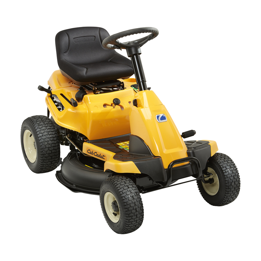
CC 30
WARNING
READ AND FOLLOW ALL SAFETY RULES AND INSTRUCTIONS IN THIS MANUAL
BEFORE ATTEMPTING TO OPERATE THIS MACHINE.
FAILURE TO COMPLY WITH THESE INSTRUCTIONS MAY RESULT IN PERSONAL INJURY.
CUB CADET LLC, P.O. BOX 361131 CLEVELAND, OHIO 44136-0019
Printed In USA
Form No. 769-09354
(November 19, 2013)
Advertisement
Table of Contents

Related Manuals for Cub Cadet CC 30


Summary of Contents for Cub Cadet CC 30
- Page 1 READ AND FOLLOW ALL SAFETY RULES AND INSTRUCTIONS IN THIS MANUAL BEFORE ATTEMPTING TO OPERATE THIS MACHINE. FAILURE TO COMPLY WITH THESE INSTRUCTIONS MAY RESULT IN PERSONAL INJURY. CUB CADET LLC, P.O. BOX 361131 CLEVELAND, OHIO 44136-0019 Printed In USA Form No. 769-09354...
-
Page 2: Table Of Contents
See How-to Maintenance and Parts Installation Videos at www.cubcadet.com/tutorials ◊ Call a Customer Support Representative at (800) 965-4CUB ◊ Locate your nearest Cub Cadet Dealer at (877) 282-8684 ◊ Write us at Cub Cadet LLC • P.O. Box 361131 • Cleveland, OH • 44136-0019... -
Page 3: Safe Operation Practices
Important Safe Operation Practices WARNING! This symbol points out important safety instructions which, if not followed, could endanger the personal safety and/or property of yourself and others. Read and follow all instructions in this manual before attempting to operate this machine. Failure to comply with these instructions may result in personal injury. - Page 4 Slope Operation A missing or damaged discharge cover can cause blade contact or thrown object injuries. Slopes are a major factor related to loss of control and tip-over Stop the blade(s) when crossing gravel drives, walks, or accidents which can result in severe injury or death. All slopes roads and while not cutting grass.
- Page 5 Service Children Tragic accidents can occur if the operator is not alert to the Safe Handling of Gasoline: presence of children. Children are often attracted to the machine and the mowing activity. They do not understand To avoid personal injury or property damage use extreme the dangers.
-
Page 6: Spark Arrestor
Do not modify engine Periodically check to make sure the blades come to complete stop within approximately (5) five seconds after To avoid serious injury or death, do not modify engine in any operating the blade disengagement control. If the blades way. -
Page 7: Safety Symbols
Safety Symbols This page depicts and describes safety symbols that may appear on this product. Read, understand, and follow all instructions on the machine before attempting to assemble and operate. Symbol Description READ THE OPERATOR’S MANUAL(S) Read, understand, and follow all instructions in the manual(s) before attempting to assemble and operate DANGER—... - Page 8 Symbol Description WARNING—GASOLINE IS FLAMMABLE Allow the engine to cool at least two minutes before refueling. WARNING— CARBON MONOXIDE Never run an engine indoors or in a poorly ventilated area. Engine exhaust contains carbon monoxide, an odorless and deadly gas. DANGER—...
- Page 9 2 — i ection mportant peration racticeS...
-
Page 10: Assembly & Set-Up
Assembly & Set-Up Assembly & Set-Up Contents of Crate • One Riding Mower • One Seat Assembly • One Discharge Chute Assembly • One Steering Wheel/Shaft Assembly • One Rear Engine Cover • One Mulch Plug • One Rear Hitch Plate •... - Page 11 Tighten the shoulder bolt and lock nut using a 9/16” wrench and 7/16”wrench or socket. Remove the pedestal cap mount hex screw factory installed and located on the tractor’s steering console. Retain the screw for later instructions. Slide the Pedestal cap down onto the tractor (1) and slighty rotate to the right to clip into place.
- Page 12 Install the two shoulder bolts and lock nuts removed from the seat mounting bracket in Step 1. See Figure 3-7. Adjustment Knob Figure 3-8 Installing the Mulch Plug Figure 3-7 WARNING! NEVER operate this tractor without Note: Make sure that the bolt’s shoulder is completely either the mulch plug or deck chute installed.
-
Page 13: Connecting The Battery Cables
Install The Rear Engine Cover Installing the Bumper Remove the two factory installed hex screws located on the Remove the two screws as shown in Figure 3-12. rear engine cover. Retain the screws for later instructions. Position the bumper over the mounting holes and secure See Figure 3-10. -
Page 14: Tire Pressure
Tire Pressure Remove the plastic cover, if present, from the positive battery terminal and attach the red cable to the positive WARNING! battery terminal (+) with one of the bolts and hex nuts, Equal tire pressure should be previously removed, using a 7/16 inch wrench and socket. maintained at all times. -
Page 15: Controls & Features
Controls & Features Clutch/Brake Pedal Speed Control & Parking Brake Lever Fuel Level Indicator Ignition Switch Module Shift Lever Fuel Fill Cap Throttle/Choke Lever Deck Lift Lever Cup Holder PTO (Blade Engage) Lever Oil Fill Cap Figure 4-1 Lawn Tractor controls and features are illustrated in Figure 4-1 and described on the following pages. WARNING! Read and follow all safety rules and instructions in this manual, including the entire Operation section, before attempting to operate this machine. - Page 16 Throttle / Choke Control Ignition Switch Module The throttle control lever is located on the left fender of the The ignition switch module is located on the left fender of the tractor seated in the operator’s position, see Figure 4-1. This lever tractor seated in the operator’s position, adjacent to the Throttle/ controls the speed of the engine, as well as the choke when it Choke Control.
- Page 17 Shift Lever Fuel Lever Indicator The shift lever is located on the control panel just below the seat, The Fuel Lever Indicator is located below the seat on the left in the center of the tractor. It has three positions, FORWARD, hand side from the operator’s position in the controls panel.
-
Page 18: Operation
Operation Engaging the Parking Brake WARNING To engage the parking brake: Avoid Serious Injury or Death • Know location and function of all controls. Fully depress the clutch-brake pedal and hold it down with • Remove objects which could be thrown by the blades. your foot. -
Page 19: Stopping The Engine
Stopping the Engine Shut the engine off and remove the key. Doing so will minimize the possibility of having your lawn ‘‘browned’’ by WARNING! If you strike a foreign object, stop the hot exhaust from your tractor’s running engine. engine, disconnect the spark plug wire and ground If unit stalls with speed control in high speed, or if unit will against the engine. - Page 20 Engaging the PTO (Cutting Blade) Once activated (indicator light ON), the tractor can be driven in reverse with the cutting blade (PTO) engaged. Engaging the PTO (Blade Engage) transfers power to the cutting Always look down and behind before and while backing to deck.
- Page 21 Mulching A mulch kit has been supplied with your unit. Mulching is a process of recirculating grass clippings repeatedly beneath the cutting deck. The ultra-fine clippings are then forced back into the lawn where they act as a natural fertilizer. Refer to the Assembly &...
-
Page 22: Maintenance & Adjustment
Maintenance & Adjustments Maintenance Tip the tractor slightly in the direction of the suitable container to aid in fully draining all of the oil from the WARNING: Before performing any maintenance or engine. repairs, disengage PTO, move shift lever into neutral WARNING! Before tipping engine or equipment to position, set parking brake, stop engine and remove... - Page 23 Steering Rack & Pinion Battery The battery is sealed and is maintenance-free. Acid levels cannot Once per season, or every 25 hours of operation, it will be be checked. necessary to lubricate the steering rack and pinion gear located under the front of the unit. Using standard automotive grease, •...
- Page 24 See an authorized Cub Cadet Service Dealer to have your brakes properly adjusted. Leveling the Deck NOTE: Check the tractor’s tire pressure before performing any...
- Page 25 Tires WARNING! Gasoline is a toxic substance. Dispose of gasoline properly. Contact your local authorities WARNING! Never exceed the maximum inflation for approved disposal methods. pressure shown on the sidewall of the tire. • Remove the spark plug and pour one (1) ounce of The recommended operating tire pressure is: engine oil through the spark plug hole into the cylinder.
-
Page 26: Maintenance Schedule
Maintenance Schedule Before Every Every Every Every Prior Each use 10 Hours 25 Hours 50 Hours 100 Hours to Storing Check Engine Oil Level Check Air Filter for Dirty, Loose or Damaged Parts Clean and Re-oil Air Filter’s Foam Pre-cleaner (if Equipped) Replace Air Filter Element Change Engine Oil and Replace Oil Filter... -
Page 27: Service
Service Cutting Deck Removal Remove the remaining bow-tie cotter pins securing the deck to the unit, as shown in Figure 7-3. To remove the cutting deck, proceed as follows: Place the PTO (Blade Engage) lever in the disengaged (OFF) position and engage the parking brake. Lower the deck by moving the deck lift lever into the bottom notch on the right fender. - Page 28 Changing the Deck Belt Remove the belt keeper by removing the hex bolt that secures it. See Figure 7-6. NOTE: It is possible to change the deck belt with the cutting deck still installed on the tractor, however it is much easier to remove the deck first, change the deck belt, then reinstall the cutting deck.
-
Page 29: Cutting Blade
Cutting Blade Jump Starting WARNING! WARNING! Never jump start a damaged or frozen Shut the engine off and remove battery. Be certain the vehicles do not touch, and ignition key before removing the cutting blade(s) for ignitions are off. Do not allow cable clamps to touch. sharpening or replacement. -
Page 30: Dealer
(i.e. air/impact wrench) in order to change the tractor’s drive belt. angle. Always grind each cutting blade edge equally to See an authorized Cub Cadet Service Dealer to have your drive maintain proper blade balance. See Figure 7-8. belt replaced or phone Customer Support to find a Cub Cadet Dealer near you. -
Page 31: Troubleshooting
Troubleshooting Problem Cause Remedy Engine fails to start 1. PTO/Blade engaged 1. Place blade engage lever in disengaged (OFF) position. 2. Spark plug wire disconnected 2. Connect wire to spark plug. 3. Fuel tank empty, or stale fuel 3. Fill tank with clean, fresh (less than 30 days old) gas. -
Page 32: Replacement Parts
Replacement Parts Component Part Number and Description 954-05001 Drive Belt (Mowing Deck) 918-04822A Deck Spindle Cutting Blade (30”) 942-04385 925-1707D Battery Fuel Tank Cap 951-12179B 625-05000 Key Asm-Key W/Keychain 734-0298 Tire (Front), 13.0 x 5.0-6.00 734-04641 Tire (Rear) 16 x 6.5 x 8 946-04829A Throttle Control/Cable 731-10267... -
Page 33: Attachments & Accessories
Attachments & Accessories The following attachments and accessories are compatible for Cub Cadet CC-30 riding lawn mower. See your Cub Cadet dealer for information regarding price and availability of these attachments and accessories. Caution: Cub Cadet CC-30 riding lawn mowers are NOT designed for use with any type of ground-engaging attachments (e.g. -
Page 34: Emissions Statement
FEDERAL and/or CALIFORNIA EMISSION CONTROL WARRANTY STATEMENT YOUR WARRANTY RIGHTS AND OBLIGATIONS MTD Consumer Group Inc, the United States Environmental Protection Agency (EPA), and for those products certified for sale in the state of California, the California Air Resources Board (CARB) are pleased to explain the evaporative emission control system (ECS) warranty on your 2013-2014 small off-road equipment (outdoor equipment). - Page 35 WARRANTED PARTS: The repair or replacement of any warranted part otherwise eligible for warranty coverage may be excluded from such warranty coverage if MTD Consumer Group Inc demonstrates that the outdoor equipment has been abused, neglected, or improperly maintained, and that such abuse, neglect, or improper maintenance was the direct cause of the need for repair or replacement of the part.
-
Page 36: Warranty
The limited warranty set forth below is given by Cub Cadet LLC with deck adjustments, and normal deterioration of the exterior respect to new merchandise purchased or leased and used in the United finish due to use or exposure.