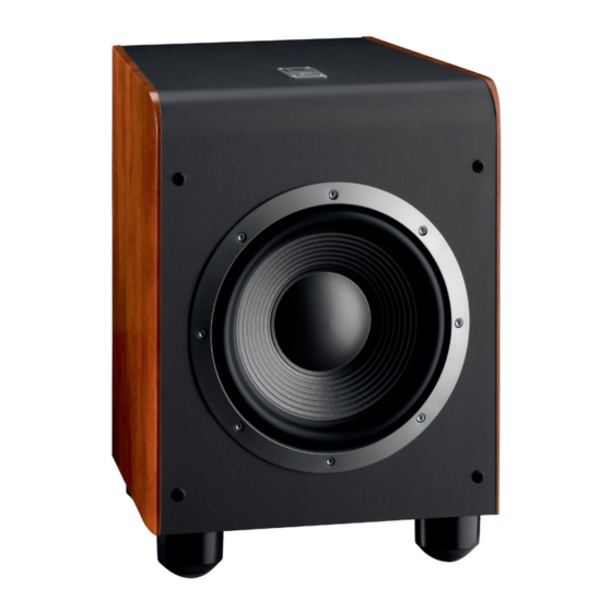
JBL ES150P Service Manual
Es series
Hide thumbs
Also See for ES150P:
- Service manual (30 pages) ,
- Owner's manual (8 pages) ,
- Owner's manual (8 pages)
Summary of Contents for JBL ES150P
- Page 1 ES Series ES150P Powered Subwoofer Service Manual JBL Consumer Products 250 Crossways Park Dr. Woodbury, New York 11797 Rev0 3/2008 Released 2008 Discontinued XXXX...
-
Page 2: Table Of Contents
Weight: 39 lb/17.7kg JBL continually strives to update and improve existing products, as well as create new ones. The specifications and details in this and related JBL publications are therefore subject to change without notice. The Peak Dynamic Power is measured by recording the highest center-to-peak voltage measured across the output of a resistive load equal to... -
Page 3: Detailed Specifications
ES150P JBL ES150P 225W Powered Sub Amp LINE VOLTAGE Yes/No Hi/Lo Line Nom. Unit Notes US 120vac/60Hz 108-132 Vrms Normal Operation EU 230vac/50-60Hz 207-253 Vrms Normal operation, MOMS required QA Test Parameter Specification Unit Limits Conditions Notes Amp Section Type (Class AB, D, other) Min. - Page 4 ES150P QA Test Parameter Specification Unit Limits Conditions Notes Transients/Pops Amplifier activated by signal presence at the 0.5V @ Speaker Output Line input ATO Transient V-peak Turn-on Transient V-peak 0.8V @ Speaker Output AC Line cycled from OFF to ON...
-
Page 5: Packing
ES150P... -
Page 6: Controls/Connections
ES150P CONTROLS AND CONNECTIONS Rear Panel ¡ Phase Switch ™ LFE/Normal Selector £ Subwoofer-Level Control ¢ Crossover Adjustment ∞ Line-Level/LFE Input § Power Switch ¡ ™ £ ¢ ∞ § AC 120V~60Hz... -
Page 7: System Connections
ES150P SYSTEM CONNECTIONS If you have a Dolby ® Digital or DTS ® receiver/processor with a low-frequency-effects (LFE) or subwoofer output: Set LFE/Normal switch to “LFE.” If your receiver/processor does not contain a Dolby Digital or DTS processor, but has subwoofer outputs: Set line-level/LFE switch to “Normal.”... -
Page 8: Operation
In the event that your subwoofer ever needs service, contact your local JBL dealer, or visit www.jbl.com for RED = STANDBY (No signal detected, Amp Off) a service center near you. -
Page 9: Exploded View/Parts List
ES150P... -
Page 10: Test Set-Up And Procedure
ES150P ES150P Test Set Up and Procedure Equipment needed: • Function/signal generator/sweep generator • Integrated Amplifier • Multimeter • Speaker cables General Unit Function (UUT = Unit Under Test) 1) From the signal generator, connect line level (RCA) cables to the Subwoofer Line Level Input jacks L/R on the UUT. -
Page 11: Amplifier Block Diagram
ES150P... - Page 12 ES150P...
-
Page 13: Detailed Troubleshooting
ES150P ES150P Troubleshooting Testing Flow Chart Start Test protection Dc voltage check ±Vcc,±15V Check U ±15Vcc etc Check transformer 168, Test limiter circuit 124, Power on check Check U LED red &green Check vol module Check THD output & connector power, noise cable&... -
Page 14: Drawings
ES150P... - Page 15 ES150P...
- Page 16 ES150P...
- Page 17 ES150P...
- Page 18 ES150P...
-
Page 19: Electrical Parts List
ES150P ES150P (120v) Electrical Parts List Part Number Description Qty Reference Designator INPUT/PREAMP PCB & DAUGHTER BOARD PCB Resistors 110-14392J26-E CARBON RESISTOR 3.9K 1/4W ±5% CF (RoHS) R150, 110-16000j26-e CARBON RESISTOR 0Ω 1/6W ±5% CF (RoHS) R191, 110-16101J26-E CARBON RESISTOR 100Ω 1/6W ±5% CF (RoHS) - Page 20 ES150P Part Number Description Qty Reference Designator INPUT/PREAMP PCB & DAUGHTER BOARD PCB 135-3107m16-e ELECTROLYTIC 100uF 16V ±20% (RoHS) C113,C115,C132,C134,C136, 135-3107m25-e ELECTROLYTIC 100U 25V ±20% (RoHS) C152, 135-3226m50-e ELECTROLYTIC 22U 50V ±20% (RoHS) C151, 139-3227m16-e LOW LEAKAGE EC 220uF 16V ±20% (RoHS)
- Page 21 ES150P Part Number Description Qty Reference Designator MAIN PCB 135-3107m16-e electrolytic cap 100uF 16V ±20% (RoHS) C166,C167, 135-3226m50-e electrolytic cap 22U 50V ±20% (RoHS) C161,C162, 135-3227m10-e electrolytic cap 220U 10V ±20% (RoHS) C156,C157, 139-3227m16-e low leakage ec 220uF 16V±20% (RoHS)
- Page 22 SWITCH ROCK RF-1003-BB210(RoHS) POWER 193-0s4211-e INSULATOR (INSULATION SPACER)42*11 (RoHS) 193-201612tr-e INSULATOR T0-220 16mm*12mm(RoHS) 302-AL-05123-0BAE REAR BOARD300*200*2.5 BLK ES150P/120V USE (RoHS) 306-ABS-05081-0BAE REAR HOUSMG 198*298*102mm WITH 8piece EVA (RoHS) 311-ABS-00028-0BAE KNOB 46077-W P.V.C.(RoHS) LEVEL, CROSSOVER 323-AL-05000-0LAE HEAT SINK (RoHS) 325-FE-00400-0LAE PCBFLOOR STAND 58*9*13.5T (RoHS)
- Page 23 ES150P Part Number Description Qty Reference Designator MISC./MECHANICAL & AC INPUT PCB 351-AM03008A079-E M3*8 MACHINE SCREWCROSS BLK (RoHS) 351-AM03018A905-E MACHINE SCREW M3.0*18 CROSS with nickel (RoHS) 351-HM03006A1258-EMACHINE SCREW M3*6mm CROSS with nickel (RoHS) 351-HM04010A217-E M4*10 MACHINE SCREWCROSS BLK(RoHS) 352-AM03008D040-E ¢3*8 B TYPE PING SCREW CROSS BLK (RoHS) 352-AM03008D041-E ¢3*8 B TYPE PING SCREWCROSS WITH NICKEL (RoHS)
-
Page 24: Ic/Transistor Pinouts
ES150P... -
Page 25: Schematics
ES150P... - Page 26 ES150P...
- Page 27 ES150P...
- Page 28 ES150P...
- Page 29 ES150P...
- Page 30 ES150P...
- Page 31 ES150P...
- Page 32 ES150P...
- Page 33 ES150P...
- Page 34 ES150P...


