Table of Contents
Advertisement
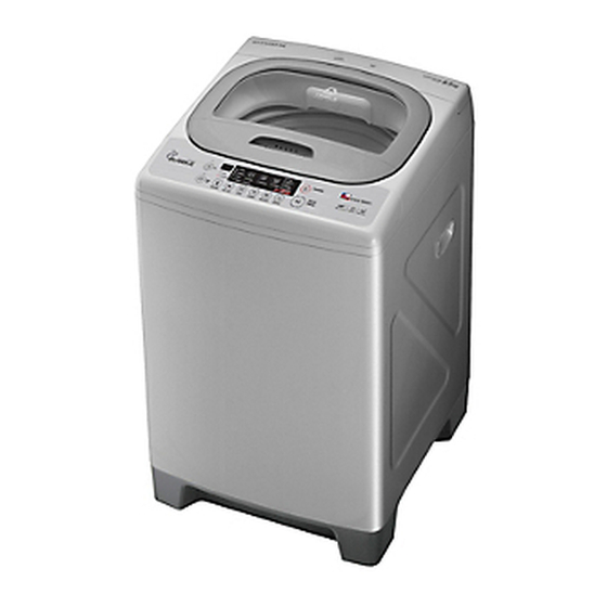
Service Manual
Washing Machine
Model: DWF-900S
✔
Caution
: In this Manual, some parts can be changed for improving, their
performance without notice in the parts list. So, if you need the latest
parts information, please refer to PPL(Parts Price List) in Service
Information Center (http://svc.dwe.co.kr).
DAEWOO ELECTRONICS CORP.
http : //svc.dwe.co.kr
S/M No. :
Aug. 2013
Advertisement
Table of Contents

Related Manuals for Daewoo DWF-900S


Summary of Contents for Daewoo DWF-900S
-
Page 1: Service Manual
S/M No. : Service Manual Washing Machine Model: DWF-900S ✔ Caution : In this Manual, some parts can be changed for improving, their performance without notice in the parts list. So, if you need the latest parts information, please refer to PPL(Parts Price List) in Service Information Center (http://svc.dwe.co.kr). -
Page 2: Table Of Contents
AUTO WASHER AUTO WASHER AUTO WASHER AUTO WASHER AUTO WASHER AUTO WASHER AUTO WASHER AUTO WASHER AUTO WASHER AUTO WASHER AUTO WASHER AUTO WASHER AUTO WASHER AUTO WASHER AUTO WASHER AUTO WASHER AUTO WASHER AUTO WASHER AUTO WASHER AUTO WASHER AUTO WASHER AUTO WASHER AUTO WASHER AUTO WASHER AUTO WASHER AUTO WASHER AUTO WASHER AUTO WASHER AUTO WASHER AUTO WASHER AUTO WASHER AUTO WASHER AUTO WASHER AUTO WASHER AUTO WASHER AUTO WASHER AUTO WASHER AUTO WASHER AUTO WASHER AUTO WASHER AUTO WASHER AUTO WASHER AUTO WASHER AUTO WASHER AUTO WASHER AUTO WASHER AUTO WASHER AUTO WASHER AUTO WASHER AUTO WASHER AUTO WASHER AUTO WASHER AUTO WASHER AUTO WASHER... -
Page 3: Specifications
1. SPECIFICATIONS ITEM DWF-8100 POWER SOURCE AVAILABLE IN ALL LOCAL VOLTAGE POWER 50Hz 320W CONSUMPTION 60Hz 300W(110~127V)/340W(220V) MACHINE 28Kg/28.5Kg(pump) WEIGHT GROSS 31.5Kg/32Kg(pump) DIMENSION(WXHXD) 560 X 948.5 X 570 MATERIAL OF INTERNAL TUB STAINLESS STEEL FULL AUTOMATIC 6 PROGRAMS WASHING PROGRAM ( FUZZY, DELICATE, ECONOMY, BLANKET, BABY CARE, SPORTS WEAR ) WATER LEVEL SELECTOR HIGH(55L), MID(45L), LOW(31L) -
Page 4: Structure Of The Washing Machine
2. STRUCTURE OF THE WASHING MACHINE The parts and features of your washer are illustrated on this page. Become familiar with all parts and features before using your washer. NOTE • The drawing in this book may vary from your washer model. They are designed to show the different features of all models covered by this book, Your model may not include all features. -
Page 5: Functions Of The Control Panel
3. FUNCTIONS OF THE CONTROL PANEL Control panel has micom sensor. As the buttons are pressed, the lamps indicating the selection of your desired washing program will light up. • Press this button to turn the power 'ON' or 'OFF'. •... -
Page 6: Washing Procedure And Program Selection
4. WASHING PROCEDURE AND PROGRAM SELECTION Full Auromatic Program 1. FUZZY PROGRAM ( SENSOR ); • This selection is for general washing except extraordinary clothes. • Artificial brain sensor selects properly the various kind of washing condition such as washing time, rinse times, spin time and water level. - Page 7 4. BLANKET PROGRAM ; • This selection is effective for blanket or duvet. • If you want to soak, press the program button to adjust to " Blanket ". • Procedure to press the button; 1. Press the power 2. Press the program 3.
-
Page 8: Reserved Washing
Reserved Washing 1. FUZZY PROGRAM ( SENSOR ); • Reservation can be made form 2 hours to 48 hours. • To make reservation to complete washing in 8 hours. spin time and water level. Procedure to press the button; Select the program Adjust to water level and water temperature "--"... -
Page 9: Directions For Installation And Use
5. DIRECTIONS FOR INSTALLATION AND USE Location Of Washer Check location where washer will be installed. Make sure you have everything necessary for correct installation. Proper installation is your responsibility. • Do not place or store your washer below 0˚C(32˚F) to avoid any damage from freezing. •... -
Page 10: How To Connect The Inlet Hose
How to Connect the Inlet Hose Be careful not to mistake in supplying between the hot(maximum : 50˚C) and cold water. In using only one water tap or in case of attached one water inlet valve, connect the inlet hose to the cold water inlet valve. -
Page 11: How To Clean The Filter
How To Clean The Filter CLEANING THE LINT FILTER Pull the Filter frame Turn the lint filter Return the filter as it was, and upward. inside out, wash the insert the filter frame into the lint off with water. slot. Lint Filter Filter Frame CLEANING THE WATER INLET FILTER... -
Page 12: Feature And Technical Explanation
6. FEATURE AND TECHNICAL EXPLANATION Feature of the Washing Machine 1 The first air bubble washing system in the world. 2 Quiet washing through the innovational low-noise design. 3 The wash effectiveness is much more enhanced because of the air bubble washing system. 4 The laundry detergent dissolves well in water because of the air bubble washing system. -
Page 13: Automatic Draining Time Adjustment
Automatic Drainning time Adjustment This system adjusts the draining time automatically according to the draining condition. Good draining The washer begins spin process after drainage. Draining Bad draining Draininig time is prolonged. condition No draining Program is stopped and gives the alarm. FUNCTIONAL PRINCIPLE The micom can remember the time from the begining of drain to reset point when the pressure switch reaches to “OFF”... -
Page 14: Softener Dispenser
Softener Dispenser This is the device to dispense the softener automatically by centrifugal force. This is installed inside the auto-balancer. FUNCTIONAL PRINCIPLE 1 Softener stays in room (A) when poured into softener inlet. 2 Softener moves from (A) to (B) by centrifugal force during intermittent spin process. 3 Softener flows from (B) to (C) during rinse process next to intermittent spin. -
Page 15: Automatic Unbalance Adjustment
Automatic Unbalance Adjustment This system is to prevent abnormal vibration during intermittent spin and spin process. FUNCTIONAL PRINCIPLE 1 When the lid is closed, the safety switch contact is “ON” position. 2 In case that wash loads get uneven during spin, the outer tub hits the safety switch due to the serious vibration, and the spin process is interrupted. -
Page 16: Lint Filter
Lint Filter Much lint may be obtained according to the kind of clothes to be washed and some of the lint may also sticks to the clothes. Filter Filter To minimize this possibility a lint filter is provided on the upper part of the tub to filter the wash water as it is Bleach Bleach Inlet... -
Page 17: Gear Mechanism Ass'y
Gear Mechanism Ass’y The proper water currents is made by the rotation of pulsator at a low speed to prevent the damage to the small sized clothes. Pulsator shaft Spin shaft One way clutch bearing Gear unit as Sun gear Planetary gear Internal gear Clutch spring... -
Page 18: Functional Principle Of Bubble Washing Machine
PRINCIPLE OF INTAKE & OUTLET OF THE AIR INTAKE : ARMATURE moves up, and BELLOWS inhales the air. At the same time, protector B is open and A is close. OUTLET : ARMATURE moves down, and BELLOWS exhausts the air. At the same time, protector B is close and A is opend. -
Page 19: Directions For Disassembly And Adjustment
7. DIRECTIONS FOR DISASSEMBLY AND ADJUSTMENT Warning BEFORE ATTEMPTING TO SERVICE OR ADJUST ANY PART OF THE WASHING MACHINE, DISCONNECT THE POWER CORD FROM THE ELECTRIC OUTLET. Gear Mechanism Ass’y Replacement Raise the top plate on the outer cabinet. Loosen the pulsator mounting screw and remove Remove outer tub cover from the tub ass’y. - Page 20 Lay the front of the washer on the floor. Remove four bolts mounting the gear mechanism Remove four bolts mounting the plate-gear protect by ass’y by using a box wrench. using a box wrench and remove plate-gear protect. Remove the V-belt. Pull out the gear mechanism assy.
-
Page 21: Motor Synchronous And Valve Replacement
Motor Synchronous And Valve Replacement(Non Pump Model) Lay the front of the floor. Take out the wire of motor synchonous from the Loosen two special screw and motor synchronous. bracket. Separate the motor sycnchronous from the base. Turn the valve by using screw driver as shown in Remove the valve lid from the valve drain assy. -
Page 22: The Repair Method Of Gear Mechanism For Clutch Spring Problem
8. THE REPAIR METHOD OF GEAR MECHANISM FOR CLUTCH SPRING PROBLEM The structure of gear mechanism Clutch Lever Bearing Clutch Boss Clutch Tip Clutch spring Coupling Pulley Spring Washer Fastening Nut Pulley Shaft Clutch Boss Ass’y Pulley Shaft Fastening Nut Coupling Spring Washer Drum plate... -
Page 23: How To Check The Clutch Spring Problem
how to check the clutch spring Problem PROBLEM 1) THE LAUNDARY IS IN THE SPIN TUB UNEVENLY WHEN JUST STARTING SPIN PROCESS. 2) THEREFORE, IT CAUSE THE SERIOUS NOISE AND VIBRATION WHEN WASHING AND SPINNING PROCESS OR SUPPLING WATER IRREGULARY WHEN SPINNING PROCESS AND CAUSE SHORT OF SPIN PERFORMANCE. -
Page 24: The Process Of Disassemble
The Process Of Disassemble Disassemble 1 Process Notice Use wrench or driver - ratchet handle - extension bar - socket : 10mm Remove the protector Release screws marked 4-point Remove the v-belt Use fixing jig for pulley as to see fig 1. and 17mm-socket for nut Loosen the fastening nut Take out plain washer if it has... - Page 25 Disassemble 2 Process Notice Disassemble the pulley Catch the boss and pull upward with spiral rotate in the clockwise direction Disassemble the clutch boss assembly Separate coupling from clutch boss ass’y Clean the drum plate, coupling surface and contact face between drum plate and coupling It is necessary to keep cotton...
-
Page 26: The Process Of Assemble
The Process Of Assemble Assemble 1 Process Notice Check the uneven face of coupling is assembled upward Assemble the coupling - Push in the clutch boss ass’y with rotating on the clockwise direction. - After assembling, rotate on the clockwise more 2~3 teeth and pull out the pulley shaft upward Assemble the new clutch boss ass’y... - Page 27 Assemble 2 Process Notice - Use fixing jig and 17mm socket wrench as if disassembling, as fastening torque about Assemble the fastening nut 100~200kgf-cm. - Check the end-play, up and downward and check the binding force, too much or not on bi-direct of rotation.
-
Page 28: Trouble Shooting Guide
9. TROUBLE SHOOTING GUIDE NOTES 1. When replace the P.C.B. ASS’Y do not scratch the surface of the P.C.B. ASS’Y. 2. Disconnect the power cord from the electric outlet. Concerning Water Supply PROBLEM CHECK POINT CAUSE SOLUTION Do you open the water Open the water tap. -
Page 29: Concerning Washing
PROBLEM CHECK POINT CAUSE SOLUTION Does the water supply The water inlet valve is Change the water inlet defective. continue while the power valve. is turned off? Does the water supply start The triac of P.C.B is Change the P.C.B as soon as you press the defective. -
Page 30: Concerning Draining
Concerning Draining PROBLEM CHECK POINT CAUSE SOLUTION Install the drain hose Do you install the Improper installation properly. drain hose properly? Is the foreign matter Remove the foreign Malfunction of drainage accumulated inside matter from the pump THE WASHER by the foreign matter the pump housing? housing DOES NOT... -
Page 31: Concerning Spinning
Concerning Spinning PROBLEM CHECK POINT CAUSE SOLUTION Close the lid. Is the lid open? Safety switch is Change the safety Does the safety switch defective. switch. operate normally? Is the connector of Connect the connector Improper connection of P.C.B ASS‘Y connected properly. -
Page 32: Concerning Operation
Concerning Operation PROBLEM CHECK POINT CAUSE SOLUTION Is the plug connect-ed Connect the plug. to electric outlet? Is Fuse opended? Change Fuse INDICATOR LAMPS(L.E.D) Is the condition of DO NOT LIGHT Change P.C.B ASS’Y. Power button is defective power button good? UP WHEN THE POWER BUTTON IS... -
Page 33: Presentation Of The P.c.b Ass'y
10. PRESENTATION OF THE P.C.B ASS'Y Concerning Error Message MESSAGE CAUSE SOLUTION Install drain hose properly. Improper installation of drain hose. Remove foreign matter from drain hose. The drain hose is blocked up by foreign matter. Change drain motor. Drain motor is inferior. Open the water tap. -
Page 34: Appendix
APPENDIX Wiring Diagram [non-pump] WIRING DIAGRAM... - Page 35 [Pump] WIRING DIAGRAM...
-
Page 36: Parts Diagram & Parts List
Parts Diagram OPTION : PANEL B OPTION : DOOR AS PARTS DIAGRAM... - Page 37 Parts List PARTS NAME PARTS CODE DESCRIPTION Q'TY REMARK PLATE T 3614548300 MOLD DECO DOOR B 36116DXJ00 MOLD DOOR B 36117YDV00 MOLD DECO DOOR F 36116DXK00 MOLD DOOR F 36117YDW00 HOOK DOOR 3613102400 8100 MOLD CAP HANDLE 3612615800 GLASS DOOR OUTER 36117YDS00 GLASS DOOR F 36117YDU00...
- Page 38 PARTS NAME PARTS CODE DESCRIPTION Q'TY REMARK Z-AIR_BUBBLE HARNESS AS 3612787922 8A COLD BUBBLE SAINGLE VALVE 3612787926 5A COLD BUBBLE 3612787930 8A COLD/HOT BUBBLE DUAL-VALVE, PUMP 3612787936 5A COLD/HOT BUBBLE 3612787940 8A COLD/HOT NON-BUBBLE 3612787946 5A COLD/HOT NON-BUBBLE 3612787970 8A COLD/HOT BUBBLE DUAL-VALVE 3612787975 5A COLD/HOT BUBBLE...
- Page 39 PARTS DIAGRAM...
- Page 40 Parts List PARTS NAME PARTS CODE DESCRIPTION Q'TY REMARK CABINET 361081WS00 SGCC T=0.57 HANDLE CABINET 3612603310 PLATE UPPER 3614521600 BASE U 3610396300 LEG ADJUST AS 3617702122 DWF-1089W2 LEF FIX 3617703000 HOLDER SUPPORT FL 3615306200 HOLDER SUPPORT FR 3615306400 HOLDER SUPPORT BL 3615306300 HOLDER SUPPORT BR 3615306500...
- Page 41 PARTS DIAGRAM...
- Page 42 Parts List PARTS NAME PARTS CODE DESCRIPTION REMARK BALANCER AS 36161___00 DWF-900S STAINLESS STEEL TUB I 3618832400 SUS 0.4T TUB U 3618832500 HIPS GUIDE FILTER 3612514100 DWF-900S SPECIAL SCREW 3616051629 AUA 5.5X16 PULSATOR AS 37197___00 DWF-900S BALANCER AS 3616104500 DWF-5510PN...
- Page 43 PARTS DIAGRAM...
- Page 44 Parts List PARTS NAME PARTS CODE DESCRIPTION REMARK COVER TUB O 3611434300 TUB O 3618832300 SUSPENSION AS F 36198___00 FRONT SUSPENSION AS B 36198___00 REAR VALVE DRAIN AS 3615408500 DWF-750M NON-PUMP HOSE DRAIN AS 3613227000 LDPE+EVA DWF-752MN HOSE DRAIN AS 3613226900 LDPE+EVA DWF-800WNP PUMP...
-
Page 45: Circuit Diagram
Circuit Diagram CIRCUIT DIAGRAM... - Page 46 DAEWOO ELECTRONICS CORP. 1-2, Jeo-dong 1(il)-ga, Jung-gu, Seoul, Korea C.P.O. BOX 8003 SEOUL, KOREA TELEX: DWELEC K28177-8 CABLE: “DAEWOOELEC” S/M NO. : PRINTED DATE: Aug. 2013...
- Page 47 ABOUT THIS MANUAL ABOUT THIS MANUAL...