Table of Contents
Advertisement
Questions, problems, missing parts?
Amerisun customer service department at 1-800-791-9458 or visit Amerisuninc.com and e-mail
support@amerisuninc.com. For engine related problems, questions and warranty service call the engine
manufacturer 1-877-274-2214.
WARNING! Read and follow all safety rules and instructions in this manual before attempting to operate this
machine. Failure to comply with these instructions may result in personal injury. Save these instructions. This
unit is equipped with an internal combustion engine and may spark resulting in fire or explosion if used near
combustible material or fluid. Only use when the engine's exhaust system is equipped with a spark arrester
meeting applicable local or state laws (if any). The spark arrester shall be maintained in effective working
order by operator.
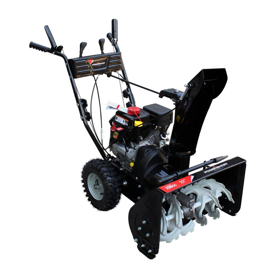
TWO STAGE GAS SNOW THROWER
If you have questions or need technical support, call the
MODEL DB7659A-22 and 24
Advertisement
Table of Contents

Related Manuals for Power smart DB7659A-22


Summary of Contents for Power smart DB7659A-22
- Page 1 TWO STAGE GAS SNOW THROWER MODEL DB7659A-22 and 24 Questions, problems, missing parts? If you have questions or need technical support, call the Amerisun customer service department at 1-800-791-9458 or visit Amerisuninc.com and e-mail support@amerisuninc.com. For engine related problems, questions and warranty service call the engine manufacturer 1-877-274-2214.
-
Page 2: Table Of Contents
TABLE OF CONTENTS Safety............................... 2 Feature Identification ..........................6 Box Contents ............................7 Assembly ..............................7 Operation ..............................10 Operating Your Snow Thrower ....................... 12 Maintenance ............................13 Troubleshooting ............................22 Warranty ..............................24 DISCLAIMER The information contained within this manual is the latest information as of the publication date. All content and images are subject to change without notice. -
Page 3: Safety
SAFETY Preparation Thoroughly inspect the area where the This symbol points out important safety equipment is to be used. Remove all doormats, instructions which, if not followed, could newspapers, sleds, boards, wires and other endanger the personal safety and or foreign object, which could be tripped over or property of yourself and others. - Page 4 • Exercise caution to avoid slipping or falling, • Never fill containers inside a vehicle or on a truck or especially when operating in reverse. trailer bed with a plastic liner. Always place • Stay alert, watch what you are doing and use containers on the ground away from your vehicle common sense when operating your Snow Thrower.
- Page 5 • If the machine should start to vibrate abnormally, • Maintain or replace safety and instruction labels, as stop the engine, disconnect the spark plug wire and necessary. ground it against the engine.Inspect thoroughly for • Observe proper disposal laws and regulations for damage.
-
Page 6: Safety Symbols
Safety Symbols This page depicts and describes safety symbols that may appear on this product. Read, understand and follow all instructions on the machine before attempting to assemble and operate. -
Page 7: Feature Identification
FEATURE IDENTIFICATION TECHNICAL SPECIFICATIONS Clearing Width: DB7659A 22 and 24 inches Clearing Height: 16 inches 4 Forward and 2 Reverse Speeds Engine Displacement: 208cc, 4 stroke A - Drive Control Handle E - Engine I - Snow/Ice Clean Out Tool B - Speed Control Lever F - Skid Shoe J - Chute Assembly... -
Page 8: Box Contents
A. Drive Control Handle K. Chute Deflector Lever Located on the right side of the upper handle, the The angle of the chute deflector controls the Drive Control is used to engage and disengage discharge distance of the snow. Raising the the drive wheels. -
Page 9: Handle Assembly
NOTICE: Make sure all fasteners are tightened 2. Attach the chute rotation bar to the mount before starting the machine. bracket onto the chute housing using two hex screws, washers and locknuts. Tighten Handle Assembly fasteners securely. 1. Attach the lower handles using four (4) bolts. Each side will require two (2) bolts. - Page 10 NOTICE: Do not bend or kink the control cables. The cables should be routed under the handle assembly and not wrapped around the handle or knobs. The cables must move freely and not bind. 3. Secure the speed control cables to the handle with provided clips.
-
Page 11: Operation
4. Place a spacer board on the ground WARNING! DO NOT USE YOUR HANDS TO underneath the auger shave plate between UNCLOG CHUTE. Stop the motor before the skid shoes. The thickness of the board removing debris. Use the supplied clean out should be the same as the height above the tool to unclog the chute. - Page 12 Auger and Drive Controls Drive Speed Control Lever 1. To engage the auger, press down on the Move the drive speed control lever to the desired auger control handle (left side handle). speed. There are six (6) settings: four (4) forward speeds and two (2) reverse speeds.
-
Page 13: Chute Discharge Angle Adjustment
Chute Discharge Angle Adjustment Clearing Snow WARNING! Always disengage the drive and Start the engine (see ENGINE manual) once your auger control handles before making Snow Thrower has been running outside for adjustments. Make sure the augers are several minutes, it is now ready for use. Make stopped and the machine is not moving. -
Page 14: Maintenance
Stopping After each snow removal session, run the Snow Thrower for a few minutes to prevent the When finished using your Snow Thrower, collector/impeller from freezing. Stop the engine, perform the following steps to shut it down. wait for all revolving parts to stop completely, and 1. -
Page 15: Auger Or Impeller Jams
Auger Shear Pin Replacement Shear pins are used to attach the auger shaft to Auger or Impeller Jams the auger blades. A clog or jam in the augers may cause one or multiple shear pins to break. WARNING! The auger and impeller rotate at The shear pins are a safety mechanism and fast speeds which can cause harm or even designed to break under high load or impact to... - Page 16 Drive Control Cable Tension 2 – Adjustment Plate Adjustment 3 – Lower Drive Control Cable 4 – Slip Cover WARNING! Entanglement Hazard - Before 5 – Adjustment Plate Lower Cable Opening performing any adjustment procedures, make 4. Adjustment is made by changing the position sure the engine is off and remove the spark of the lower cable in the adjustment plate plug wire from the spark plug to ensure the...
- Page 17 Depending on if the cable setting is biased plug wire from the spark plug to ensure the towards forward or reverse, adjustment of the engine cannot accidently start. Never adjust cables will vary. belt tension with the engine running. To adjust the cables one cable should be moved Note: During operation the augers turn at a up and the other down equally in their respective slower speed than the impeller, this is normal.
-
Page 18: Auger Belt Removal
in-line with the cable below the control handle and is covered by a black plastic slip cover. The adjustment plate is used to adjust auger belt tension. 4. Adjustment is made by changing the position of the lower cable in the adjustment plate holes (1 to 9). - Page 19 5. Right Side - Remove the hex screw, lock washers and flat washers attaching the auger 2. Remove 2 hex head screws and remove belt housing to the main frame. cover. 6. Remove the belt from the drive pulley while pulling the right side of the auger housing away from the main frame just enough to 3.
-
Page 20: Auger Belt Installation
Auger Belt Installation WARNING! Entanglement Hazard - Before performing any service procedures, make sure the engine is off and remove the spark plug wire from the spark plug to ensure the engine cannot accidently start. NOTICE: Before installing the auger belt, see Auger Belt and Related Component Inspection and repair or replace any components as required. -
Page 21: Auger Belt And Related Component Inspection
4. Install and/or tighten the hex screws attaching the auger housing to the main frame. Tighten all fasteners securely, do not over tighten. 5. With the belt installed on both pulleys and tension pulley in position, move the belt guide pin to within 3/16 to 3/8 in. -
Page 22: Cleaning
Storage • Broken sheave or hub • Loose or missing mounting bolts WARNING! Never store your Snow Thrower • Bent or "out-of-round" condition (pulley not spin true for extended periods of time with fuel in the on shaft) tank. Fuel stabilizer can be added to the fuel to •... -
Page 23: Troubleshooting
TROUBLESHOOTING Problem Possible Causes Remedy WARNING - Before attempting to make any inspections, repairs or adjustments, stop the engine, wait for all moving parts to stop moving and carefully disconnect the engine spark plug wire. If tipping or turning the snow blower is required for any inspection or repair, first wait until the engine is cool to the touch and then drain the engine of all fuel and oil into suitable containers and store or dispose of in a proper manner. - Page 24 Drive System 1 Drive control cable loose, broken or binding 1 Repair or adjust drive control cable and adjust tension, see Auger and Drive Cable Adjustment 2 Drive belt loose or damaged 2 Check drive belt tension pulley for damage or incorrect tension, repair as necessary. Replace drive belt. No forward or reverse 3 Friction drive wheel is worn or damaged 3 Replace friction drive wheel...
-
Page 25: Warranty
WARRANTY ONE YEAR WARRANTY ENGINE WARRANTY See the ENGINE manual included with this snow thrower for engine warranty information. For all engine related warranty issues contact LCT engine corporation - phone 1-877-274-2214. WARRANTY For one year from date of retail purchase within U.S.A., the manufacturer will, at its option, repair or replace, for the original purchaser, free of charge, any part or parts found to be defective in material or workmanship.