Table of Contents
Advertisement
PRECAUTIONS TO BE OBSERVED BEFORE AND
DURING SERVICING TO AVOID EXPOSURE TO
EXCESSIVE MICROWAVE ENERGY
BEFORE SERVICING
CHAPTER 1. WARNING TO SERVICE PERSONNEL
CHAPTER 2. MICROWAVE MEASUREMENT PRO-
CEDURE
CHAPTER 3. FOREWORD AND WARNING
CHAPTER 4. PRODUCT DESCRIPTION
CHAPTER 5. GENERAL INFORMATION
CHAPTER 6. OPERATION
SHARP CORPORATION
SERVICE MANUAL
MICROEAVE OVEN
MODELS
In the interest of user-safety the oven should be restored to its
original condition and only parts identical to those specified
should be used.
WARNING TO SERVICE PERSONNEL: Microwave ovens
contain circuitry capable of producing very high voltage
and current, contact with following parts may result in a se-
vere, possibly fatal, electrical shock. (High Voltage Capac-
itor, High Voltage Power Transformer, Magnetron, High
Voltage Rectifier Assembly, High Voltage Harness etc..)
CONTENTS
CHAPTER 7. TROUBLESHOOTING GUIDE
CHAPTER 8. TEST PROCEDURES
CHAPTER 9. TOUCH CONTROL PANEL ASSEM-
BLY
CHAPTER 10. PRECAUTIONS FOR USING LEAD-
FREE SOLDER
CHAPTER 11. COMPONENT REPLACEMENT AND
ADJUSTMENT PROCEDURE
CHAPTER 12. CIRCUIT DIAGRAMS
Parts Guide
No. S2501R230KPKW
R-230KK
R-230KW
This document has been published to be used
for after sales service only.
The contents are subject to change without notice.
R-230KK
R-230KW
Advertisement
Table of Contents

Related Manuals for Sharp R-230KK


Summary of Contents for Sharp R-230KK
- Page 1 R-230KK R-230KW SERVICE MANUAL No. S2501R230KPKW MICROEAVE OVEN R-230KK MODELS R-230KW In the interest of user-safety the oven should be restored to its original condition and only parts identical to those specified should be used. WARNING TO SERVICE PERSONNEL: Microwave ovens...
-
Page 2: Table Of Contents
CONTENTS PRECAUTIONS TO BE OBSERVED BEFORE [13] K : KEY UNIT TEST........8-5 AND DURING SERVICING TO AVOID EXPOSURE [14] L : RELAY TEST ......... 8-6 TO EXCESSIVE MICROWAVE ENERGY [15] M : DEFROST TEST........8-6 [16] N : FOIL PATTERN ON THE PRINTED BEFORE SERVICING WIRING BOARD TEST...... -
Page 3: Precautions To Be Observed Before
Before servicing an operative unit, perform a microwave emission check as per the Microwave Measurement Procedure outlined in this service manual. If microwave emissions level is in excess of the specified limit, contact SHARP ELECTRONICS CORPORATION immediately @1-800-237-4277. If the unit operates with the door open, service person should 1) tell the user not to operate the oven and 2) contact SHARP ELECTRONICS CORPORATION and Food and Drug Administration's Center for Devices and Radiological Health immediately. -
Page 4: Before Servicing
R230KW R230KW CHAPTER 1. WARNING TO SERVICE PERSONNEL Service Manual Microwave ovens contain circuitry capable of producing very high voltage and current, contact with following parts may result in a severe, possibly fatal, electrical shock. (Example) High Voltage Capacitor, High Voltage Power Transformer, Magnetron, High Voltage Rectifier Assembly, High Voltage Harness etc.. Read the Service Manual carefully and follow all instructions. -
Page 5: Chapter 2. Microwave Measurement Procedure Requirements
R230KW R230KW CHAPTER 2. MICROWAVE MEASUREMENT PROCEDURE Service Manual [1] Requirements: 1. Microwave leakage limit (Power density limit): The power density of microwave radiation emitted by a microwave oven should not exceed 1mW/ at any point 5cm or more from the external surface of the oven, measured prior to acquisition by a purchaser, and thereafter (through the use- ful life of the oven), 5 mW/cm at any point 5cm or more from the external surface of the oven. -
Page 6: Chapter 3. Foreword And Warning Foreword
Service Manual [1] FOREWORD This Manual has been prepared to provide Sharp Electronics Corp. Service Personnel with Operation and Service Information for the SHARP MICROWAVE OVENS, R-230KK and R-230KW. It is recommended that service personnel carefully study the entire text of this manual so that they will be qualified to render satisfactory customer service. -
Page 7: Chapter 4. Product Description
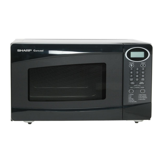
R230KW R230KW CHAPTER 4. PRODUCT DESCRIPTION Service Manual [1] SPECIFICATIONS ITEM DESCRIPTION 120 Volts Power Requirements 60 Hertz Single phase, 3 wire grounded Power Consumption 1170W / Approx. 10 Amperes 800 W nominal of RF microwave energy (IEC Test procedure) Power Output Operating frequency 2450 MHz Width 18-1/8"... -
Page 8: Chapter 5. General Information Grounding Instructions
R230KW R230KW CHAPTER 5. GENERAL INFORMATION Service Manual [1] GROUNDING INSTRUCTIONS This oven is equipped with a three prong grounding plug. It must be plugged into a wall receptacle that is properly installed and grounded in accor- dance with the National Electrical Code and local codes and ordinances. In the event of an electrical short circuit, grounding reduces the risk of electric shock by providing an escape wire for the electric current. - Page 9 R230KW 2. TOUCH CONTROL PANEL NOTE: Some one-touch cooking features such as "MINUTE PLUS" are disabled after three minutes when the oven is not in use. These features are automatically enabled when the door is opened and closed or the STOP/ CLEAR pad is pressed. 5 –...
-
Page 10: Chapter 6. Operation
R230KW R230KW CHAPTER 6. OPERATION Service Manual [1] DESCRIPTION OF OPERATING SEQUENCE The following is a description of component functions during oven operation. 1. OFF CONDITION 3. POWER LEVEL COOKING Closing the door activates door sensing switch and secondary inter- When Variable Cooking Power is programmed, the 120 volts A.C. -
Page 11: Oven Schenatic
R230KW [2] OVEN SCHENATIC 1. Off Condition SCHEMATIC NOTE: CONDITION OF OVEN 1. DOOR CLOSED 2. CLOCK APPEARS ON DISPLAY THERMAL CUT-OUT (OVEN) NOTE: " " indicates components with potentials above 250V TEMPERATURE FUSE (OVEN) FUSE N.O. POWER TRANSFORMER COM. (RY-2) (RY-1) PRIMARY... -
Page 12: Description And Function Of Components
R230KW [3] DESCRIPTION AND FUNCTION OF COMPONENTS 1. DOOR OPEN MECHANISM 4. TURNTABLE MOTOR The door is opened by pushing the open button on the control panel, The turntable motor rotates the turntable located on the bottom of the refer to the Figure D-1. oven cavity, so that the food on the turntable is cooked evenly. -
Page 13: Chapter 7. Troubleshooting Guide
R230KW R230KW CHAPTER 7. TROUBLESHOOTING GUIDE Service Manual Never touch any part in the circuit with your hand or an uninsulated tool while the power supply is connected. When troubleshooting the microwave oven, it is helpful to follow the Sequence of Operation in performing the checks. Many of the possible causes of trouble will require that a specific test be performed. -
Page 14: Chapter 8. Test Procedures
R230KW R230KW CHAPTER 8. TEST PROCEDURES Service Manual [1] Procedure A : MAGNETRON ASSEMBLY TEST 1. Disconnect the power supply cord, and then remove outer case. 2. Open the door and block it open. 3. Discharge high voltage capacitor. 4. To test for an open filament, isolate the magnetron from the high voltage circuit. A continuity check across the magnetron filament leads should indicate less than 1 ohm. -
Page 15: D : High Voltage Capacitor Test
R230KW 6. Reinstall the outer case (cabinet). 7. Reconnect the power supply cord after the outer case is installed. 8. Run the oven and check all functions. NOTE: Be sure to use an ohmmeter that will supply a forward bias voltage of more than 6.3 volts. [4] Procedure D : HIGH VOLTAGE CAPACITOR TEST 1. -
Page 16: F : Primary Interlock System Test
R230KW 5. Reconnect all leads removed from components during testing. 6. Reinstall the outer case (cabinet). 7. Reconnect the power supply cord after the outer case is installed. 8. Run the oven and check all functions. [8] Procedure F : PRIMARY INTERLOCK SYSTEM TEST 1. -
Page 17: H : Blown Minitor Fuse Test
R230KW [10] Procedure H : BLOWN MINITOR FUSE TEST 1. Disconnect the power supply cord, and then remove outer case. 2. Open the door and block it open. 3. Discharge high voltage capacitor. 4. If the monitor fuse is blown when the door is opened, check the primary interlock relay, secondary interlock switch and monitor switch according to the "TEST PROCEDURE"... - Page 18 R230KW c) When touching the pads, sometimes a pad produces no signal. If the key unit is defective. 1) Disconnect the power supply cord and then remove outer case. 2) Open the door and block it open. 3) Discharge high voltage capacitor. 4) Replace the key unit.
-
Page 19: L : Relay Test
R230KW Pin NO. G1 Pin NO. G10 WARM REHEAT DEFROST POWER Key unit ribbon POPCORN LEVEL cable STOP TIMER COOK CLOCK CLEAR START SOFTEN MELT MINUTE PLUS Key unit (Membrane Switch) front view [14] Procedure L : RELAY TEST 1. Disconnect the power supply cord, and then remove outer case. 2. - Page 20 R230KW 4) Follow the troubleshooting guide given below for repair. STEPS OCCURRENCE CAUSE OR CORRECTION Only pattern at “a” is broken. *Insert jumper wire J1 and solder. Pattern at “a” and “b” are broken. *Insert the coil RCILF2003YAZZ between “c” and “d”. 5) Make a visual inspection of the varistor.
-
Page 21: Chapter 9. Touch Control Panel Assem
R230KW R230KW CHAPTER 9. TOUCH CONTROL PANEL ASSEMBLY Service Manual [1] OUTLINE OF TOUCH CONTROL PANEL This circuit consists of 4-digits, 12-segments and 3-common elec- trodes using a Liquid Crystal Display. The touch control section consists of the following units as shown in 3) Power Source Circuit the touch control panel circuit. - Page 22 R230KW Pin No. Signal Description COM2 OUT Common data signal. Connected to LCD signal COM2. COM3 OUT Terminal not used. 26-37 SEG0-SEG11 OUT Segment data signal. Connected to LCD.The relation between signals are as follows: LSI signal (Pin No.) LCD (segment) LSI signal (Pin No.) LCD (segment) SEG 0 (26) ----------------- SEG 1...
-
Page 23: Servicing For Touch Control Panel
R230KW Pin No. Signal Description Terminal not used. Terminal not used. BZO90 Signal to sound buzzer (2.0 kHz). A: key touch sound. B: Completion sound. 0.1 sec. H : GND L : -5V 2.0 sec. H : GND L : -5V Terminal not used. -
Page 24: Chapter 10. Precautions For Using Lead- Free Solder
R230KW R230KW CHAPTER 10. PRECAUTIONS FOR USING LEAD-FREE SOLDER Service Manual [1] Employing lead-free solder The "Main PWB" of this model employs lead-free solder. This is indicated by the "LF" symbol printed on the PWB and in the service manual. The suf- fix letter indicates the alloy type of the solder. -
Page 25: Chapter 11. Component Replacement
1. Door does not close firmly. 4. If the outer case (cabinet) is not fitted. WARNING FOR WIRING To prevent an electric shock, take the following precau- 3) Sharp edge: tions. Bottom plate, Oven cavity, Waveguide flange and 1. Before wiring, other metallic plate. -
Page 26: Outer Case Removal
R230KW [2] OUTER CASE REMOVAL To remove the outer case, procedure as follows. 1. Disconnect the power supply cord. 2. Open the oven door and block it open. 3. Remove the two (2) screws from the lower portion of the rear cab- inet using a T20H Torx type or GTXH20-100 screw driver. -
Page 27: Positive Lockr Connector (No- Case Type) Removal
R230KW [6] POSITIVE LOCK CONNECTOR (NO-CASE TYPE) REMOVAL Terminal 1. Disconnect the power supply cord, and remove outer case. Positive lock¨ connector 2. Open the door and block it open. 3. Discharge high voltage capacitor. Push 4. Push the lever of positive lock connector. Lever 5. -
Page 28: Power Supply Cord Replacement
5. Re-install the turntable motor cover to the bottom plate with one (1) 4. Where the corners have been snipped off bend corner areas flat. screw. No sharp edges must be evident after removal of the turntable motor cover. TTM packing 5. -
Page 29: Door Sensing Switch/Secondary Interlock Switch And Monitor Switch Removal
R230KW 8. Remove the fan blade assembly from the shaft of the fan motor by 3. Apply the screw lock tight into the hole (for shaft) of the fan blade. pulling and rotating the fan blade with your hand. 4. Install the fan blade to the shaft of fan motor by pushing the fan 9. -
Page 30: Door Replacement
R230KW 2. After adjustment, check the following. 1. In and out play of door remains less than 0.5mm when in the latched position. First check upper position of latch hook, pushing and pulling upper portion of door toward the oven face. Then check Latch Hook Door lower portion of the latch hook, pushing and pulling lower portion of... - Page 31 R230KW 4. SEALER FILM 1. Put the adhesive tape on the backing film of the sealer film as shown in Fig. C-8 2. Tear the backing film by pulling the adhesive tape. Upper Oven Upper Hinge 3. Put the pasted side of the sealer film on the door panel Oven Hinge Sealer film Backing film...
-
Page 32: Chapter 12. Circuit Diagrams
R230KW R230KW CHAPTER 12. CIRCUIT DIAGRAMS Service Manual [1] Pictorial Diagram (Figure S-1) R Y 1 (RED) WHT RED Figure S-1. Pictorial Diagram 12 – 1... -
Page 33: Control Panel Circuit (Figure S-2)
R230KW [2] Control Panel Circuit (Figure S-2) Figure S-2. Control Panel Circuit 12 – 2... -
Page 34: Printed Wiring Board (Figure S-3)
R230KW [3] Printed Wiring Board (Figure S-3) Figure S-3. Printed Wiring Board 12 – 3... -
Page 35: Parts List
INDEX TOP PAD ASSEMBLY FPADBA585WRKZ POLYETHYLENG BAG SSAKHA014WRE0 DOOR PROTECTION SHEET CABINET COVER for R-230KW SPADPA580WRE0 SPADFA449WRE0 PLASTIC SHEET for R-230KK 6-5 INSTRUCTION BOOK SPADPA615WREZ MICROWAVE OVEN 6-1 TURNTABLE TRAY BOTTOM PAD ASSEMBLY FPADBA586WRKZ FOAM SHEET for R-230KK SPAKHA014WREZ INTO THE... - Page 36 R230KW [1] OVEN PARTS 1-10 4-11 1-12 4-14 4-12 4-10 4-13 1-11...
- Page 37 Special screw (Torx tamper pfoof screw) LX-CZ0052WRE0 Special screw LX-EZA042WRE0 Special screw LX-CZA073WRE0 Special screw XHPSD40P08000 Screw : 4mm x 8mm XOTSD40P08000 Screw : 4mm x 8mm XOTSE40P08000 Screw : 4mm x 8mm [R-230KW] XOTSF40P08000 Screw : 4mm x 8mm [R-230KK]...
- Page 38 R230KW [2] DOOR AND CONTROL PANEL PARTS 3-1-2 3-1-1...
- Page 39 PARTS CODE DESCRIPTION RANK MARK RANK [2] DOOR AND CONTROL PANEL PARTS FPNLCB845WRKZ Control panel frame with key unit [R-230KW] FPNLCB846WRKZ Control panel frame with key unit [R-230KK] 3-1-1 PSHEPB087WREZ Graphic sheet [R-230KW] 3-1-1 PSHEPB089WREZ Graphic sheet [R-230KK] 3-1-2 QSW-KA053DRZZ...
- Page 40 1-4-3 NTNT-A034WRF0 1-6-1 [ P ] PCOVPA419WREZ 1-4-8 PCUSGA615WREZ 1-4-14 PCUSGA661WREZ 1-4-13 PCUSGA662WREZ 1-4-12 COPYRIGHT © 2005 BY SHARP CORPORATION PCUSUA501WRP0 1-4-11 PCUSUA633WREZ 2-3-8 ALL RIGHTS RESERVED. PDUC-A908WRWZ 1-4-4 PDUC-A909WRPZ 1-4-9 PHOK-A144WRFZ 1-4-1 No part of this publication may be reproduced, stor-...