Icom IC-208H Instruction Manual
Vhf/uhf fm transceiver
Hide thumbs
Also See for IC-208H:
- Service manual (52 pages) ,
- Service manual (8 pages) ,
- Adjustment procedure (12 pages)
Table of Contents
Advertisement
Quick Links
INSTRUCTION MANUAL
VHF/UHF FM TRANSCEIVER
i208H
This device complies with Part 15 of the FCC rules. Operation is sub-
ject to the following two conditions: (1) This device may not cause
harmful interference, and (2) this device must accept any interference
received, including interference that may cause undesired operation.
Advertisement
Table of Contents

Related Manuals for Icom IC-208H


Summary of Contents for Icom IC-208H
- Page 1 INSTRUCTION MANUAL VHF/UHF FM TRANSCEIVER i208H This device complies with Part 15 of the FCC rules. Operation is sub- ject to the following two conditions: (1) This device may not cause harmful interference, and (2) this device must accept any interference received, including interference that may cause undesired operation.
- Page 2 We want to take a couple of moments of your time to thank you for making your IC-208H your radio of choice, and hope you agree with Icom’s philosophy of “technology first.” Many hours of research and development went into the design of your IC-208H.
-
Page 3: Precaution
For U.S.A. only CAUTION: Changes or modifications to this device, not ex- pressly approved by Icom Inc., could void your authority to operate this device under FCC regulations. -
Page 4: Table Of Contents
SUPPLIED ACCESSORIES q DC power cable (3 m) ………………………………………1 w Mobile mounting bracket …………………………………1 e Microphone (HM-133)* ……………………………………1 r Fuse (20 A) …………………………………………………1 t Mounting screws, nuts and washers …………………1 set y Microphone hanger …………………………………………1 u Separation cable † (3.5 m; 11.5 ft) …………………………1 *HM-118N or HM-118TN/TAN HAND MICROPHONE... - Page 5 I One-touch PTT function ... 18 I Audio mute function ... 18 4 REPEATER OPERATION ... 19–25 I General ... 19 I Accessing a repeater ... 20 I Subaudible tones ... 22 I Offset frequency ... 24 I Auto repeater (USA version only) ... 25 5 MEMORY OPERATION ...
-
Page 6: Quick Reference Guide
QUICK REFERENCE GUIDE I Installation D Installation methods • Single body installation Transceiver • The supplied mounting bracket (or optional MB-17A) can be used for the main unit installation. • Remote installation Front panel Main unit • The supplied OPC-600/R SEPARATION CABLE remote installation. - Page 7 D Location Select a location which can support the weight of the trans- ceiver and does not interfere with driving. We recommend the locations shown in the diagram below. NEVER place the transceiver or remote controller where nor- mal operation of the vehicle may be hindered or where it could cause bodily injury.
- Page 8 QUICK REFERENCE GUIDE D Microphone connection Connect the supplied microphone as illustrated below. D Separation cable connection Using the supplied separation cable (3.5 m; 11.5 ft) or the op- tional separation cable (7 m; 23 ft) the controller can be sep- arated from the main unit, doubling as a remote controller.
- Page 9 Velcro pads (small) or rubber pad to the bracket as shown below; then attach the remote con- ″) ⁄ troller. MB-58 • When using the optional MB-65 Mounting bolt Adjust the viewing angle for maximum visibility function display. QUICK REFERENCE GUIDE IC-208H remote controller MB-58 MB-65...
- Page 10 DO NOT use the cigarette lighter socket for power con- nections. (See p. 5 for details) Attach a rubber grommet when passing the DC power cable through a metal plate to prevent a short circuit. • CONNECTING TO A DC POWER SOURCE IC-208H ⊕ − black Fuses...
-
Page 11: Antenna Installation
D Antenna installation • Antenna location To obtain maximum performance from the transceiver, select a high-quality antenna and mount it in a good location. A non- radial antenna should be used when using a magnetic mount. Roof-mount antenna (Drill a hole or use a magnetic mount.) Gutter-mount antenna To antenna •... -
Page 12: I Your First Contact
QUICK REFERENCE GUIDE I Your first contact Now that you have your IC-208H installed in your car or shack, you are probably excited to get on the air. We would like to take you through a few basic operation steps to make your first “On The Air”... - Page 13 3. Tune the frequency The tuning dial will allow you to dial in the frequency you want to operate. Pages 12 and 13 will instruct you on how to set the tuning speed. [DIAL] Rotate [DIAL] to tune the frequency. Using the HM-133 You can directly enter the frequency with the HM-133 keypad for the main band.
-
Page 14: I Repeater Operation
QUICK REFERENCE GUIDE I Repeater operation 1. Setting duplex Push [BAND] to select the frequency band. Push [LOW•DUP] for 1 sec. once or twice to select minus du- plex or plus duplex. • The USA version has an auto repeater function, therefore, setting duplex is not required. -
Page 15: I Programming Memory Channels
I Programming memory channels The IC-208H has a total of 512 memory channels (including 10 scan edges and 2 call channels) for storing often used op- erating frequency, repeater settings, etc. 1. Setting a frequency In VFO mode, set the desired operating frequency with re- peater, tone and tuning steps, etc. -
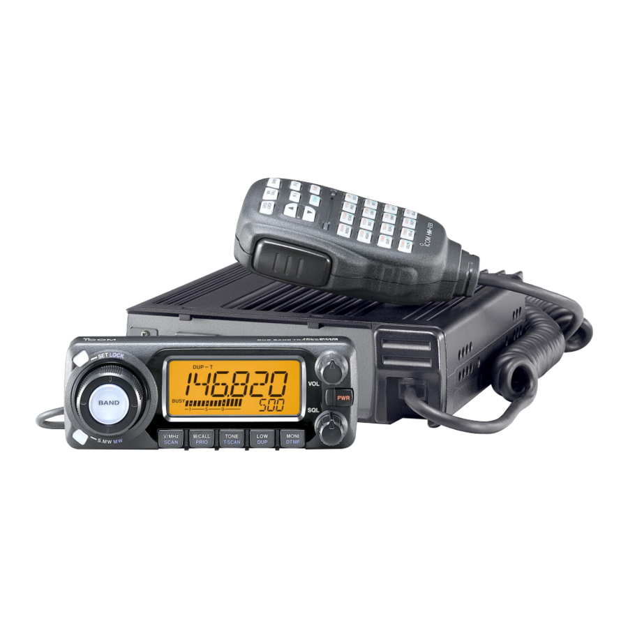
Page 16: Panel Description
PANEL DESCRIPTION I Front panel— controller q SET•LOCK SWITCH [SET•LOCK] ➥ Enters set mode when pushed. (p. 56) ➥ Switches the lock function ON and OFF when pushed for 1 sec. (p. 14) w TUNING DIAL [DIAL] Selects the operating frequency (p. 12), memory channel (p. - Page 17 y SQUELCH CONTROL [SQL] Varies the squelch level. (p. 15) • The RF attenuator activates and increases the attenuation when rotated clockwise to the center position and further. (p. 16) u MONITOR•DTMF SWITCH [MONI•DTMF] ➥ Push to switch the monitor function ON and OFF. (p. 15) ➥...
-
Page 18: I Function Display
PANEL DESCRIPTION I Function display q TRANSMIT INDICATOR ➥ Appears while transmitting. (p. 17) ➥ Blinks while transmitting with the one-touch PTT func- tion. (p. 18) w DUPLEX INDICATORS (p. 20) “DUP” appears when plus duplex, “DUP –” appears when minus duplex (repeater) operation is selected. - Page 19 r NARROW MODE INDICATOR (p. 65) Appears when the FM/AM narrow mode is selected. Narrow mode is available with USA version only. t AM INDICATOR (p. 65) Appears when AM mode is selected. y SQUELCH ATTENUATOR INDICATOR (p. 16) Appears when the squelch attenuator function is activated. •...
-
Page 20: I Rear Panel
PANEL DESCRIPTION I Rear Panel q DATA SOCKET [DATA] Connects a TNC (Terminal Node Controller), etc. for data communications. • See p. 6 for connection information. w EXTERNAL SPEAKER JACK [SP] Connects an 8 Ω speaker. • Audio output power is more than 2.0 W. e COOLING FAN Rotates while transmitting. - Page 21 D DATA JACK PIN ASSIGNMENT q DATA IN Input terminal for data transmit. See p. 63 for details on how to toggle data speed between 1200 (AFSK) and 9600 bps (G3RUH, GMSK). w GND Common ground for DATA IN, DATA OUT and AF OUT. e PTT P PTT terminal for packet operation only.
-
Page 22: I Microphone (Hm-133)
PANEL DESCRIPTION I Microphone (HM-133*) *A different microphone may be supplied de- pending on version. q VFO/LOCK SWITCH [VFO/LOCK] ➥ Push to select VFO mode. (p. 11) ➥ Push for 1 sec. to switch the lock function ON and OFF. (p. -
Page 23: I Microphone Keypad
I Microphone keypad FUNCTION Switches between opening and closing the squelch. Starts and stops scanning. Starts and stops priority watch. Selects high output power. Selects mid. output power. Selects low output power Selects minus duplex operation. Selects plus duplex operation. Selects simplex operation. - Page 24 PANEL DESCRIPTION FUNCTION ➥ Cancels frequency entry. ➥ Cancels the scan or priority watch. ➥ Exit set mode. ➥ Enters set mode ➥ Advances the set mode selection order after entering set mode. ➥ Sets the keypad for numeral input. ➥...
-
Page 25: I Optional Microphones (Hm-118N/Tn/Tan)
I Optional Microphones (HM-118N/TN/TAN) • HM-118N • HM-118TN/TAN (DTMF) q PTT SWITCH Push and hold to transmit; release to receive. w UP/DOWN SWITCHES [UP]/[DN] ➥ Push either switch to change operating frequency, memory channel, set mode setting, etc. (pgs. 12, 26, 56) ➥... -
Page 26: Setting A Frequency
➥ Push [PWR] for 1 sec. to turn power ON and OFF. D Operating frequency band selection The IC-208H has 2 m and 70 cm bands for transmission and reception. In addition, extra frequency bands 127, 220, 350, 500 and 900 MHz bands are available for wide-band receiver capability (except Taiwan and Korean version). -
Page 27: I Using The Tuning Dial
I Using the tuning dial q Rotate [DIAL] to set the frequency. • If VFO mode is not selected, push [V/MHz•SCAN] to select VFO mode. • The frequency changes in the selected tuning steps. (p. 13) [DIAL] [V/MHz•SCAN] wTo change the frequency in 1 MHz (10 MHz for some versions) steps, push [V/MHz•SCAN], then rotate [DIAL]. -
Page 28: I Tuning Step Selection
SETTING A FREQUENCY I Tuning step selection Tuning steps are the minimum frequency change increments when you rotate [DIAL] or push [Y]/[Z] on the microphone. Independent tuning step for each frequency bands can be set for individual tuning convenience. The following tuning steps are available. -
Page 29: I Lock Functions
I Lock functions To prevent accidental frequency changes and unnecessary function access, use the lock function. The transceiver has 2 different lock functions. D Frequency lock This function locks [DIAL] and switches electronically and can be used together with the microphone lock function. [SET•LOCK] “L”... -
Page 30: Basic Operation
BASIC OPERATION I Receiving q Set the audio level. ➥ Push [MONI•DTMF] to open the squelch. ➥ Rotate [VOL] to adjust the audio level. ➥ Push [MONI•DTMF] to close the squelch. w Set the squelch level. ➥ Rotate [SQL] fully counterclockwise in advance, then ro- tate [SQL] clockwise until the noise just disappears. -
Page 31: I Squelch Attenuator
I Squelch attenuator The transceiver has an RF attenuator related to the squelch level setting. Approx. 10 dB attenuation is obtained at maxi- mum setting. The squelch attenuator allows you to set a minimum signal level needed to open the squelch. The attenuator function can be deactivated in initial set mode. -
Page 32: I Transmitting
This may distort the signal. t Release [PTT] to return to receive. IMPORTANT! (for 55/50 W transmission): The IC-208H is equipped with protection circuit to protect the power amplifier circuit from high SWR and temperature. When a high SWR antenna or no... -
Page 33: I One-Touch Ptt Function
I One-touch PTT function The PTT switch can be operated as a one-touch PTT switch (each push toggles between transmit/receive). Using this function you can transmit without pushing and holding the PTT switch. To prevent accidental, continuous transmission with this func- tion, the transceiver has a time-out timer. -
Page 34: Repeater Operation
Set the subaudible tone (repeater tone) encoder function ON. - Set the subaudible tone frequency, if required. • The IC-208H USA version has the auto repeater function. Thus the steps 3 and 4 may not be necessary, depending on the setting. -
Page 35: I Accessing A Repeater
I Accessing a repeater q Set the receive frequency (repeater output frequency). (pgs. 11, 12) Push [LOW•DUP] for 1 sec. one or two times, to select minus duplex or plus duplex. • “DUP–” or “DUP” appears to indicate the transmit frequency for minus shift or plus shift, respectively. - Page 36 REPEATER OPERATION z Set the receive frequency (repeater output fre- DUP– quency). (pgs. 11, 12) x Push [ – 7(TONE)] to select minus duplex; push [ + 8(TSQLS)] to select plus duplex. DUP+ Push Push c Push [FUNC] then [ the subaudible tone encoder according to re- peater requirements.
-
Page 37: I Subaudible Tones
I Subaudible tones (Encoder function) D Subaudible tones q Select the frequency band, mode/channel you wish to set the subaudible tones, such as VFO mode or memory/call channel. w Push [SET•LOCK] to enter set mode. e Push [SET•LOCK] or [DUP•MONI] several times until “T” and “rT”... - Page 38 REPEATER OPERATION D DTMF tones ➥ Push [DTMF-S], then push the keys of the de- DTMF-S sired DTMF digits. • The function indicator lights green. • 0–9, A–D, M(E) and #(F) are available. • When “d” is displayed in place of the 100 MHz digit, cancel the DTMF memory encoder in advance.
-
Page 39: I Offset Frequency
I Offset frequency When communicating through a repeater, the transmit fre- quency is shifted from the receive frequency by an amount determined by the offset frequency. Independent offset frequencies can be set for each operating frequency. q Push [BAND] to select the desired frequency band. wSelect the desired mode/channel you wish to set the offset frequency, such as VFO mode or memory/call channel. -
Page 40: I Auto Repeater (Usa Version Only)
REPEATER OPERATION I Auto repeater (U.S.A. version only) The USA version automatically activates the repeater settings (DUP– or DUP+ and tone encoder ON/OFF) frequency falls within the general repeater output frequency range and inactivate them when outside of the range. D Setting the auto repeater function ON/OFF q Push [PWR] to turn power OFF. -
Page 41: Memory Operation
I General description The transceiver has 512 memory channels including 10 scan edge memory channels (5 pairs), and 2 call channels. Each of these channels can be individually programmed with operat- ing frequency (pgs. 11, 12), duplex direction (p. 21) and off- set (p. -
Page 42: I Programming A Memory Channel
MEMORY OPERATION I Programming a memory channel VFO settings, including the set mode contents such as sub- audible tone frequency or offset, can be programmed into a memory channel. qSet the desired frequency. ➥ Push [V/MHz•SCAN] to select VFO mode. ➥... - Page 43 D Programming a memory channel via the microphone The microphone can also be used to program mem- ory channels. z Set the desired frequency in VFO mode. ➥ Push [VFO/LOCK] to select VFO mode. ➥ Set the frequency using the keypad. ➥...
-
Page 44: I Copying Memory Contents
MEMORY OPERATION I Copying memory contents This function copies a memory channel’s contents to VFO (or another memory/call channel). This is useful when searching for signals around a memory channel frequency and for re- calling the offset frequency, subaudible tone frequency etc. D Memory/call➪VFO q Select the desired memory or call channel. - Page 45 D Memory/call➪memory/call q Select the memory/call channel to be transferred. ➥ Push [M/CALL•PRIO] several times to select memory mode or call channel, then rotate [DIAL] or push [BAND] to select the desired memory or call channel respec- tively. w Push [S.MW•MW] momentarily. •...
-
Page 46: I Programming Channel Names
MEMORY OPERATION I Programming channel names Each memory channel and the call channel can be pro- grammed with an alphanumeric channel name for easy recognition and can be indicated independently by channel. Names can be a maximum of 6 characters— see the table below for available characters. - Page 47 Channel names can also be programmed via the mi- crophone. z Push [FUNC] then [ A(MW)] momentarily. • “!” and memory channel number blink. x Push [Y]/[Z] to select the memory/call channel to be as- signed memory names. c Push [BAND]. •...
- Page 48 MEMORY OPERATION D D To indicate the channel name The channel name indication can be set for independent memory channels. q Push [M/CALL•PRIO] to select the memory mode. w Rotate [DIAL] to select the desired memory channel to be indicated the channel name. e Push [SET•LOCK] to enter set mode.
-
Page 49: I Memory Clearing
I Memory clearing Contents of programmed memories can be cleared (blanked), if desired. q Push [V/MHz•SCAN] to select VFO mode. w Push [S.MW•MW] momentarily. • “!” indicator and the memory channel number blink. e Rotate [DIAL] to select the memory channel to be cleared. •... -
Page 50: I Memory Bank Selection
MEMORY OPERATION I Memory bank selection The IC-208H has a total of 10 banks channels, 1 to 500, are assigned into the desired bank for easy memory management. q Push [M/CALL•PRIO] several times to select memory mode, if desired. w Push [BAND] to select memory bank condition. -
Page 51: I Memory Bank Setting
I Memory bank setting q Push [M/CALL•PRIO] several times to select memory mode, then select the desired memory channel via [DIAL]. w Push [SET•LOCK] to enter set mode. e Push [SET•LOCK] or [S.MW•MW] several times until “BAK” appears. [SET•LOCK] r Rotate [DIAL] to select the desired bank to be set. t Push [V/MHz•SCAN] to exit set mode. -
Page 52: I Transferring Bank Contents
MEMORY OPERATION I Transferring bank contents Contents of programmed memory banks can be cleared or transferred to another bank. INFORMATION: Even if the memory bank contents are cleared, the memory channel contents still remain pro- grammed. q Select the desired bank contents to be transferred or erased. -
Page 53: Call Channel Operation
I Call channel selection Call channel is pre-programmed memory channel that can be accessed by simply pushing call channel button. ➥ Push [M/CALL•PRIO] several times to select the call chan- nel mode then push [BAND] to select the desired call channel. -
Page 54: I Programming A Call Channel
CALL CHANNEL OPERATION I Programming a call channel Operating frequency, duplex information, subaudible tone in- formation (tone encoder or tone squelch ON/OFF and its fre- quency) can be programmed into the call channel. q Set the desired frequency in VFO mode. ➥... -
Page 55: Scan Operation
I Scan types Scanning searches for signals automatically and makes it easier to locate new stations for contact or listening purposes. BAND SCAN Repeatedly scans all frequen- (p. 41) cies over the entire band. Used as the simplest scan Band Band without any preliminary set- edge... -
Page 56: I Scan Start/Stop
SCAN OPERATION I Scan start/stop D Preparation Scan resume condition (p. 45); program the scan edges (pgs. 42, 43); program 2 or more memory channels (pgs. 27, 28); set skip settings (p. 44), if desired. D Operation q Select VFO mode for full/programmed scan with [V/MHz•SCAN];... -
Page 57: I Scan Edges Programming
I Scan edges programming Scan edges can be programmed in the same manner as memory channels. Scan edges are programmed into scan edges, 1A/1B to 5A/5B, in memory channels. q Set the edge frequency of the desired frequency range in VFO mode: ➥... - Page 58 SCAN OPERATION D Programming scan edges via microphone z Set the desired frequency in VFO mode. ➥ Push [VFO/LOCK] to select VFO mode. ➥ Set the frequency via the keypad or [Y]/[Z]. x Push [FUNC] then [ c Push [Y] or [Z] to select scan edge channels, 1A, 2A, 3A, 4A or 5A.
-
Page 59: I Skip Channel Setting
I Skip channel setting The memory skip function speeds up scanning by checking only those memory channels not set as skip channels. Set skip channels as follows. The display shows that mem- ory channel 1 is set as a skip channel. -
Page 60: I Scan Resume Condition
SCAN OPERATION I Scan resume condition The scan resume condition can be selected as timer or pause scan. The selected resume condition is also used for priority watch. (p. 47) The display shows that the scan will resume 15 sec. after it stops. -
Page 61: Priority Watch
I Priority watch types Priority watch checks for signals on a VFO frequency every 5 sec. while operating in memory mode. The transceiver has 3 priority watch types to suit your needs. You can also trans- mit on the VFO frequency while the priority watch operates. The watch resumes according to the selected scan resume condition. -
Page 62: I Priority Watch Operation
PRIORITY WATCH I Priority watch operation q Select VFO mode; then, set an operating frequency. w Set the watching channel(s). For memory channel watch: Select the desired memory channel. For memory scan watch: Select memory mode; then, push [V/MHz•SCAN] for 1 sec. to start memory scan. -
Page 63: Dtmf Memory Encoder
I Programming a DTMF code DTMF tones are used for autopatching, controlling other equipment, etc. The transceiver has 16 DTMF memory chan- nels (D0–DF) for storage of often-used DTMF codes of up to 24 digits. q Push [MONI•DTMF] for 1 sec. to turn the DTMF encoder •... - Page 64 DTMF MEMORY ENCODER D Programming a DTMF code— via microphone z Push [FUNC] then [ DTMF DTMF encoder ON. • “d” appears in place of 100 MHz digit. x Push [ B(D-OFF)] to enter the DTMF memory programming condition. c Push [Y] or [Z] to select the desired DTMF memory channel.
-
Page 65: I Transmitting A Dtmf Code
I Transmitting a DTMF code D Automatic transmission (DTMF memory) qPush [MONI•DTMF] for 1 sec. to turn the DTMF memory encoder ON. • “d” appears in place of 100 MHz digit. wPush [SET•LOCK] to enter DTMF memory programming condition. eRotate [DIAL] to select the desired DTMF memory chan- nel. -
Page 66: I Dtmf Speed
DTMF MEMORY ENCODER D Manual transmission z Deactivate the DTMF memory encoder by DTMF-S pushing [FUNC] then [ x Push [DTMF-S] to turn the DTMF direct selec- tion ON. • The function indicator (microphone) lights green. c Push one of “0” to “9” and “A” to “F” keys mo- mentarily, then push the desired DTMF keys, 0–9 and A to F. -
Page 67: Pocket Beep And Tone Squelch
POCKET BEEP AND TONE SQUELCH I Pocket beep operation This function uses subaudible tones for calling and can be used as a “common pager” to inform you that someone has called while you were away from the transceiver. D Waiting for a call from a specific station q Set the operating frequency. - Page 68 POCKET BEEP AND TONE SQUELCH z Set the operating frequency. TSQLS x Program the CTCSS tone frequency or DTCS code in set mode. ➥ Push [ B(D-OFF)] to enter set mode. DTCSS ➥ Push [ B(D-OFF)] or [ several times until “CT” for tone squelch or “DT”...
-
Page 69: I Tone/Dtcs Squelch Operation
I Tone/DTCS squelch operation The tone or DTCS squelch opens only when receiving a sig- nal with the same pre-programmed subaudible tone or DTCS code, respectively. q Set the operating frequency. w Program the CTCSS tone frequency or DTCS code in set mode. -
Page 70: I Tone Scan
POCKET BEEP AND TONE SQUELCH I Tone scan By monitoring a signal that is being operated with pocket beep, tone or DTCS squelch function, you can determine the tone frequency or DTCS code necessary to open a squelch. q Set the desired operating frequency or memory channel to be checked for a tone frequency or code. -
Page 71: Other Functions
I Set mode • Set mode operation q Push [SET•LOCK] to enter the set mode. w Push [SET•LOCK] or [S.MW•MW] to select the desired item. e Rotate [DIAL] to select the condition or value. r Push [MONI•DTMF] to exit set mode. •... - Page 72 OTHER FUNCTIONS D D Display dimmer Adjust to suit lighting conditions. The levels 1 (dark) to 8 (bright: default) are available. D D Display color The display color can be set to amber (default), yellow or green. • Yellow setting D D Mic lock function Sets the supplied HM-133’s (optional for some versions) key lock function from ON and OFF (default).
- Page 73 D D DTCS code Sets DTCS code (both encoder and decoder) for DTCS squelch operation. Total of 104 codes are available. D D DTCS polarity Sets DTCS polarities for transmission and reception from “NN,” “NR,” “RN” and “RR.” • Transmit : normal •...
- Page 74 OTHER FUNCTIONS D D Scan resume timer Selects scan resume timer from SCT-15 (default), SCT-10, SCT-5 and SCP-2. • SCT-15/10/5 : Scan pauses for 15/10/5 sec., then re- sumes. • SCP-2 : Pause on a signal until signal disap- pears, then resumes 2 sec. after the sig- nal disappears.
- Page 75 D D Program scan skip setting Sets the program scan skip setting from ON and OFF for VFO scan operation, such as programmed scan. This item appears when set mode is accessed from VFO mode only. D D Weather alert function Turns weather alert function ON and OFF.
-
Page 76: I Initial Set Mode
OTHER FUNCTIONS I Initial set mode The initial set mode is accessed at power ON and al- lows you to set seldom-changed settings. In this way, you can “customize” transceiver operations to suit your preference and operating style. • Initial set mode items •... - Page 77 D D Key-touch beep The key-touch beep can be turned OFF for silent operation. D D Time-out timer To prevent accidental prolonged transmission, etc., the trans- ceiver has a time-out timer. This function cuts a transmission OFF after 1–30 min. of continuous transmission. This timer can be cancelled.
- Page 78 OTHER FUNCTIONS D D Cooling fan control Selects the cooling fan control condition from Auto and ON. • Auto (AT) : The fan rotates during transmit and for 2 min. after transmission, or when the internal tem- perature of the transceiver exceeds the pre- set value until the temperature drops.
- Page 79 D D Active band Selects the frequency selecting condition via [DIAL] or [Y]/[Z] on the microphone from all (AL) and single (SI). • All (AL) : The operating frequency can be selected continuously. • Single (SI) : The operating frequency can be selected within the current band.
-
Page 80: I Am/Fm Narrow Mode
OTHER FUNCTIONS I AM/FM narrow mode The IC-208H has AM mode reception and FM narrow mode is available. Typically, AM mode is used for the air band (118–135.995 MHz). qSelect the desired frequency band in VFO mode, or the de- sired memory channel. -
Page 81: I Weather Channel Operation (Usa Version Only)
I Weather channel operation (USA version only) D D Weather channel selection q Push [M/CALL•PRIO] several times to select weather channel group. [M/CALL•PRIO] Weather channel group indicaiton w Rotate [DIAL] to select the desired weather channel. e Push [M/CALL•PRIO] to select memory mode, or push [V/MHz•SCAN] to select VFO mode. -
Page 82: I Microphone Keys
OTHER FUNCTIONS I Microphone keys The supplied HM-133’s (optional for some versions) [F-1] and [F-2] keys memorize the transceiver conditions. The [UP]/[DN] keys of the standard or an optional microphone (other than the HM-133) can be assigned functions like the function keys on the transceiver’s front panel. -
Page 83: I Partial Reset
I Partial reset If you want to initialize the operating conditions (VFO fre- quency, VFO settings, set mode contents) without clearing the memory contents. ➥ While pushing [V/MHz•SCAN] and [SET•LOCK], push [PWR] for 1 sec. to partially reset. [S.MW•MW] [V/MHz•SCAN] I All reset POWER ON The function display may occasionally display erroneous in-... -
Page 84: I Data Cloning
OTHER FUNCTIONS I Data cloning Cloning allows you to quickly and easily transfer the pro- grammed contents from one transceiver to another; or data from a personal computer to a transceiver using the optional CS-208 CLONING SOFTWARE D Cloning between transceivers q Connect the OPC-474 cloning cable to [SP] jack of the master and sub-transceivers. - Page 85 OTHER FUNCTIONS D Cloning using a personal computer Data can be cloned to and from a personal computer (Mi- crosoft Windows 98/2000/Me/XP) using the optional CS-208 ® ® and the optional cloning cable OPC-478U CLONING SOFTWARE (USB type) or OPC-478 (RS-232C type). Consult the CS-208 HELP file for details.
-
Page 86: I Packet Operation
OTHER FUNCTIONS I Packet operation D Data speed For packet operation, the transceiver can be set to one of two data speeds: 1200 bps or 9600 bps. q While pushing [SET•LOCK], push [PWR] for 1 sec. to enter initial set mode. w Push [SET•LOCK] or [S.MW•MW] to select the ‘BPS’... - Page 87 • Read the instructions supplied with your TNC carefully before attempting packet operation with the transceiver. • Pin t AF OUT is for 1200 bps operation only. This pin cannot be used for 9600 bps operation. • Over modulation may degrade signal quality. If you find that many transmissions are failing, re-adjust the modu- lation level.
- Page 88 OTHER FUNCTIONS D 9600 bps high speed packet operation The transceiver supports 2 modes of 9600 bps packet opera- tion: G3RUH and GMSK. q Connect the transceiver and a TNC as illustrated below. q DATA IN w GND e PTT P r DATA OUT y P SQL w G3RUH mode can handle 16 kinds of modulated wave...
- Page 89 D Adjusting the transmit signal output from the TNC When setting data transmission speed to 9600 bps, the data signal coming from the TNC is applied exclusively to the in- ternal limiter circuitry to automatically maintain band width. NEVER apply data levels from the TNC of over the accept- able level below, otherwise the transceiver will not be able to maintain the band width and may possibly interfere with other stations.
-
Page 90: Maintenance
MAINTENANCE I Troubleshooting PROBLEM Does not turn on. • Power connector has a poor contact. • Polarity of the power connection is reversed. • Blown fuse. No sound comes from the • Volume is too low. speaker. • The audio mute function is activated. •... -
Page 91: I Fuse Replacement
PROBLEM POSSIBLE CAUSE Some memory channels • The memory channel number has not yet been cannot be selected via the programmed. tuning dial. Scan does not operate. • The squelch is open. • Only 1 memory channel is programmed or other channels are set as skip channels. -
Page 92: Specifications And Options
SPECIFICATIONS AND OPTIONS I Specifications D D GENERAL • Frequency coverage Australia, Asia Korea Tx/Rx Taiwan Tx/Rx Guaranteed: 144–148 MHz range only.; * Guaranteed: 440–450 MHz range for the USA, 430–440 MHz for the General version; * 824.005 to 848.995 and 869.005 to 893.995 MHz ranges are inhibited for USA version and not guaranteed. -
Page 93: I Options
I Options HM-133 REMOTE CONTROL MICROPHONE Wired remote control microphone with key backlight. Same as that supplied with the transceiver. HM-118TAN/TN DTMF MICROPHONE HM-118N HAND MICROPHONE HS-62 + HS-15SB FLEXIBLE MOBILE MICROPHONE + OPC-589 ADAPTOR CABLE For all-round mobile operation. OPC-600/600R*, OPC-601/601R* SEPARATION CABLES OPC-600/600R: Same as that supplied with the transceiver. -
Page 94: Mode Arrangement
MODE ARRANGEMENT VFO mode (p. 11) MEMORY MODE (p. 26) WEATHER CHANNEL (p. 66) (USA version only) BANK CHANNEL See p. 35 for details. CLONE MODE See p. 69 for details. CALL CHANNEL (p. 38) DTMF MEMORY See p. 48 for details. INITIAL SET MODE Key-touch beep (p. - Page 95 Auto repeater (p. 62) Auto power off (p. 62) (USA version only) : Push (front panel); or : Push (front panel); or Active band (p. 64) Squelch attenuator (p. 63) Repeater tone frequency Mic lock function (p. 57) (p. 57) : Push (front panel);...
- Page 96 A-6265D-1EX Printed in Japan 1-1-32 Kamiminami, Hirano-ku, Osaka 547-0003 Japan 2003 Icom Inc. ©...