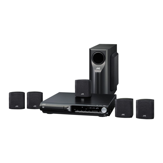
JVC TH-S11 Service Manual
Dvd digital theater system
Hide thumbs
Also See for TH-S11:
- Instructions manual (56 pages) ,
- Service manual (108 pages) ,
- Instructions manual (41 pages)
Table of Contents
Advertisement
SERVICE MANUAL
DVD DIGITAL THEATER SYSTEM
6
2005
MB413
(SP-THS11C)
(SP-THS11F)
Lead free solder used in the board (material : Sn-Ag-Cu, melting point : 219 Centigrade)
1
PRECAUTION. . . . . . . . . . . . . . . . . . . . . . . . . . . . . . . . . . . . . . . . . . . . . . . . . . . . . . . . . . . . . . . . . . . . . . . . . 1-4
2
SPECIFIC SERVICE INSTRUCTIONS . . . . . . . . . . . . . . . . . . . . . . . . . . . . . . . . . . . . . . . . . . . . . . . . . . . . . . 1-7
3
DISASSEMBLY . . . . . . . . . . . . . . . . . . . . . . . . . . . . . . . . . . . . . . . . . . . . . . . . . . . . . . . . . . . . . . . . . . . . . . . 1-8
4
ADJUSTMENT . . . . . . . . . . . . . . . . . . . . . . . . . . . . . . . . . . . . . . . . . . . . . . . . . . . . . . . . . . . . . . . . . . . . . . . 1-23
5
TROUBLESHOOTING . . . . . . . . . . . . . . . . . . . . . . . . . . . . . . . . . . . . . . . . . . . . . . . . . . . . . . . . . . . . . . . . . 1-25
TH-S11
(SP-THS11S)
(XV-THS11)
TABLE OF CONTENTS
COPYRIGHT © 2005 Victor Company of Japan, Limited
Area suffix
C ------------------------- Canada
(SP-WS11)
No.MB413
2005/6
Advertisement
Table of Contents
Troubleshooting

Related Manuals for JVC TH-S11


Summary of Contents for JVC TH-S11
- Page 1 SERVICE MANUAL DVD DIGITAL THEATER SYSTEM MB413 2005 TH-S11 Area suffix C ------------------------- Canada (SP-THS11C) (SP-THS11F) (SP-THS11S) (SP-WS11) (XV-THS11) Lead free solder used in the board (material : Sn-Ag-Cu, melting point : 219 Centigrade) TABLE OF CONTENTS PRECAUTION............... . . 1-4 SPECIFIC SERVICE INSTRUCTIONS .
-
Page 2: Specifications
SPECIFICATION Center unit (XV-THS11) 33 W per channel, RMS at 6 Ω at 1 kHz,with 10% total harmonic dis- Audio section Front/Center/Surround tortion. 40 W, RMS at 4 Ω at 100 Hz, with 10% total harmonic distortion. Subwoofer Video section Video System NTSC Horizontal Resolution... - Page 3 Surround speakers (SP-THS11S) Type 1-Way Bass-Reflex Type 8.0 cm cone × 1 Speaker Power Handling Capacity 33 W 6 Ω Impedance Frequency Range 90 Hz to 20 000 Hz Sound Pressure Level 82 dB/W·m Dimensions (W × H × D) 92 mm ×...
-
Page 4: Precaution
SECTION 1 PRECAUTION Safety Precautions (1) This design of this product contains special hardware and voltmeter. many circuits and components specially for safety purpos- Move the resistor connection to each exposed metal es. For continued protection, no changes should be made part, particularly any exposed metal part having a return to the original design unless authorized in writing by the path to the chassis, and measure the AC voltage across... - Page 5 Preventing static electricity Electrostatic discharge (ESD), which occurs when static electricity stored in the body, fabric, etc. is discharged, can destroy the laser diode in the traverse unit (optical pickup). Take care to prevent this when performing repairs. 1.5.1 Grounding to prevent damage by static electricity Static electricity in the work area can destroy the optical pickup (laser diode) in devices such as laser products.
- Page 6 Importance administering point on the safety Z953 Z952 RY950 B955 B954 B973 B961 B953 CN951 B970 B952 B964 B951 B965 B974 B969 CN952 R990 B957 D958 C960 D956 B956 C961 FW953 Caution: For continued protection against risk of fire, replace only with same type 3A/125V for F950. This symbol specifies type of fast operating fuse.
-
Page 7: Specific Service Instructions
SECTION 2 SPECIFIC SERVICE INSTRUCTIONS This service manual does not describe SPECIFIC SERVICE INSTRUCTIONS. (No.MB413)1-7... -
Page 8: Disassembly
SECTION 3 DISASSEMBLY Main body section 3.1.1 Removing the metal cover (See Figs.1 to 4) (1) From the both sides of the main body, remove the four screws A attaching the metal cover. (See Figs.1 and 2.) Metal cover (2) From the back side of the main body, remove the five screws B attaching the metal cover. -
Page 9: Front Panel Assembly Fig
3.1.2 Removing the front panel assembly (See Figs.5 to 7) • Remove the metal cover. (1) From the right side of the DVD mechanism assembly, push DVD mechanism assembly HP terminal board the slide cam and pull the tray assembly out of the main Main board CN400 body in the direction of the arrow. -
Page 10: No.mb413)1
3.1.3 Removing the DVD mechanism assembly (See Figs.5,6 and 8) • Remove the metal cover. (1) From the right side of the DVD mechanism assembly, push Chassis base DVD mechanism assembly the slide cam and pull the tray assembly out of the main CN404 body in the direction of the arrow. - Page 11 3.1.6 Removing the tuner assembly (See Figs.10 and 11) • Remove the metal cover. (1) From the top side of the main body, disconnect the card wire from the connector on the tuner assembly. (See Fig.10.) (2) From the back side of the main body, remove the two screws G attaching the tuner assembly to the rear panel.
- Page 12 3.1.8 Removing the power amp.boards (See Figs.12 and 13) • Remove the metal cover and video board. (1) From the top side of the main board, remove the three Power amp. board CN100 Main board screws J attaching the heat sink. (See Fig.12.) (2) Disconnect the wire from the connector CN100 on the main...
- Page 13 3.1.9 Removing the main board (See Figs.14 and 15) • Remove the metal cover, video board and heat sink with power amp. boards. Wire clamp CN405 (1) From the top side of the main body, disconnect the card wires from the connectors CN400, CN401 CN403 CN102...
- Page 14 3.1.10 Removing the transformer board (See Fig.16) • Remove the metal cover. (1) From the top side of the main body, disconnect the wires from the connectors CN950, CN952 on the transformer CN101 board. (2) Disconnect the wires from the connectors CN101 on the main board.
- Page 15 3.1.12 Removing the front board (See Figs.18 and 19) • Remove the metal cover and front panel assembly. (1) From the front side of the front panel assembly, pull out the Volume knob volume knob in the direction of the arrow. (See Fig.18.) (2) From the inside of the front panel assembly, remove the six screws T attaching the front board.
- Page 16 DVD mechanism section • Remove the DVD mechanism assembly from the main body. 3.2.1 Removing the traverse mechanism assembly (See Fig.1) From the bottom side of the DVD mechanism assembly, remove the four screws A attaching the traverse mechanism assembly DVD mechanism assembly and take out the traverse mechanism assembly with the DVD Traverse mechanism assembly...
- Page 17 3.2.2 Removing the DVD module board (See Figs.2 and 3) • Remove the traverse mechanism assembly. (1) From the side of the traverse mechanism assembly, solder DVD pickup the short land sections a on the DVD pickup. (See Fig.2.) (2) From the bottom side of the traverse mechanism assem- bly, release the lock of the connector CN101 on the DVD...
-
Page 18: See Figs.2,4 To
3.2.3 Removing the DVD pickup (See Figs.2,4 to 6) • Remove the traverse mechanism assembly. (1) From the side of the traverse mechanism assembly, solder the short land sections a on the DVD pickup. (See Fig.2.) (2) Release the lock of the connector on the DVD pickup in the direction of the arrow and disconnect the card wire. - Page 19 3.2.4 Attaching the DVD pickup (See Figs.2,4 to 7) • See "3.2.3 Removing the DVD pickup". (1) Attach the guide shaft, rack arm and rack arm spring to the Screw shaft gear DVD pickup. (See Fig.6.) (2) Align the DVD pickup to the section h of the traverse mech- anism assembly first, and set the both ends of the guide shaft of the DVD pickup in the sections f and g of the traverse mechanism assembly.
- Page 20 3.2.5 Removing the feed motor (See Figs.4,8 and 9) • Remove the traverse mechanism assembly. (1) From the top side of the traverse mechanism assembly, re- move the screw C and remove the feed bracket from the sections d. (See Fig.4.) (2) Release the claw e of the thrust spring in the direction of the arrow and remove the thrust spring.
-
Page 21: See Fig.
3.2.7 Removing the DVD loading switch board (See Fig.10.) (1) From the bottom side of the DVD mechanism assembly, re- move the wires from the soldered sections n on the DVD DVD loading switch board loading switch board. Tray assembly Wires (2) Remove the screw G attaching the DVD loading switch board. -
Page 22: No.mb413)1
DVD mechanism assembly Tray assembly Fig.13 Motor pulley Belt DVD mechanism assembly Fig.14 1-22 (No.MB413) -
Page 23: Adjustment
SECTION 4 ADJUSTMENT TH-S11 TEST MODE This player has a TEST MODE for product QC, service or repair. Contents as follows. If the DVD TRAY is not completely closed, supply AC power and press POWER ON to close the TRAY. - Page 24 How to repair after carried out full-initialize (1) Learning DVD playback VT-501 (2) Learning CD playback CTS-1000 (3) standby mode (push power key) (4) Checking BCA insert V-2805 test mode (press POWER and STOP button together during AC power plug in) check mode (press menu key of remote controller) BCA check (press +10 key of remote controller) FL indication change "0000 0000"...
-
Page 25: Troubleshooting
SECTION 5 TROUBLESHOOTING This service manual does not describe TROUBLESHOOTING. (No.MB413)1-25... - Page 26 Victor Company of Japan, Limited AV & MULTIMEDIA COMPANY AUDIO/VIDEO SYSTEMS CATEGORY 10-1,1chome,Ohwatari-machi,Maebashi-city,371-8543,Japan (No.MB413) Printed in Japan...
- Page 27 DVD DIGITAL THEATER SYSTEM SYSTÈME CINÉMA NUMÉRIQUE DVD TH-S11 Consists of XV-THS11, SP-WS11, SP-THS11F, SP-THS11C and SP-THS11S Se compose de XV-THS11, SP-WS11, SP-THS11F, SP-THS11C et SP-THS11S INSTRUCTIONS MANUEL D’INSTRUCTIONS GVT0155-014B...
- Page 28 Warnings, Cautions and Others /Mises en garde, précautions et indications diverses ATTENTION CAUTION Afin d’éviter tout risque d’électrocution, d’incendie, etc.: To reduce the risk of electrical shocks, fire, etc.: 1. Ne pas enlever les vis ni les panneaux et ne pas ouvrir le 1.
-
Page 30: Table Of Contents
Table of contents Introduction ........2 Playback ........14 Notes on handling ..............2 Basic playback ..............14 Supplied accessories ............2 One touch replay ..............16 Fast-forward/fast-reverse search ........16 About discs ........3 Skip to the beginning of a desired selection .......16 Playable disc types ...............3 Locating a desired title/group using number buttons ..17 Selecting the desired title/playlist from the control display .. -
Page 31: Introduction
Introduction 7 Safety precautions Notes on handling Avoid moisture, water and dust Do not place the system in moist or dusty places. 7 Important cautions Avoid high temperatures Installation of the system Do not expose the system to direct sunlight and do not place it near •... -
Page 32: About Discs
About discs Region code of DVD VIDEO Playable disc types DVD VIDEO players and DVD VIDEO discs have their own Region Code numbers. This system can play back DVD VIDEO discs whose Region Code numbers include the system’s Region This system has been designed to play back the following discs: Code, which is indicated on the rear panel. - Page 33 About discs For all playable files Notes on MP3 files • The system can only recognize and play files with one of the • Tag information (album name, artist name, and track name) can following extensions, which can be in any combination of upper be shown on the TV.
-
Page 34: Index Of Parts And Controls
Index of parts and controls The numbers in the figures indicate the pages where the details of the parts are described. Front panel (center unit) Display window FM AM L PCM SURR CH RESUME PROGRESSIVE B.S.P. CHAP. TRK PG PL BONUS MONO RDS TA NEWS INFO... -
Page 35: Remote Control
Index of parts and controls Remote control Putting batteries in the remote control STANDBY/ON REPEAT A-B RPT SLEEP Number R6P (SUM-3)/AA (15F) type dry-cell batteries (supplied) buttons:16 TV/VIDEO If the range or effectiveness of the remote control decreases, replace both batteries. DIMMER SURROUND CAUTION... -
Page 36: Connections
Connections Do not connect the power cord until all other connections have been made. If reception is poor Connecting the FM and Center unit AM antennas AM loop antenna 7 AM loop antenna Setting up supplied AM loop antenna Outdoor single vinyl-covered wire antenna (not supplied) If the antenna cord is covered with the insulation 7 FM antenna... -
Page 37: Connecting The Satellite (Front, Center, Surround) Speakers And The Subwoofer
Do not connect the power cord until all other connections have been made. Connections Connecting the satellite (front, center, surround) speakers and the subwoofer Front speakers Center speaker Speaker cord • Connect the black cords to the black (-) terminals. •... -
Page 38: Speaker Layout
Do not connect the power cord until all other connections have been made. Connections 7 To connect a TV equipped with the S-VIDEO and/or Speaker layout the composite video input jacks S-VIDEO cord Center unit Center speaker (not supplied) Front left Front right speaker speaker... -
Page 39: Operating The Tv
Operating the TV You can use the remote control to operate not only this unit but also JVC’s TV. • Refer also to the manuals supplied for the TV. • To operate the TV, aim the remote control directly at the remote sensor on the TV. -
Page 40: Basic Operations
Basic operations The buttons on the remote control are used to explain most of the Turning the system on/off operations in this manual. You can use the buttons on the center unit same as on the remote control for operations unless On the remote control: otherwise noted. -
Page 41: Selecting The Source To Play
See page 11 for button locations. Basic operations Selecting the source to Listening with headphones play (not supplied) On the remote control: CAUTION Press one of the source selecting buttons Be sure to turn down the volume; • Before connecting or putting on headphones as high volume may (DVD/CD3, FM/AM or AUX). -
Page 42: Sleep Timer [Sleep]
In such a case, change the scan mode to “INTER,”. • The adjustments take effect for all sources. To check the compatibility of your TV, contact your local JVC customer service center. • All JVC progressive TVs and High-Definition TVs are fully... -
Page 43: Playback
Playback • The mark shows the types of discs the operation is available Basic playback for. Press 0 on the The buttons described below are used on pages 14 to 17. center unit. • The system turns on and the disc tray comes out. - Page 44 Playback See page 14 for button locations. 7 Playback information on the display window VCD/SVCD/CD Example: DVD VIDEO When a CD is played back Example: When a DVD VIDEO encoded with Dolby Digital 5.1ch is played Signal and speaker Track number indicators Elapsed playing time (hour:minute:second)
-
Page 45: One Touch Replay
See page 14 for button locations. Playback 7 Screen saver Fast-forward/fast-reverse A TV screen may burn out if a static picture is displayed for a long time. To prevent this, the system automatically dims the screen if a search static picture is displayed for over 5 minutes (the screen saver function). -
Page 46: Locating A Desired Title/Group Using Number Buttons
See page 14 for button locations. Playback Locating a desired title/ Selecting the desired group using number title/playlist from the buttons control display 7 During playback or while stopped. 7 During playback or while stopped. Press TOP MENU/PG or MENU/PL. The control display is shown on the TV screen, and the system Press TITLE/GROUP. -
Page 47: Advanced Operations
Advanced operations • The mark shows the types of discs the operation is available Using the surround mode for. 7 Auto Surround (AUTO SURR) The buttons described below are used on pages 18 to 28. This function automatically selects the appropriate surround mode according to the input signals. -
Page 48: Using The On-Screen Bar
See page 18 for button locations. Advanced operations 7 All Channel Stereo 7 When playing back 2 channel source All Channel Stereo (ALL ST) mode can reproduce a larger stereo You can select either mode of Dolby Pro Logic II (MOVIE/ sound field using all the connected (and activated) speakers. -
Page 49: Changing The Time Information
See page 18 for button locations. Advanced operations F Shows playback status. 7 Contents of the on-screen bar during playback appears during playback. DVD VIDEO : appears during fast forward/reverse. : appears during playback in forward slow-motion/ reverse slow-motion. appears when paused. appears when stopped. -
Page 50: Playing From A Specified Position On A Disc
See page 18 for button locations. Advanced operations Press number buttons (1-10, +10) to Playing from a specified select the number of the desired item. position on a disc • For details on using the number buttons, see “How to use the number buttons”. -
Page 51: Using The File Control Display
See page 18 for button locations. Advanced operations Locating a desired position by specifying Using the file control the time display You can locate a desired position by specifying the time from the beginning the disc (while stopped) or the current title/track (during You can search and play desired groups and playback). -
Page 52: Resume Playback
See page 18 for button locations. Advanced operations 7 For MP3: Selecting a view angle During playback or while stopped For JPEG: While stopped 7 During playback of a disc containing multi-view angles Press Cursor 3/2/Y/5 to select the When using the ANGLE button: desired group/track/file. -
Page 53: Selecting The Subtitle
See page 18 for button locations. Advanced operations Selecting the subtitle Selecting the audio 7 During playback of a disc 7 During playback of a disc containing containing subtitles in several audio in several languages languages When using the AUDIO button: When using the SUBTITLE button: Press AUDIO. -
Page 54: Changing The Vfp Setting
See page 18 for button locations. Advanced operations Changing the VFP setting Special picture playback The VFP (Video Fine Processor) function enables you to adjust the picture character Frame-by-frame playback according to the type of programming, picture tone or personal preference. 7 During playback 7 During playback Press 8 repeatedly. -
Page 55: Program Playback
See page 18 for button locations. Advanced operations Press ENTER. To clear the programs one by one from the last entered number Example: Press CANCEL repeatedly. To clear all programs Press 7. You can also clear the program by turning off the system. Press Cursor Y/5 to change the Press DVD/CD3 to start Program setting. -
Page 56: Repeat Playback
See page 18 for button locations. Advanced operations When using the on-screen bar (except for MP3/ Repeat playback JPEG): Press ON SCREEN twice. Repeating the current selection The on-screen bar appears on the TV screen. 7 For DVD VIDEO/DVD VR: Press Cursor 3/2 to highlight During playback Press ENTER. -
Page 57: Tray Lock
See page 18 for button locations. Advanced operations When using the on-screen bar: Balance setting Press ON SCREEN twice. The on-screen bar appears on the TV screen. You can adjust the balance between the front left and front right speakers. Press Cursor 3/2 to highlight NOTE Press ENTER. -
Page 58: Setting Dvd Preferences
Setting DVD preferences NOTE Using the setup menus • See the following “The language codes list” for the code of each language, such as “AA”, etc. • You can change the language used in the setup menus. See “Menu description”. The language codes list Basic operation on the setup menus AA Afar... - Page 59 Setting DVD preferences : Audio menu (AUDIO) : Picture menu (PICTURE) 7 D. RANGE COMPRESSION 7 MONITOR TYPE (Dynamic range compression) You can select the monitor type to match your TV when you play You can enjoy low level recorded sound clearly at night even at a DVDs recorded in the picture’s height/width ratio of 16:9.
- Page 60 Setting DVD preferences : Speaker setting menu : Other setting menu (OTHERS) (SPK. SETTING) 7 RESUME (See page 23.) You can activate or deactivate Resume Playback function. 7 Level menu (LEVEL) FRONT LEFT SPEAKER/FRONT RIGHT SPEAKER/ 7 ON SCREEN GUIDE CENTER SPEAKER/SURROUND RIGHT SPEAKER/ You can activate or deactivate the on-screen guide icons.
-
Page 61: Tuner Operations
Tuner operations The buttons described below are used on pages 32 and Manual tuning REPEAT A-B RPT SLEEP Press FM/AM repeatedly to select the band. Number Example: TV/VIDEO buttons When the system is tuned in to 810 kHz. DIMMER SURROUND 8 1 0 TOP MENU/PG MENU/PL... -
Page 62: Preset Tuning
See page 32 for button locations. Tuner operations Preset tuning Selecting the FM reception mode Once a station is assigned to a channel number, the station can be quickly tuned in. You can preset 30 FM and 15 AM stations. When the stereo FM program currently tuned in is noisy, you can change the FM reception mode to improve the reception. -
Page 63: References
References To clean the disc Maintenance Wipe the disc with a soft cloth in a straight line from center to edge. • DO NOT use any solvent — such as 7 Handling Discs conventional record cleaner, spray, • Remove the disc from its case by holding it thinner or benzine —... -
Page 64: Specifications
References 7 Front speakers (SP-THS11F) Specifications Type: 1-Way Bass-Reflex Type (Magnetically-shielded Type) Speaker: 8.0 cm cone M 1 7 Center unit (XV-THS11) Power Handling Capacity: 33 W Audio section Impedance: 33 W per channel, RMS at 6 C at 1 kHz, Front/Center/Surround: Frequency Range: 90 Hz to 20 000 Hz... - Page 65 EN, FR © 2005 Victor Company of Japan, Limited 0405TMMMDWJEM...
-
Page 66: Parts List
PARTS LIST [ TH-S11 ] * All printed circuit boards and its assemblies are not available as service parts. Area suffix C -------------------------- Canada - Contents - 3- 2 Exploded view of general assembly and parts list (Block No.M1) 3- 5 DVD mechanism assembly and parts list (Block No.MJ) - Page 67 Exploded view of general assembly and parts list Block No. Heatsink side (cover) board Fan bracket board Front board Front support 1 board Front support 2 board HP terminal board...
- Page 68 Power amp. board Main board acket board Holder board Scart terminal board Fix board ront support 2 board Transformer board...
- Page 69 General Assembly Block No. [M][1][M][M] Symbol No. Part No. Part Name Description Local GV10166-029A FRONT PANEL GV30519-005A WINDOW LENS LV40301-001A FELT SPACER (x2) GV10167-001A CONTROL BUTTON GV40121-005A SPACER GV30522-001A VOL RING QYSDSF2608ZA TAP SCREW M2.6 x 8mm QYSDSF2608ZA TAP SCREW M2.6 x 8mm(x6) LV43659-001A FL HOLDER...
- Page 70 DVD mechanism assembly and parts list Block No. Grease =JVG-31N FTU-MM1-21M =JVS-1003 2.4mm + 0.1mm Letter side APPLY AREA 7.0mm + 0.1mm Reverse side module board The parts without symbol number are not service.
- Page 71 DVD mechanism Block No. [M][J][M][M] Symbol No. Part No. Part Name Description Local LV10984-001A S.TM CHASSIS QAR0334-002 S.MOTOR QYSPSPU1740ZA SCREW M1.7 x 4mm(x3) QAR0144-003 MOTOR VKS5557-001 F.M. GEAR QYSPSPT2025ZA SCREW M2 x 2.5mm LV35461-002A MIDDLE GEAR LV44040-001A SCREW SHAFT LV35462-001A SCREW SHAFT GEA QAL0667-001...
- Page 72 DVD loading base assembly and parts list Block No. FMU-MM1-21M Grease JVS-1003 JVG-450 < Back side > Backside CD loading switch board The parts without symbol number are not service.
- Page 73 DVD loading base Block No. [M][N][M][M] Symbol No. Part No. Part Name Description Local LV11065-002A LOADER SUB ASSY E407140-001SS C.D ROLLER E407149-001SS RUBBER TUBE LV10979-002A TRAY LV35499-001A SHAFT GUIDE LV44022-001A SHAFT QYSSSF2008ZA TAP SCREW M2 x 8mm QYSDSF2008ZA TAP SCREW M2 x 8mm(x2) QAR0197-001 MOTOR...
-
Page 74: Electrical Parts List
Electrical parts list Trans board Symbol No. Part No. Part Name Description Local Block No. [0][1] C2756 NDC31HJ-7R0X C CAPACITOR 7pF 50V J Symbol No. Part No. Part Name Description Local C2757 NCB31HK-222X C CAPACITOR 2200pF 50V K C2758 QEKC1CM-106Z E CAPACITOR... - Page 75 Symbol No. Part No. Part Name Description Local Symbol No. Part No. Part Name Description Local R2710 NRSA63J-563X MG RESISTOR 56kΩ 1/16W J R3506 NRSA63J-181X MG RESISTOR 180Ω 1/16W J R2711 NRSA63J-182X MG RESISTOR 1.8kΩ 1/16W J R3507 NRSA63J-201X MG RESISTOR 200Ω...
- Page 76 Symbol No. Part No. Part Name Description Local Symbol No. Part No. Part Name Description Local IC250 BD3814FV-X C904 QETM1VM-338 E CAPACITOR 3300uF 35V M IC260 IMX9-W TRANSISTOR C904 QEZ0743-478 E CAPACITOR 4700uF IC261 IMX9-W TRANSISTOR C905 QETM1VM-338 E CAPACITOR 3300uF 35V M IC262...
- Page 77 Symbol No. Part No. Part Name Description Local Symbol No. Part No. Part Name Description Local C2300 NCB31HK-103X C CAPACITOR 0.01uF 50V K C4104 NCB31HK-103X C CAPACITOR 0.01uF 50V K C2301 NCB31HK-103X C CAPACITOR 0.01uF 50V K C4105 QETN1HM-225Z E CAPACITOR 2.2uF 50V M...
- Page 78 Symbol No. Part No. Part Name Description Local Symbol No. Part No. Part Name Description Local R2253 NRSA63J-333X MG RESISTOR 33kΩ 1/16W J R2855 NRSA63J-473X MG RESISTOR 47kΩ 1/16W J R2254 NRSA63J-102X MG RESISTOR 1kΩ 1/16W J R2856 NRSA63J-473X MG RESISTOR 47kΩ...
- Page 79 Symbol No. Part No. Part Name Description Local Symbol No. Part No. Part Name Description Local R4401 NRSA63J-102X MG RESISTOR 1kΩ 1/16W J C102 NCF31EZ-104X C CAPACITOR 0.1uF 25V Z R4402 NRSA63J-361X MG RESISTOR 360Ω 1/16W J C103 NCF31EZ-104X C CAPACITOR 0.1uF 25V Z...
- Page 80 Symbol No. Part No. Part Name Description Local Symbol No. Part No. Part Name Description Local C379 NCF31EZ-104X C CAPACITOR 0.1uF 25V Z R334 NRSA63J-151X MG RESISTOR 150Ω 1/16W J C380 NCB21CK-105X C CAPACITOR 1uF 16V K R335 NRSA63J-151X MG RESISTOR 150Ω...
- Page 81 DVD loading switch board Block No. [0][4] Symbol No. Part No. Part Name Description Local QGF1016F3-05 CONNECTOR FFC/FPC (1-5) QSW1074-001 DETECT SWITCH 3-16...
- Page 82 < MEMO > 3-17...
- Page 83 Packing materials and accessories parts list Block No. No additional / supplemental order of WARRANTY CARDs are available A2,A3,A4, A1,A7 A5, A6 P8 2/2 The parts without symbol number are not service. 3-18...
- Page 84 Packing and Accessories Block No. [M][3][M][M] Symbol No. Part No. Part Name Description Local GVT0155-014B INST BOOK ENG FRE QAL0014-001 AM LOOP ANT RM-STHS33J REMOCON QAL0457-001 ANT.WIRE ------------ BATTERY (x2) QAM0216-001 SIGNAL CORD ------------ WARRANTY CARD BT-52006-2 CL0020-001 COMPUTER LABEL SPWS11E-SPBOX-W SPEAKER BOX SUBWOOFER...
- Page 85 SCHEMATIC DIAGRAMS DVD DIGITAL THEATER SYSTEM TH-S11 CD-ROM No.SML200506 Area suffix C ------------------------- Canada (SP-THS11C) (SP-THS11F) (SP-THS11S) (SP-WS11) (XV-THS11) Lead free solder used in the board (material : Sn-Ag-Cu, melting point : 219 Centigrade) Contents Block diagram Standard schematic diagrams...
- Page 86 In regard with component parts appearing on the silk-screen printed side (parts side) of the PWB diagrams, the parts that are printed over with black such as the resistor ( ), diode ( ) and ICP ( ) or identified by the " " mark nearby are critical for safety.
- Page 87 < M E M O >...
-
Page 88: Block Diagram
Block diagram TUNER DVD servo contro section A, B, C, D, E1+F1,E2+F2,E3+F3,E4+F4 RF+,RF-,PD(CD),PD(DVD) S2UDT,U2SDT,SCLK,SCS,UCS,CPURST,SCS DVD pickup DAC1OUT,DAC2OUT,DAC3OUT,DAC4OUT,DAC5OUT LPCO1 mechanism LPCO2 LD(CD) CDLDCUR CPURST Q101 LD(DVD) IC302 DVDLDCUR DVDPWR EXDT0 to 15,EXADT0 to 15 D1.2V D1.2V EXADR16 to 20 IC509 Q104 F+/- NEXCE, NEXOE,NEXWE REG. - Page 89 Micom / Audio section Video section TUL,YUR TUCE,TUDI,TUCK,TUDO TUCE DAC1OUT to DAC5OUT TUDI VDMU1 TUCK VIDEO OUT VDMU2 TUDO YCMIX (S-VIDEO/ IC350 VDRGB COMPOSITE) VIDEO DRV. DAC1OUT to DAC5OUT VDMU1,YCMIX DVPWR,U2SDT,S2UDT,SCLK,SCS,UCS,CPURST VIDEO OUT VDRGB,VDMU2 (COMPONENT) FLIN IC215 IC230 FRIN AMP. SELECT SLIN IC235...
- Page 90 Standard schematic diagrams Transeformer section RY950 QSK0124-001 POUT-RELAY D950 C950 D959 QCZ9105-472 1N4003S-T5 1SS355-X STBY5V D955 1N4003S-T5 A+12V Q951 D951 KTB772/Y/ 1N4003S-T5 D953 C954 T950 0.01 R953 UDZS5.6B-X QQT0253-012 Q953 KTC3875/YG/-X Q961 C951 KTC3875/YG/-X 1000/25 R954 R963 D957 1.2K 1N4003S-T5 Q960 Q952 KTC3875/YG/-X...
- Page 91 T901 QQT0484-005 CN952 QGA7901C1-02 T950 0253-012 F950 3A-125V CN950 QGA7901C1-02 C960 R960 3.3M QCZ9079-102 EP950 QNZ0136-001Z SHEET 1...
- Page 92 Regulator section C901 0.1/100 D901 6A10E2 D903 6A10E2 C1000 220/50 D1002 Q1000 1N4003S-T5 KTA1268/GL/-T C1002 C903 0.01 0.1/100 D1000 1N4003S-T5 R1001 3.3K C1003 22/50 D1001 C1001 1N4003S-T5 220/63 D1003 CN102 UDZS27B-X QGA3901C1-08 R1000 C912 0.1/50 R1400 D912 IC110 IC140 KIA7812API KIA278R10PI-U/P 1N5401-TM R1401...
- Page 93 IC160 IC165 KIA278R05PI KIA7805API FANDET 4.7/50 UDZS7.5B-X C1004 D1004 R1610 POUTR FNLCK FANON DVDPWR CN101 QGD2504C1-04Z POUTR IC150 IC155 Q1700 KIA7806API KIA7906PI-U/P KTA1271/OY/-T R1701 R1700 1.5k R1703 C1700 1.5k Q1701 10/16 KRC105S-X FANSW Q1702 KRC101S-X CN100 QGA2501C1-03 FNLCK SHEET 2...
- Page 94 Micon section To SHEET 4 Q4301 QGF120 KRA102S-X D4317 D4316 D4315 R4302 D4314 D4313 R4303 C4102 0.01 R4301 D4312 KEY1 C4100 R4169 KEY2 0.1/16 R4168 Q4303 R4305 KTC3875/YG/-X C4101 0.01 IC410 Q4304 KRA102S-X MN101C49GFR FANDET C4103 POUTR 100/16 DIDT R4110 DICS R4111 DICK...
- Page 95 CN401 QGF1205C1-11 X4500 QAX0868-001Z C4504 RDSCK C4509 330p R4150 TUCE C4505 560p R4149 TUCK RDSID R4148 TUDO RDSDA C4506 R4147 TUDI C4507 10/16 R4146 R4145 RDSID POUTR R4143 R4142 PRT1 R4141 HPDET R4140 FANDET AMPON R4164 PRT2 R4167 PRT3 R4162 SCART-RIN HPSW SCART-LIN...
- Page 96 Audio section R6001 W600 WJZ0163-001A-E Q6001 R2001 KRA104S-X J2000 R6000 QNN0662-001 C2001 330p Q6000 KRA104S-X C2002 330p R2004 C2000 0.01/16 IC211 C2103 RC4558D-X 4.7/25 C2662 IC212 RC4558D-X C2106 C2107 0.1/16 IC265 AUXL C2004 R2105 C2650 RC4558D-X C2659 100/16 4.7/50 C2104 4.3K R2111 R2108...
- Page 97 IC270 STK453-030A R2712 1.2K R2715 C2718 120/1/4W C2709 C2700 Q2700 R2700 0.0022 100/50 KTA1504/YG/-X C2662 1.2K R2721 R2720 R2701 C2719 0.1/16 R2716 R2706 C2659 100/16 R2658 C2704 C2706 C2711 R2714 2.2/50 C2712 470p AMPON C2713 C2714 PRT3 470p 2.2/50 R2717 C2661 R2660 100/16...
- Page 98 Video section R3510 L3500 QQL25CK-221Z C3500 470/10 IC350 BH7868FS-X CN350 QGF1036F1-18 C3502 1/10 VDMU1 C3503 47/16 YCMIX C3504 1/6.3 VDMU1 C3505 22/16 VDMU2 YCMIX VDRGB VDRGB C3506 1/10 C3507 1/10 VDMU2 C3508 1/10 C3509 1/10 2-11...
- Page 99 J3300 R3300 QNN0572-001 R3301 J3300 QNN0572-001 R3302 J3300 QNN0572-001 C3513 470/6.3 J3200 C3200 QNN0557-002 C3512 470/6.3 R3200 470/6.3 R3201 C3511 470/6.3 C3201 0.01/16 C3510 R3202 470/6.3 SHEET 5 2-12...
- Page 100 Front section DI500 QLF0156-001 C5004 0.01 IC500 PT6315 C5006 0.01 QQR0 J5100 QNS0170-001 QQR0 R5100 QQR0 C5104 C5103 C5102 C5101 C5100 0.022 0.01 2-13...
- Page 101 JS500 QSW1059-001 C5001 0.01 CN500 QGF1036F1-19 VOL1 VOL2 C5002 KEY1 47/10 KEY2 C5005 0.01 DICK IC501 GP1UM271XKVF DIDT DICS Q5000 KRC102S-X R5011 R5010 R5009 R5008 6.8k 3.9k 2.4k S5003 S5002 S5001 S5000 QSW1121-001Z QSW1121-001Z QSW1121-001Z QSW1121-001Z R5012 R5013 R5014 R5015 2.4k 3.9k 6.8k...
- Page 102 DVD servo control section (1/2) C372 C102 C373 VREFH DGND C101 R104 R112 E3+F3 E4+F4 4.3K 4.3K E1+F1 C315 EXADT0 E2+F2 NEXCE R115 R107 NEXOE C307 Q103 Q101 Q104 Q102 EXDT0 2SC4617/R/-X R101 2SC4617/R/-X EXDT8 C107 EXDT1 C103 EXDT9 EXDT2 R102 C104 EXDT10...
- Page 103 P3.3V D1.2V IC302 IC302 MM1701CH-X C328 0.01 R327 DGND R330 DACPDN R331 ADCRST DAC1CS DVDPWR R332 DAC2CS R318 SWMUTE TP325 TP320 CPURST C376 TP328 TP329 TP330 TP331 TP332 TP333 TP334 TP335 R362 R357 AOUT0 R364 DATAM C311 R360 AOUT1 R359 AOUT2 R358 R365...
- Page 104 DVD servo control section (2/2) IC505 IC509 SG32M90TFIR3 HY57V641620ETP7 EXADT15 EXADR16 C551 EXADT14 MDQ0 MDQ15 EXADT13 EXADT12 EXDT15 MDQ1 MDQ14 EXADT11 EXDT7 MDQ2 C563 C562 MDQ13 EXADT10 EXDT14 EXADT9 EXDT6 MDQ3 MDQ12 EXADT8 EXDT13 MDQ4 C559 MDQ11 EXADR19 EXDT5 EXADR20 EXDT12 MDQ5 MDQ10...
- Page 105 IC708 R734 K731 DATAM K732 C730 DEMP LRCKM K733 R733 COPY TRACK P3.3V INDEX DAC3OUT K701 NQR0022-002X DAC2OUT K702 NQR0022-002X DAC1OUT K703 NQR0022-002X S3.3V DAC4OUT K704 NQR0022-002X TP702 IC305 DAC5OUT K705 NQR0022-002X MM1563BF-X C380 TP711 K706 NQR0022-005X TP716 TP714 C382 TP713 470p R730...
- Page 106 Loader section QSW1074-001 TO CN405 (SHEET 3) QGF1016F3-05 2-19...
- Page 107 < M E M O > SHEET 9 2-20...
- Page 108 Printed circuit boards Main board Lead free solder used in the board (material : Sn-Ag-Cu, melting point : 219 Centigrade) (Main board) CN405 C4200 R4159 R4126 R4125 R4158 R1700 B2909 R1701 IC413 B2908 D4318 D4102 K4101 B2961 CN404 C1652 CN403 R4163 B2918 B2906...
- Page 109 CN400 R1003 C1003 D1002 CN405 D1001 C4200 D1000 C1400 CN102 D910 C1300 C1101 D913 R1610 C1100 C900 D1500 C910 D900 C1301 C901 C913 IC130 C902 D901 C903 W2001 B2958 D903 R4306 D902 C905 C904 B2911 R2658 D4322 B2972 CN281 D4112 R2653 R2617 C2657...
- Page 110 Trans board Lead free solder used in the board (material : Sn-Ag-Cu, melting point : 219 Centigrade) (Front board) CN500 S5005 R5008 R5013 D5000 C5014 Q5000 S5004 IC501 (Transeformer board) (FL & FR Power Amp. board) (SL & Q953 C954 Q2706 C2740 Q275...
- Page 111 R5014 S5000 S5007 S5001 S5003 S5002 R5011 R5015 R5008 S5006 R5010 R5009 C5009 C5008 CN501 C5005 C5007 R5002 JS500 IC500 C5000 C5001 DI500 (SL & SR Power Amp. board) (CEN & SW Power Amp. board) Q2756 C2790 Q2806 C2840 D2755 D2805 R2790 R2840...
- Page 112 DVD servo control board Lead free solder used in the board (material : Sn-Ag-Cu, melting point : 219 Centigrade) Forward side R117 TP731 TP112 TP108 TP733 Q104 TP109 TP105 C352 TP735 TP110 TP106 R373 TP111 TP107 R112 C351 TP324 R375 R372 TP323 C290...
- Page 113 < M E M O >...
- Page 114 Victor Company of Japan, Limited AV & MULTIMEDIA COMPANY AUDIO/VIDEO SYSTEMS CATEGORY 10-1,1chome,Ohwatari-machi,Maebashi-city,371-8543,Japan Printed in Japan (No.MB413SCH)