Table of Contents
Advertisement
Quick Links
Download this manual
See also:
Setup Manual
Advertisement
Table of Contents

Summary of Contents for Extron electronics SM 3
- Page 1 User Guide Speakers SM 3 Surface Mount Speakers 68-1540-01 Rev. A 05 12...
-
Page 2: Conventions Used In This Guide
ATTENTION: Attention indicates a situation that may damage or destroy the product or associated equipment. NOTE: A note draws attention to important information. Copyright © 2012 Extron Electronics. All rights reserved. Trademarks All trademarks mentioned in this guide are the properties of their respective owners. -
Page 3: Table Of Contents
Removing the Speaker from the Mounting Plate 10 Attaching a Seismic Support Cable ....11 Reference Information ........12 Specifications ............ 12 Parts List ............15 Included Parts ..........15 Optional Accessories ........15 Packaging ............15 SM 3 User Guide • Contents... -
Page 4: Introduction
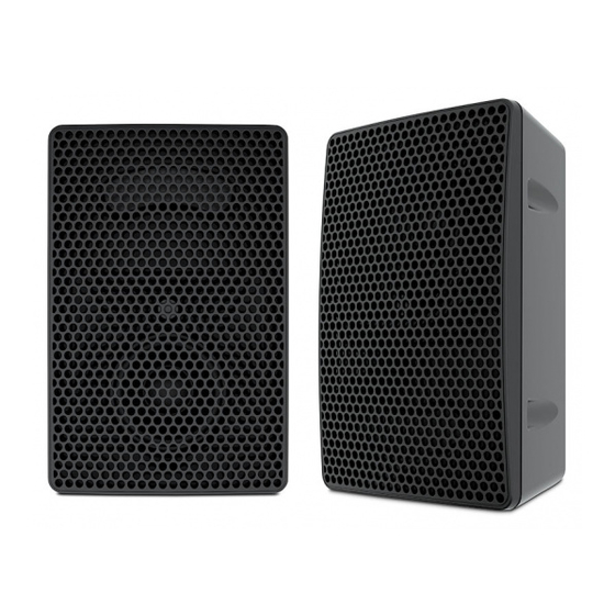
ADA - Americans with Disabilities Act standards for protruding object limits. The SM 3 is sold in pairs and is available in a black or white finish. It includes 0° and 10° mounting plates, and a 5 year parts and labor warranty. -
Page 5: Application Example
(22.2 cm H x 14.6 cm W x 14.2 cm D) • Warranty – 5 year parts and labor warranty Application Example Figure 1 below is one example of configuring a system using the SM 3 speakers. D IS Projector t r o... -
Page 6: Installation
Attaching a Seismic Support Cable Installing the Speaker Mounting Plate The SM 3 speaker comes with two types of speaker mounting plates: • 0° mounting plate — The 0° plate allows the speaker to be mounted flat on a vertical wall with the speaker protruding less than four inches (ADA compliant) from the wall surface (see figure 2 below). -
Page 7: Mounting To A Wall Box
To attach a wall box to wood, use four #8 or #10 screws or 10-penny nails. A minimum of 1/2 inch (1.3 cm) of screw threads must penetrate the wood. Wall Stud Speaker Cables Cable Clamp Screws or Nails Wall opening flush with edge of box Figure 3. Wall box installation SM 3 User Guide • Installation... -
Page 8: Wiring The Speaker Mounting Plate
Quick Connect Contacts Mounting Screws Figure 4. Attaching the mounting plate to a wall box SM 3 User Guide • Installation... - Page 9 (see figure 5 below) to run the wires to the quick connect speaker contacts. 0° Mounting Plate 10° Mounting Plate Alternate Access Point Alternate Access Points Figure 5. Alternate wire access points SM 3 User Guide • Installation...
-
Page 10: Mounting To A Wall Stud
Drill the mounting plate pilot holes and cut the speaker wire access hole, as previously marked. Route the speaker cables through the wall without snagging, being sure to leave enough slack to connect the wires to the mounting plate. SM 3 User Guide • Installation... -
Page 11: Attaching The Speaker To The Mounting Plate
(see figure 7 below). When properly seated, the speaker connections are automatically made. Catch Tab Figure 7. Attaching the speaker SM 3 User Guide • Installation... -
Page 12: Step 2: Using The Security Key To Lock And Unlock The Speaker
Step 2: Using the Security Key to Lock and Unlock the Speaker The SM 3 speaker uses an included security key to lock and unlock the speaker to and from the mounting plate (see figure 8 below). The key has two positions: lock and unlock. The active position of the key is nearest the top of the speaker. -
Page 13: Removing The Speaker From The Mounting Plate
NOTE: Attaching a Seismic Support The speaker may be supported by a safety line (see “ Cable ” in the following section). SM 3 User Guide • Installation... -
Page 14: Attaching A Seismic Support Cable
(see figure 10 below). Insert screw here. Anchor this end to a suitable secure point. Reference only Seismic Support Attach cable here and secure. Cable Figure 10. Attaching a seismic support cable SM 3 User Guide • Installation... -
Page 15: Reference Information
Shipping weight ......Pair: 6 lbs (2.7 kg) with mounting kit package Regulatory compliance Safety ........CE Environmental ......Complies with the appropriate requirements of RoHS, WEEE. Warranty ........5 years parts and labor SM 3 User Guide • Reference Information... - Page 16 SM 3 RESPONSE GRAPHS – FREQUENCY AND IMPEDANCE SPL vs. FREQUENCY dBSPL 20 Hz SPL vs. FREQUENCY – HORIZONTAL OFF-AXIS RESPONSE dBSPL 0 Degrees 10 Degrees 20 Degrees 30 Degrees 40 Degrees 20 Hz IMPEDANCE vs. FREQUENCY 20 Hz SM 3 User Guide • Reference Information...
- Page 17 SM 3 POLAR GRAPHS – 1/3 OCTAVE, HORIZONTAL 100.00 Hz 160.00 Hz 250.00 Hz 400.00 Hz 125.00 Hz 315.00 Hz 200.00 Hz 500.00 Hz 0 Deg 0 Deg -120 -120 -150 -150 100 Hz - 200 Hz 250 Hz - 500 Hz 630.00 Hz...
-
Page 18: Parts List
42-133-02 SM 3 speaker kit, white 42-133-03 SM 3 Setup Guide Optional Accessories Description Part Number SM 3 replacement wall mounting kit, black 70-930-02 SM 3 replacement wall mounting kit, white 70-930-03 Packaging 0° Mounting Plates (2) Security Keys (2) Secondary Attachment 10°... - Page 19 Extron Electronics makes no further warranties either expressed or implied with respect to the product and its quality, performance, merchantability, or fitness for any particular use. In no event will Extron Electronics be liable for direct, indirect, or consequential damages resulting from any defect in this product even if Extron Electronics has been advised of such damage.


