
Related Manuals for Danfoss EFIT 550


Summary of Contents for Danfoss EFIT 550
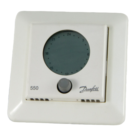
- Page 1 MAKING MODERN LIVING POSSIBLE EFIT 550 User Guide and Installation Manual Danfoss Heating...
- Page 2 Thank you for buying a Danfoss product. With this purchase you have obtained a product of the highest quality, designed to give long lasting comfort at a minimum of environmental impact.
-
Page 3: Table Of Contents
Contents User Guide 1. Basics ....................4 1.1 Safety instructions ..............4 1.2 Functional overview .............5 1.3 Temperature settings ............5 1.4 Changing Battery ..............6 1.5 Operating the child lock ............6 1.6 Switching the thermostat on and off ......7 2. Advanced ..................7 2.1 Optional Settings ..............8 2.2 Troubleshooting .............. -
Page 4: User Guide
User guide 1.0 Basics • The EFIT 550 thermostat controls electrical floor heating elements using a built-in and/or external temperature sensor. • The EFIT 550’s adaptive function automatically optimises the unit for the room within a few days after installation and continuously collects updated room data. -
Page 5: Functional Overview
User guide 1.2 Functional Overview Timer on Child lock on Frost Temperature protection below set value Display Degree symbol Hour display Weekday display Clock setting active Timer setting active Button The thermostat is operated by using the button as follows: Turning clockwise or counter-clockwise to raise or lower values, e.g. -
Page 6: Temperature Settings
User guide 1.3 Temperature Setting Operation without timer: • The hour display appears as an unbroken ring with a blink- ing dot indicating the current time (if set). Raise or lower the temperature. • The set temperature appears on the display. •... -
Page 7: Operating The Child Lock
User guide 1.5 Operating the child lock Press and hold the button. While holding, turn steadily counter-clockwise, until “CODE” appears on the display. Turn clockwise to select “0033”. Press to confirm. appears on the display. • The child lock is on. The thermostat cannot be operated using the button except to switch off the child lock. -
Page 8: Advanced
User guide 2.0 Advanced 2.0.1 Switching the timer on and off The timer is switched on and off by pressing the button. When the timer is on: • appears on the display. • The hour display shows the set comfort temperature peri- ods for the current day as black segments of dots. -
Page 9: Optional Settings
User guide 2.1 Optional Settings 2.1.1 Setting the time and weekday Press and hold for 3 seconds. appears on the display. Set the correct time. • A small dot on the hour display shows the currently set time. • When the set time passes 0:00 in either direction, the weekday display changes to the next or previous day (depending on which direction the button is being turned). - Page 10 User guide Select the weekday where you want the program to start. Press to confirm. Set the starting time of the first comfort temperature period. Press to confirm. Set the duration of the first comfort temperature period. • The duration is shown as a segment of black dots on the hour display.
- Page 11 User guide • You have now defined the starting time, duration, and ending time of the first comfort temperature period. • Repeat as required to define subsequent comfort tempera- ture periods. • When the set time passes 0:00 in either direction, the weekday display changes to the next or previous day (depending on which direction the button is being turned).
-
Page 12: Troubleshooting
User guide Set the minimum floor temperature. Press to confirm. The display returns to normal. • The floor temperature is kept above the set lower limit. 2.2 Troubleshooting • In case of an error, the hour display starts flashing and the weekday display indicates an error code from 2 to 7. -
Page 13: Specifications
User guide 2.4 Specifications Temperature range: +5 to +35 °C or OFF Floor temperature limit: +20 to +50 °C Operation voltage: 180-250 VAC, 50/60 Hz Resistive load: 230 V ~ 16A /3680W ϕ 0,3 = Max. 1A Inductive load: Power consumption: <... -
Page 14: Installation Manual
ALL thermostats in the network must be off! • As the EFIT 550 is not equipped with an earth terminal, the earthing screen of the heating cable and the earthing wire from the mains supply must be connected to the earth terminal in the surface mounted box or recessed metal box. -
Page 15: Installation Guidelines
1.2 Installation guidelines • Dismantle the thermostat before installation and observe the following guidelines: Place the EFIT 550 at a suitable height on the wall. In wet rooms, the thermostat should be installed on an even surface according to local building regulations. -
Page 16: System Overview
Installation manual 2.0 System overview 2.1 Three different sensor configurations FS: Floor sensor (comfort heating) • Suitable for floor heating in e.g. bathrooms. The built-in room sensor is not used. • Comfort heating should be used only to supplement a regular room heating system. -
Page 17: Functional Overview
Installation manual 3.0 Functional overview Release tab Frame Mounting Front cover screws Display Button The thermostat is programmed by pressing and holding the button as follows: Seconds held Function accessed Notes Time and weekday setting Timer setting Minimum floor Only when temperature set- configured to ting... -
Page 18: Installation - Step By Step
Installation manual 4.0 Installation - step by step 4.1 Preparations and guidelines • All necessary cables should be routed to the intended installation point. • The thermostat is designed for installation in a surface mounted box or recessed box with the correct dimensions. •... -
Page 19: Connecting Cables
Frame • Carefully detach the frame. 4.3 Connecting cables • Connect the cables as shown below. Devireg™ 550 NTC sensor Mains supply 180-250 V 50/60 Hz Network connection EFIT 550 ONLY Heating element Max. load 16 Amp. -
Page 20: Mounting And Reassembling The Thermostat
Installation manual • Connect wires in heating element and mains supply cables correctly! • Important! Connect the heating cable screen and the mains supply earthing wire to the mounting box earthing terminal. 4.4 Mounting and reassembling the thermostat Screw holes •... -
Page 21: Activating The Thermostat
Installation manual • Install the display module carefully! • Do NOT over-tighten the mounting screws on the display module. 4.5 Activating the thermostat • Switch on the mains supply. • The unit switches on automatically. • If the unit has never been activated before, configure basic settings as described in section 4.6. - Page 22 5.1. • If a network is not used, choose ALO. Press to confirm. • The adaptive function of the EFIT 550 can be switched off. Select status for adaptive function: • AdAP Adaptive function on • Adaptive function off Press to confirm.
- Page 23 Installation manual • Room and floor sensor • Floor sensor • Room sensor • See descriptions of the possible sensor configurations in section 2.1. Press to confirm. Select the desired maximum floor temperature. • (This does not apply if the thermostat is configured to use a room sensor only.) Press to confirm.
- Page 24 Installation manual • The temperature display can be calibrated (offset) so the thermostat shows the same temperature as another ther- mometer in the room. • (This does not apply if the thermostat is configured to use a floor sensor only.) Select the desired offset value.
- Page 25 Installation manual Press to confirm. • If normal room heating is installed, we recommend lowering the temperature by no more than approx. 5 °C during economy periods. Press to save the settings. • The display returns to normal.
-
Page 26: Optional Settings
Installation manual 5.0 Optional settings 5.1 Network setup Each network must contain one (and only one) master unit (MAS). • All other units must be either slave units (SLA) or independ- ent units (ALO). • Independent units in the network will not respond to or send information to a master unit. - Page 27 Installation manual • Maximum network cable length is 100 m (0.75 mm wire cross section) or 500 m (1.5 mm wire cross section). • The thermostat network can be controlled remotely using e.g. WEB•HOME™ or Danfosscom™ PC Pro. Further informa- tion on how to connect and use these products can be found in the respective user guides.
-
Page 28: Trouble-Shooting Diagram
6.0 Trouble-Shooting Diagram Error code Problem Solution The thermostat is Reconfigure one of the master ther- configured as master in mostats as slave or independent. the local network but has detected another master The thermostat is Reconfigure one of the thermostats configured as slave in as master, or configure all units as the local network but... -
Page 29: Factory Settings
7.0 Factory Settings Item Factory setting Options Network type Alone (ALO) Independent (ALO) Master (MAS) Slave (SLA) Adaptive function On (AdAP) On (AdAP) Off (OFF) Sensor Room + floor sensor Floor sensor (FS) (FS) Room sensor (RS) Room + floor sensor (FS) Max. - Page 30 All work will be invoiced in full if Danfoss is required to inspect or repair faults that have arisen as a result of any of the above.
-
Page 31: Warranty
2 YEAR WARRANTY Warranty Certificate The Danfoss Guarantee is granted to: Name: Address: City: Country: Telephone: Attention: The Warranty Certificate must be completed correctly for the Warranty to be valid. Please read the Warranty conditions on the previous page. Type of thermostat:... - Page 32 Article No.: 088L0358 Version - 04.01 Danfoss A/S Ulvehavevej 61 DK-7100 Vejle Tel: +45 74 88 85 00 Fax: +45 74 88 85 01 www.danfoss.com Danfoss Heating Solutions VISGF202 © Danfoss 02/2009...