Table of Contents
Advertisement
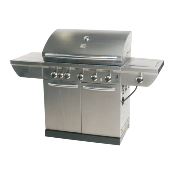
Use & Care Guide
Liquid Propane Gas Grill
Sears Model No. 415.16649010
Safety
•
Parts
•
Use and Care
•
Assembly
•
This Grill is for Outdoor Use Only
WARNING
•
Read and follow all Safety, Assembly,
and Use & Care Instructions in this
Guide before assembling and cooking
with this grill.
•
Failure to follow all instruc tions in this
Use & Care Guide may lead to fire or
explosion, which could result in property
damage, personal injury or death.
Sears Brands Management Corporation, Hoffman Estates, IL 60179 U.S.A.
©2010 Sears Brands, LLC
®
SAVE THESE INSTRUCTIONS!
See our extensive assortment of outdoor living products on-line at
www.sears.com and www.kmart.com
Grill Information Center
Missing Parts? Assembly Questions?
Operation Problems? Before returning
grill to store, call 1-800-241-7548
Tools needed for assembly:
Adjustable wrench (not provided)
Screwdriver (not provided)
7/16" Combination wrench (not provided)
Pliers (not provided)
Caster wrench (provided)
Printed in China
G614-001-020801 • Dec-09-09
Model 464224010
Advertisement
Table of Contents

Related Manuals for Kenmore 415.16649010


Summary of Contents for Kenmore 415.16649010
-
Page 1: Save These Instructions
Use & Care Guide ® Liquid Propane Gas Grill Sears Model No. 415.16649010 Safety • Parts • Use and Care • Assembly • This Grill is for Outdoor Use Only Grill Information Center Missing Parts? Assembly Questions? WARNING Operation Problems? Before returning grill to store, call 1-800-241-7548 •... -
Page 2: For Your Safety
DANGER WARNING CALIFORNIA PROPOSITION 65 If you smell gas: 1. Combustion by-products produced when using 1. Shut off gas to the appliance. this product contain chemicals known to the State of 2. Extinguish any open flame. California to cause cancer, birth defects, and other 3. -
Page 3: Table Of Contents
Congratulations on making a smart purchase. Your new of normal use, accident or improper maintenance. Kenmore® product is designed and manufactured for years of dependable operation. But like all products, it may require repair All warranty coverage is void if this grill is ever used for from time to time. -
Page 4: Use And Care
LP Tank USE AND CARE • The LP Tank used with your grill must meet the following requirements: DANGER • Use LP Tanks only with these required measurements: 12" (30.5cm) (diameter) x 18" (45.7 cm) (tall) with 20 lb. (9 kg.) capacity maximum. - Page 5 LP Tank Exchange Connecting Regulator To The LP Tank • Many retailers that sell grills offer you the option of replacing 1. LP tank must be properly secured onto grill. (Refer to your empty LP tank through an exchange service. Use only assembly section.) those reputable exchange companies that inspect, precision fill, 2.
- Page 6 Leak Testing Valves, Hose and Regulator 1. Turn all grill control knobs to OFF. 2. Be sure regulator is tightly connected to LP tank. 3. Completely open LP tank valve by turning OPD hand wheel counterclockwise. If you hear a rushing sound, turn gas off immediately.
- Page 7 Safety Tips WARNING Before opening LP cylinder valve, check the coupling nut for tightness. When grill is not in use, turn off all control knobs and LP For Safe Use of Your Grill and to Avoid Serious cylinder valve. Injury: Never move grill while in operation or still hot.
- Page 8 Match-Lighting Main Burner Ignitor Lighting Do not lean over grill while lighting. Do not lean over grill while lighting. Open lid. Turn on gas at LP cylinder. 1. Turn OFF all Gas Burner Control Valves. Light Burners one at time. 2.
-
Page 9: Ignitor Check
Burner Flame Check • Cooking surfaces: If a bristle brush is used to clean any of the grill cooking surfaces, ensure no loose bristles remain on • Remove cooking grates and flame tamers. Light burners, rotate cooking surfaces prior to grilling. It is not recommended to knobs from HIGH to low. - Page 10 Cleaning the Burner Assembly Storing Your Grill Follow these instructions to clean and/or replace parts of burner • Clean cooking grates. assembly or if you have trouble igniting grill. • Store in dry location. 1. Turn gas off at control knobs and LP Tank. •...
-
Page 11: Light Operation Instructions
Grill Halogen Light LIGHT OPERATION INSTRUCTIONS 1. Make sure light switch on the control panel is in the “OFF” position. 2. Connect light plug to an extension cord, then put the extension cord plug into the outlet on the wall. 3. -
Page 12: Cleaning The Lens
Cleaning the Lens 1. Prior to cleaning, make sure the light switch is in the “OFF” position and the light plug is disconnected from the power supply. 2. Do not clean the glass lens when warm. Allow to cool before cleaning. Sudden change in temperature may cause cracking of the glass lens. -
Page 13: Parts List
PARTS LIST Key Qty Description Part Number Key Qty Description Part Number LOCKING CASTER G401-0061-W1 TEMPERATURE GAUGE G518-0075-W1 FIXED CASTER G606-0027-W1 HARDWARE F/ TOP LID ASSEMBLY G508-0019-W1 FRONT BRACE G614-6300-W1 BOTTOM SHELF G614-A300-W1 UPPER BACK PANEL, CART G614-0081-W1 DOOR MAGNET ASSEMBLY G501-0016-W1 LEFT SIDE SHELF G614-A800-W1... -
Page 14: Parts Diagram
PARTS DIAGRAM 14 • 464224010... -
Page 15: Assembly
ASSEMBLY Attach the two locking casters at the rear of the bottom shelf and the two fixed casters at the front using the supplied wrench. Fixed caster Caster wrench Qty.1 Locking caster Bottom shelf Attach side panels to bottom shelf using three 1/4-20x1/2”... - Page 16 Attach light adapter to lower back panel using four #8-32x3/8” screws, 4mm flat washers, 4mm lock washers and #8 nuts. #8-32x3/8” screw #8-32x3/8” screw Qty.4 4mm lock washer Qty.4 4mm flat 4mm lock washer washer #8 Nut 4mm flat washer Qty.4 #8 Nut Qty.4...
- Page 17 Attach cart partition panel to bottom shelf using three #10-24x3/8” screws, 5mm lock washers and 5mm flat washers; attach inside shelf to cart partition panel using three #10-24x3/8” screws, 5mm lock washers and 5mm flat washers; attach inside shelf to cart left side shelf using three #10-24x3/8” screws, 5mm lock washers and 5mm flat washers. 5mm lock washer 5mm flat washer #10-24x3/8”...
- Page 18 This step requires two people to lift and position grill head onto cart. Carefully lower the grill head onto the cart, aligning slots at bottom of grill head with posts on cart side panels. Make sure the regulator hose is hanging outside the cart. Grill head must face open side of cart. Post Grill head Before assembly...
- Page 19 Remove the cap and nut from electronic ignition module. Attach electronic ignition module and heat shield to cart left side panel with the nut, shown A. Insert AA battery into ignition module, negative ( ) end first. Then put on the cap, shown B. Untie the 7 burner ignition wires bundled under the right side of grill head.
- Page 20 On back of grill, place cart upper back panel between side panels and above cart lower back panel. ¾ Secure cart upper back panel in lower holes, using one 1/4-20x1 ” screw, 7mm lock washer and 7mm flat washer on each side.
- Page 21 Attach right side shelf to the back of right side fascia using four #10-24x3/8” screws, 5mm lock washers and 5mm flat washers, shown A. Attach sideburner pan to right side shelf using four #10-24x1/2” screws, fiber washers, 5mm flat washers, 5mm lock washers and #10-24 nuts, shown B.
- Page 22 Attach two 1/4-20x5/8” screws, 7mm lock washers and 7mm flat washers on right side of fire box, shown A. Only tighten one-fourth of screw length, so that mounting panel of shelf can slide between fire box and washers in next step. Do not fully tighten the screws.
- Page 23 Secure right side shelf front using two 1/4-20x5/8” screws, 7mm lock washers and 7mm flat washers. Secure top screw first. ¾ Secure right side shelf rear using one 1/4-20x1 ” screw, 7mm lock washer and 7mm flat washer. Only Right side burner shelf assembly shown; repeat step 14 and 15 for Left side shelf. 7mm flat washer 7mm lock washer...
- Page 24 Remove the three #8-32x3/8" screws and 4mm lock washers (pre-assembled to the valve bracket) from the sideburner valve bracket. Position sideburner valve bracket beneath sideburner shelf fascia so that valve stem comes through larger center hole in fascia. Align the lower hole on valve bracket with the lower hole on fascia. Secure using one #8-32x3/8”...
- Page 25 Install ceramic sideburner into right side shelf. Insert sideburner valve into sideburner tube. Secure ceramic sideburner rear to side burner pan using two #10-24x1/2” screws, 5mm flat washers, 5mm lock washers and #10-24 nuts. Make sure that burner tube and sideburner valve are securely engaged. See inset below. 5mm lock washer 5mm flat washer #10-24 nut...
- Page 26 Pull sideburner electrode and wires through the small opening on left side of sideburner pan. Make sure to position electrode end under electrode cover. Secure electrode using one #8-3/4” tapping screw, shown A. Do not overtighten screw to avoid cracking cermic electrode. Attach sideburner heat shield to sideburner pan using two #8-3/8”...
- Page 27 Inside of cart, install grease tray heat shield (w/grease tray rails) by inserting rear shield tabs into slots next to grease tray opening, shown A- . Attach grease tray heat shield front to front brace using two #8-3/8” tapping screws, shown B- Install tank heat shield by inserting rear shield tabs into slots, shown A- .
- Page 28 Insert hinge pin on bottom of doors into hole in bottom shelf. Press upper hinge pin in front brace, align hinge hole on top of door , and release hinge pin into door . Right door Left door PRESS Hinge pin Top of on bottom door...
- Page 29 Install heat diffusers by sliding one end of each heat diffuser into slots at front of firebox and resting opposite end on pins at rear of firebox. Heat diffuser 464224010 • 29...
- Page 30 Place cooking grates onto firebox as shown. Insert the four wire ends at rear of warming rack into holes in back of firebox. Front wires of warming rack rest on sides of firebox. Assembled warming rack Warming rack Cooking grate Place sideburner grate onto sideburner shelf.
- Page 31 On back of grill, slide grease tray into opening in upper back panel. Install sidburner grease tray by sliding it into rails which are under sideburner shelf. CAUTION Failure to install grease tray will cause hot grease to drip from bottom of grill with risk of fire or property damage.
- Page 32 LP CYLINDER IS SOLD SEPARATELY. Fill and leak check the cylinder before attaching to grill and regulator (see Use & Care section). Once cylinder has been filled and leak checked, place cylinder into hole in bottom shelf. Make sure cylinder valve is facing front of grill.
-
Page 33: Troubleshooting
EMERGENCIES: If a gas leak cannot be stopped, or a fire occurs due to gas leakage, call the fire department. EMERGENCIES: If a gas leak cannot be stopped, or a fire occurs due to gas leakage, call the fire department. Emergencies Possible Cause Prevention/Solution... - Page 34 Troubleshooting (continued) Problem Possible Cause Prevention/Solution Burner(s) will not light • Faulty electronic ignition circuit. • See Troubleshooting Integrated Electronic Ignition section. using ignitor. • Sparking somewhere other than • Inspect wire insulation and proper connections. Replace wires if between burner and electrode. insulation is broken.
- Page 35 Troubleshooting - Integrated Electronic Ignition Problem (Ignition) Possible Cause Check Procedure Prevention/Solution SECTION I • Battery not installed • Check battery orientation. • Install battery (make sure that “+” and “–” No sparks appear at properly. connectors are oriented correctly, with “+” end up any electrodes when burner control knobs and “–”...
- Page 36 Get it fixed, at your home or ours! Your Home For expert troubleshooting and home solutions advice: www.managemyhome.com For repair – in your home – of all major brand appliances, lawn and garden equipment, or heating and cooling systems, no matter who made it, no matter who sold it! For the replacement parts, accessories and owner’s manuals that you need to do-it-yourself.