
Related Manuals for Delta 28-190


Summary of Contents for Delta 28-190
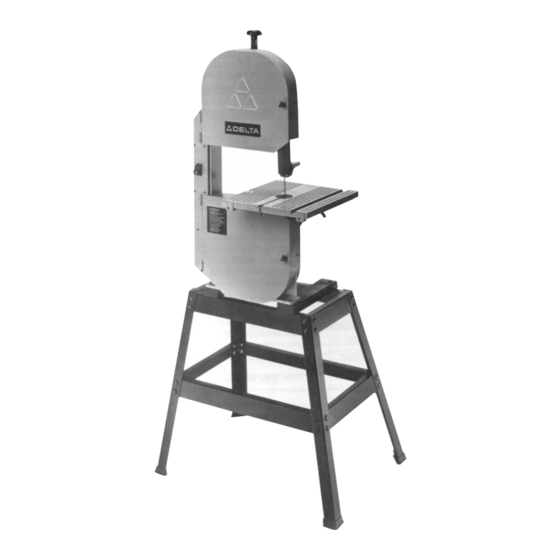
- Page 1 12" Band Saw (Model 28-190) DATED 5-6-98 PART NO. 1345385 © Delta International Machinery Corp. 1995...
-
Page 2: Table Of Contents
TABLE OF CONTENTS SAFETY RULES ..........................3 ADDITIONAL SAFETY RULES FOR BAND SAWS ................4 SPECIFICATIONS ..........................5 UNPACKING ............................5 ASSEMBLY INSTRUCTIONS ......................6 Assembling Stand And Rubber Feet ..................6 Assembling Band Saw To Stand....................6 Assembling Table ........................7 Assembling Upper Blade Guide Assembly ................8 EXTENSION CORDS ........................8 CONNECTING BAND SAW TO POWER SOURCE Power Connections ........................9... -
Page 3: Safety Rules
If you have any questions relative to a particular application, DO NOT use the machine until you have first contacted Delta to determine if it can or should be performed on the product. -
Page 4: Additional Safety Rules For Band Saws
24. THE USE of attachments and accessories not rec- 10. DO NOT attempt to saw stock that does not have a ommended by Delta may result in the risk of injuries. flat surface, unless a suitable support is used. 25. ADDITIONAL information regarding the safe and 11. -
Page 5: Specifications
SPECIFICATIONS Motor: 1/2 H.P., 120V, Single Phase Speed: 2700 SF/M Blade Length: 82" Table: 14" x 14" Capacities: Blade to Frame 12" Table Groove: 3/8" x 3/4" Table to Frame 6" Table Tilt: 46º right / 3º left Height on Stand: 64"... -
Page 6: Assembly Instructions
ASSEMBLY INSTRUCTIONS WARNING: FOR YOUR OWN SAFETY, DO NOT CONNECT THE BAND SAW TO THE POWER SOURCE UNTIL THE MACHINE IS COMPLETELY ASSEMBLED AND YOU HAVE READ AND UNDERSTOOD THE ENTIRE OWNERS MANUAL. ASSEMBLING STAND AND RUBBER FEET 1. Assemble the stand, as shown in Fig. 3, using the 32 carriage bolts, flat washers and nuts supplied. -
Page 7: Assembling Table
3. Using the two 45mm (approximately 1-3/4" long) screws (E) Fig. 6, and flat washers supplied, fasten the band saw to the stand by threading the two screws (E) into the tapped holes in bottom of saw as shown. Fig. 6 4. -
Page 8: Assembling Upper Blade Guide Assembly
3. Replace screw (A) Fig. 10, flat washer (B) and wing nut (C) that was removed in STEP 1. Fig. 10 ASSEMBLING UPPER BLADE GUIDE ASSEMBLY 1. Fasten the upper blade guide assembly (A) Fig. 11, to the side of the band saw using the lock plate (B) and lock screw (C) as shown. -
Page 9: Connecting Band Saw To Power Source
CONNECTING BAND SAW TO POWER SOURCE POWER CONNECTIONS A separate electrical circuit should be used for your tools. This circuit should not be less than #12 wire and should be protected with a 20 Amp fuse. Have a certified electrician replace or repair a worn cord immediately. -
Page 10: Operating Controls And Adjustments
OPERATING CONTROLS AND ADJUSTMENTS STARTING AND STOPPING SAW The switch (A) Fig. 15, is located on the front side of the band saw. To turn the saw “ON” move the switch (A) to the up position. To turn the saw “OFF” move the switch (A) to the down position. -
Page 11: Tracking The Blade
TRACKING THE BLADE For accurate work and maximum blade life, it is important that the blade be centered on the upper band saw wheel. When this adjustment is properly made, the blade will “track”, that is, it will run steady in the same line. -
Page 12: Adjusting Upper Blade Guides And Blade Support Bearing
ADJUSTING UPPER BLADE GUIDES AND BLADE SUPPORT BEARING Fig. 21 Fig. 22 The blade guides must be properly adjusted to prevent the blade from twisting during operation. The upper blade guides and blade support bearing should be adjusted only after the blade is tensioned and tracking properly. -
Page 13: Adjusting Lower Blade Guides And Blade Support Bearing
ADJUSTING LOWER BLADE GUIDES AND BLADE SUPPORT BEARING Fig. 23 Fig. 24 The lower blade guides and blade support bearing should be adjusted at the same time as the upper guides and bearing as follows: 1. DISCONNECT THE SAW FROM THE POWER SOURCE. -
Page 14: Tilting The Table
TILTING THE TABLE 1. The table can be tilted 45 degrees to the right and approximately 3 degrees to the left. To tilt the table, loosen lock handle (A) Fig. 25, tilt the table to the desired angle and tighten lock handle (A). NOTE: The table lock handle (A) can be repositioned by pulling out on the handle and repositioning it on the nut located underneath the hub of the handle. -
Page 15: Changing Blades
CHANGING BLADES To change blades, proceed as follows: 1. DISCONNECT SAW FROM POWER SOURCE. 2. Open upper and lower wheel guards (A) Fig. 28. 3. Release tension on the band saw blade by turning tension knob (B) Fig. 28, counter-clockwise. 4. -
Page 16: Blade Brushes
BLADE BRUSHES Two blade brushes (A) and (B) Fig. 31, are provided to keep the blade and tires clean and free of any build-up of chips. Brush (A) cleans the tire and brush (B) cleans the blade. Adjustment of the brushes can be made by loosening the mounting hardware and adjusting the brushes accordingly. -
Page 18: Warranty
Delta Building Trades and Home Shop Machinery Two Year Limited Warranty Delta will repair or replace, at its expense and at its option, any Delta machine, machine part, or machine accessory which in normal use has proven to be defective in workmanship or material, provided that the customer returns the...