Table of Contents
Advertisement
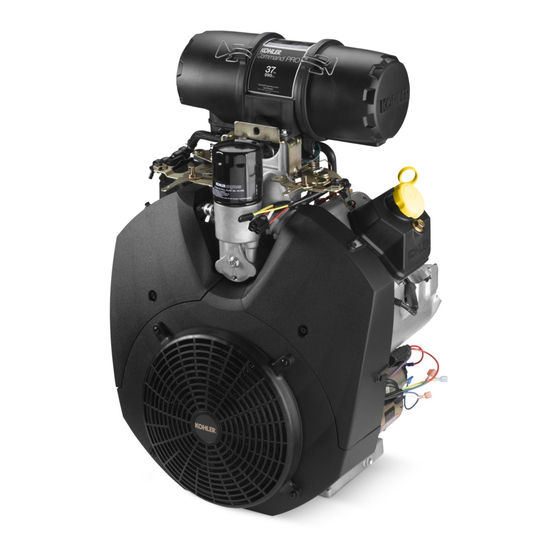
CH940-CH1000
Service Manual
IMPORTANT:
Read all safety precautions and instructions carefully before operating equipment. Refer to operating
instruction of equipment that this engine powers.
Ensure engine is stopped and level before performing any maintenance or service.
2
3
5
Specifi cations
13
16
20
21
28
30
46
55
KohlerEngines.com
1
Advertisement
Table of Contents
Troubleshooting

Related Manuals for Kohler CH940-CH1000


Summary of Contents for Kohler CH940-CH1000
- Page 1 CH940-CH1000 Service Manual IMPORTANT: Read all safety precautions and instructions carefully before operating equipment. Refer to operating instruction of equipment that this engine powers. Ensure engine is stopped and level before performing any maintenance or service. Safety Maintenance Specifi cations...
- Page 2 Safety Safety Precautions WARNING: A hazard that could result in death, serious injury, or substantial property damage. CAUTION: A hazard that could result in minor personal injury or property damage. NOTE: is used to notify people of important installation, operation, or maintenance information. WARNING WARNING WARNING...
- Page 3 Have a Kohler authorized dealer perform this service. Repairs/Service Parts We recommend that you use a Kohler authorized dealer for all maintenance, service, and replacement parts for engine. To fi nd a Kohler authorized dealer visit KohlerEngines.com or call 1-800-544-2444 (U.S. and Canada).
- Page 4 Oil Recommendations Storage If engine will be out of service for 2 months or more We recommend use of Kohler oils for best performance. Other high-quality detergent oils (including synthetic) follow procedure below. of API (American Petroleum Institute) service class SJ 1.
- Page 5 Specifi cations Engine Dimensions with Heavy-Duty Air Cleaner Dimensions in millimeters. Inch equivalents shown in [ ]. 62 690 01 Rev. C KohlerEngines.com...
- Page 6 Specifi cations Engine Dimensions with Low-Profi le Air Cleaner Dimensions in millimeters. Inch equivalents shown in [ ]. KohlerEngines.com 62 690 01 Rev. C...
- Page 7 Specifi cations Engine Identifi cation Numbers Kohler engine identifi cation numbers (model, specifi cation and serial) should be referenced for effi cient repair, ordering correct parts, and engine replacement. Model ..... CH940...
- Page 8 Specifi cations Torques CH940 CH960 CH980 CH1000 Connecting Rod Cap Fastener (torque in increments) 11.3 N·m (100 in. lb.) Control Bracket Mounting Screw (into intake manifold from air cleaner) 9.9 N·m (88 in. lb.) Crankcase Breather Cover Fastener 5.7 N·m (51 in. lb.) Oil Drain Plug 21.4 N·m (16 ft .
- Page 9 Specifi cations Torques CH940 CH960 CH980 CH1000 Solenoid (starter) Mounting Hardware Delco-Remy Starter 4.0-6.0 N·m (35-53 in. lb.) Nut, Positive (+) Brush Lead Delco-Remy Starter 8.0-11.0 N·m (71-97 in. lb.) Starter Assembly Thru Bolt Delco-Remy (solenoid shift) 5.6-9.0 N·m (49-79 in. lb.) Mounting Screw 15.3 N·m (135 in.
- Page 10 Specifi cations Wear Limits CH940 CH960 CH980 CH1000 Connecting Rod-to-Piston Pin Running Clearance 0.015/0.028 mm (0.0006/0.0011 in.) Piston Pin End I.D. @ 70°F 19.023/19.015 mm (0.7489/0.7486 in.) Max. Wear Limit 19.036 mm (0.7494 in.) Governor Cross Shaft Bore I.D. 8.025/8.050 mm (0.3159/0.3169 in.) Max.
- Page 11 Specifi cations Wear Limits CH940 CH960 CH980 CH1000 Governor Cross Shaft O.D. 7.963/8.000 mm (0.3135/0.3149 in.) Max. Wear Limit 7.936 mm (0.3124 in.) Governor Gear Shaft-to-Governor Gear Running Clearance 0.070/0.160 mm (0.0027/0.0063 in.) Governor Gear Shaft O.D. 5.990/6.000 mm (0.2358/0.2362 in.) Max.
- Page 12 Specifi cations General Torque Values English Fastener Torque Recommendations for Standard Applications Bolts, Screws, Nuts and Fasteners Assembled Into Cast Iron or Steel Grade 2 or 5 Fasteners Into Aluminum Size Grade 2 Grade 5 Grade 8 Tightening Torque: N·m(in. lb.) + or - 20% 8-32 2.3 (20) 2.8 (25)
- Page 13 Here is a list of tools and their source. Separate Tool Suppliers: Kohler Tools SE Tools Design Technology Inc. Contact your local Kohler source of 415 Howard St. 768 Burr Oak Drive supply. Lapeer, MI 48446 Westmont, IL 60559...
- Page 14 For reaming worn valve guides to accept replacement oversize valves. Can be used in low-speed drill press or with handle below for hand reaming. Design Technology Inc. Reamer Handle For hand reaming using Kohler 25 455 12-S reamer. DTI-K830 SE Tools KLR-82415 Valve Guide Service Kit (Courage, Aegis, Command, OHC) For servicing worn valve guides.
- Page 15 Tools and Aids Flywheel Holding Tool Rocker Arm/Crankshaft Tool A fl ywheel holding tool can be made out of an old junk A spanner wrench to lift rocker arms or turn crankshaft fl ywheel ring gear and used in place of a strap wrench. may be made out of an old junk connecting rod.
-
Page 16: Troubleshooting
Troubleshooting Troubleshooting Guide When troubles occur, be sure to check simple causes which, at fi rst, may seem too obvious to be considered. For example, a starting problem could be caused by an empty fuel tank. Some general common causes of engine troubles are listed below and vary by engine specifi cation. Use these to locate causing factors. - Page 17 Troubleshooting Engine Loses Power External Engine Inspection ● Dirty air cleaner element. NOTE: It is good practice to drain oil at a location away ● Engine overheated. from workbench. Be sure to allow ample time for ● Excessive engine load. complete drainage.
- Page 18 Troubleshooting Basic Engine Tests A partial vacuum should be present in crankcase when engine is operating. Pressure in crankcase (normally caused by a clogged or improperly assembled breather) can cause oil to be forced out at oil seals, gaskets, or other available spots.
- Page 19 Troubleshooting Compression Test A compression test is best performed on a warm engine. Clean any dirt or debris away from base of spark plug(s) before removing them. Be sure choke is off, and throttle is wide open during test. Compression should be at least 160 psi and should not vary more than 15% between cylinders.
-
Page 20: Air Cleaner/Intake
Air Cleaner/Intake These systems are CARB/EPA certifi ed and components Air Cleaners should not be altered or modifi ed in any way. NOTE: Operating engine with loose or damaged air cleaner components could cause premature Low-Profi le Air Cleaner wear and failure. Replace all bent or damaged components. - Page 21 Fuel System and Governor Typical carbureted fuel system and related components include following: ● Fuel Tank and Valve ● In-line Fuel Filter ● Carburetor ● Fuel Lines ● Fuel Pump Fuel from tank is moved through in-line fi lter and fuel lines by fuel pump. Fuel then enters carburetor fl oat bowl and is drawn into carburetor body and mixed with air.
- Page 22 Fuel System and Governor Fuel Recommendations Fuel Line Low permeation fuel line must be installed on carbureted Kohler Co. engines to maintain EPA and CARB WARNING regulatory compliance. Explosive Fuel can cause fi res and severe burns. Fuel Pump Do not fi ll fuel tank while engine is hot or These engines use either a mechanical fuel pump, or running.
- Page 23 Fuel System and Governor Carburetor Troubleshooting Checklist When engine starts hard, runs roughly, or stalls at low WARNING idle speed, check following areas before adjusting or disassembling carburetor. Explosive Fuel can cause fi res and severe burns. ● Make sure fuel tank is fi lled with clean, fresh gasoline.
- Page 24 Fuel System and Governor Fuel Shut-off Solenoid Carburetor Adjustments Most carburetors are equipped with a fuel shut-off NOTE: Carburetor adjustments should be made only solenoid. Solenoid is attached to fuel bowl. Solenoid has after engine has warmed up. a spring-loaded pin that retracts when 12 volts is applied Carburetor is designed to deliver correct fuel-to-air to lead, allowing fuel fl...
- Page 25 Fuel System and Governor 6. Remove screw securing fl at washer and ground lead Carburetor Servicing (if equipped), from top of carburetor; then carefully pull (lift) out two slow jets. Slow jets may be sized/ side specifi c. Mark or tag jets for proper reassembly. WARNING Note small O-ring on bottom of each jet.
- Page 26 1219 meters (4000 ft.). To obtain high blow out internal channels and ports. Do not use altitude kit information or to fi nd a Kohler metal tools or wire to clean orifi ces and jets. Inspect authorized dealer visit KohlerEngines.com or call and thoroughly check carburetor for cracks, wear, or 1-800-544-2444 (U.S.
- Page 27 Fuel System and Governor Governor Adjustments NOTE: Do not tamper with governor setting. Overspeed is hazardous and could cause personal injury. Initial Adjustment Procedure Make this adjustment whenever governor arm is loosened or removed from cross shaft. Adjust as follows: 1.
-
Page 28: Lubrication System
Oil Recommendations Check Oil Level NOTE: To prevent extensive engine wear or damage, We recommend use of Kohler oils for best performance. never run engine with oil level below or above Other high-quality detergent oils (including synthetic) operating range indicator on dipstick. - Page 29 Lubrication System Change Oil and Oil Filter Oil Sentry (if equipped) ™ Change oil while engine is warm. This switch is designed to prevent engine from starting in a low oil or no oil condition. Oil Sentry may not shut 1.
-
Page 30: Electrical System
Electrical System Spark Plugs NOTE: Do not clean spark plug in a machine using abrasive grit. Some grit could remain in spark plug and enter engine causing extensive wear and damage. Engine misfi re or starting problems are often caused by a spark plug that has improper gap or is in poor condition. - Page 31 Electrical System Inspection Inspect each spark plug as it is removed from cylinder head. Deposits on tip are an indication of general condition of piston rings, valves, and carburetor. Normal and fouled plugs are shown in following photos: Normal Worn Carbon Fouled A plug taken from an engine On a worn plug, center electrode will...
- Page 32 Electrical System Battery Size Recommendations Battery Temperature Battery Required A 12-volt battery with 400 cold cranking amps (cca) is generally recommended for starting in all conditions. A Above 32°F (0°C) 300 cca minimum smaller capacity battery is often suffi cient if an 0°F to 32°F (-18°C to 0°C) 300 cca minimum application is started only in warmer temperatures.
- Page 33 2. Test for spark on both cylinders with Kohler ignition 2. If one side is not fi ring, check all wiring, connections, tester. Disconnect one spark plug lead and connect and terminations on that side.
- Page 34 Electrical System Troubleshooting -- Electric Ignition System Test Conclusion Check Ignition System If problem goes away, electrical system on equipment is suspect. Check key switch, wires, NOTE: If engine starts or runs during any of testing, you may connections, safety interlocks, etc. need to ground kill lead to shut it down.
-
Page 35: Rev. C
Electrical System Electron CD Fixed Ignition Timing System Digital Spark Advance Ignition (DSAI) System SWITCH, KEY B-BATTERY LIGHT ASSEMBLY, INDICATOR A-ACCESSORY STARTER (OPTIONAL) GROUND OIL PRESSURE SWITCH (OPTIONAL) M-MAGNETO YELLOW WIRES OIL SENTRY R-RECTIFIER LIGHT BLUE WIRE YELLOW BLACK BLACK WIRE WHITE WIRES RED WIRE GREEN... - Page 36 Electrical System Wire Diagram-15/20/25 Amp Regulated Battery Charging System with Fixed Timing, Four Pin Connector KohlerEngines.com 62 690 01 Rev. C...
- Page 37 Electrical System Wire Diagram-15/20/25 Amp Regulated Battery Charging System with Fixed Timing, Five Pin Connector, Key Switch, and Fuse. 62 690 01 Rev. C KohlerEngines.com...
- Page 38 Electrical System Wire Diagram-15/20/25 Amp Regulated Battery Charging System with DSAI Ignition, Five Pin Connector and Key Switch KohlerEngines.com 62 690 01 Rev. C...
- Page 39 Electrical System Wire Diagram-15/20/25 Amp Regulated Battery Charging System with DSAI Ignition and Four Pin Connector (LP-NG Kohler Power Systems Application) 62 690 01 Rev. C KohlerEngines.com...
- Page 40 Electrical System Wire Diagram-15/20/25 Amp Regulated Battery Charging System with DSAI Ignition and Five Pin Connector (Gasoline/LP-NG Non-Kohler Power Systems Application) KohlerEngines.com 62 690 01 Rev. C...
- Page 41 Electrical System Battery Charging System NOTE: Observe following guidelines to avoid damage to electrical system and components: ● Make sure battery polarity is correct. A negative (-) ground system is used. ● Disconnect rectifi er-regulator plug and/or wiring harness plug before doing any electric welding on equipment powered by engine.
- Page 42 Electrical System Troubleshooting Guide NOTE: Always zero ohmmeter on each scale before testing to ensure accurate readings. Voltage tests should be made with engine running at 3600 RPM - no load. Battery must be good and fully charged. 15/20/25 Amp Battery Charging Systems When problems occur in keeping battery charged or battery charges at too high a rate, problem can usually be found somewhere in charging system or with battery.
- Page 43 Electrical System Electric Starting Motors Engines in this series use solenoid shift starters. A Delco-Remy solenoid shift starter is typically used. Starting Motor Precautions NOTE: Do not crank engine continuously for more than 10 seconds. Allow a 60 second cool down period between starting attempts.
- Page 44 Electrical System Starter Disassembly Delco-Remy Starters NOTE: Test procedure for checking starter solenoid. NOTE: Do not reuse old retainer. NOTE: Do not soak armature or use solvent when cleaning. Wipe clean using a soft cloth, or use compressed air. 1. Remove hex nut and disconnect positive (+) brush lead/bracket from solenoid terminal.
- Page 45 Pinion teeth for abnormal wear or damage. Brushes and springs are serviced as a set (4). Use b. Surface between pinion and clutch mechanism a new Kohler Brush and Spring Kit, if replacement is for nicks, or irregularities which could cause seal necessary.
- Page 46 Electrical System 8. Install frame, with small notch forward, onto armature and drive end cap. Align notch with corresponding section in rubber grommet. Install drain tube in rear cutout, if it was removed previously. 9. Install fl at thrust washer onto commutator end of armature shaft. 10.
- Page 47 Disassembly WARNING Accidental Starts can cause severe injury or Before working on engine or equipment, disable engine as death. follows: 1) Disconnect spark plug lead(s). 2) Disconnect negative (–) battery cable from battery. Disconnect and ground spark plug lead(s) before servicing. Heavy-Duty Air Cleaner Low-Profi...
- Page 48 Disassembly Clean all parts thoroughly as engine is disassembled. 3. Carefully pry off pal nut, remove two washers Only clean parts can be accurately inspected (note assembly order), and disconnect choke linkage and gauged for wear or damage. There are many from pivot lever.
- Page 49 1. Remove screw and grommet securing each valve or keyway is damaged. cover. Inspect ring gear for cracks or damage. Kohler does not 2. Remove valve cover and gasket from each cylinder provide ring gear as a serviceable part. Replace fl ywheel head.
- Page 50 Check base surface of hydraulic lifters for wear or damage. If lifters need to be replaced, apply a liberal To check valve guide-to-valve stem clearance, coating of Kohler lubricant to base of each new lifter thoroughly clean valve guide and, using a split-ball before it is installed.
- Page 51 Disassembly Lapping Valves Oil Pump Assembly Reground or new valves must be lapped in, to provide proper fi t. Use a hand valve grinder with a suction cup for fi nal lapping. Lightly coat valve face with a fi ne grade of grinding compound, then rotate valve on its seat with grinder.
- Page 52 Disassembly Reassembly Inspection and Service 1. Make sure recess in closure plate for oil pump Check bearing area (big end) for excessive wear, score gerotor gears is clean. marks, running and side clearances. Replace rod and cap if scored or excessively worn. 2.
- Page 53 Disassembly Ring failure is usually indicated by excessive oil 1. Oil control ring (bottom groove): Install expander and consumption and blue exhaust smoke. When rings fail, then rails. Make sure ends of expander are not oil is allowed to enter combustion chamber where it is overlapped.
- Page 54 Disassembly Inspect crankshaft keyways. If they are worn or chipped, Remove Lifter Feed Chamber Cover and Gaskets replacement of crankshaft will be necessary. Remove three screws securing lifter feed chamber Inspect crankpin for score marks or metallic pickup. baffl e (some models only), cover, and gaskets. Carefully Slight score marks can be cleaned with crocus cloth separate parts from crankcase.
- Page 55 Measuring Piston-to-Bore Clearance NOTE: Kohler pistons are custom-machined to exacting 11 mm (0.433 in.) tolerances. When oversizing a cylinder, it should be machined exactly 0.25 mm (0.010 in.) or 0.50 mm (0.020 in.) over new diameter.
- Page 56 Reassembly General Install Governor Shafts, Seal, and Governor Gear NOTE: Make sure engine is assembled using all Seal Depth specifi ed torque values, tightening sequences, 1.5-2.0 mm (0.059-0.078 in.) and clearances. Failure to observe specifi cations could cause severe engine wear or damage. Always use new gaskets.
- Page 57 Reassembly Install Connecting Rods with Pistons and Rings Install Camshaft 1. Liberally apply camshaft lubricant to each cam lobe. Top of Piston Lubricate camshaft bearing surfaces of crankcase and camshaft with engine oil. 2. Position timing mark of crankshaft gear at 12 o’clock position.
- Page 58 Reassembly 5. Orient fl at of oil pump gear to match position of fl at Oil Seal on camshaft. Then install closure plate to crankcase. Carefully seat camshaft and crankshaft into their mating bearings. Rotate crankshaft slightly to help oil pump and governor gears mesh.
- Page 59 Reassembly Used on Serial No. 37070xxxxx and Below Used on Serial No. 37071xxxxx and Higher Breather Fastener Torque Sequence Filter Mist Not Extend Above Casting SECTION A-A Breather Hose Flange Nuts Breather Gasket Screw Baffl e Filter Adapter Studs Install Breather Assembly Install Hydraulic Lifters 1.
- Page 60 1. Check to make sure there are no nicks or burrs on Install Spark Plugs sealing surfaces of cylinder head or crankcase. 1. Use new Kohler spark plugs. 2. Check dowel pins are in place in two lower locations, and install a new cylinder head gasket, 2.
- Page 61 Reassembly Install Oil Filter Adapter Install Oil Filter Housing Assembly Reassemble oil fi lter housing if disassembled previously. Reassembly 1. Install small spring onto rubber valve, and insert small end through corresponding hole in cup until properly seated. 2. Install larger spring into fi lter housing. 3.
- Page 62 Reassembly Install Flywheel Install Outer Cylinder Baffl es 1. Install outer cylinder baffl es. Make sure spark plug WARNING: Damaging Crankshaft and Flywheel Can lead is routed through corresponding opening in Cause Personal Injury! each baffl e. Start each screw. Tighten M6 shoulder screws going through backing shroud assembly into Using improper procedures to install fl...
- Page 63 Reassembly 1. Position control bracket assembly onto two intake Install Valley Baffl es manifold bosses. Align rear supports with top valley Install two valley baffl es and secure with mounting baffl e/cylinder head mounting screw locations and screws. Lower section should fi t under outer baffl e. install two screws, but do not fully tighten.
- Page 64 Reassembly Governor Spring/RPM Chart Install Oil Filter and Add Oil to Crankcase NOTE: Make sure both oil drain plugs are installed and CH940-CH1000 tightened to torque specifi cations to prevent oil Governor Idle Spring Color) High Speed (RPM) leakage. Clear 1400-1625 RPM 1.
- Page 65 FORM NO.: 62 690 01 Rev. C ISSUED: 9/10 REVISED: 5/11 FOR SALES AND SERVICE INFORMATION IN U.S. AND CANADA, CALL 1-800-544-2444 KohlerEngines.com ENGINE DIVISION, KOHLER CO., KOHLER, WISCONSIN 53044 © 2011 by Kohler Co. All rights reserved.