Table of Contents
Advertisement
Quick Links
tekmarNet
®
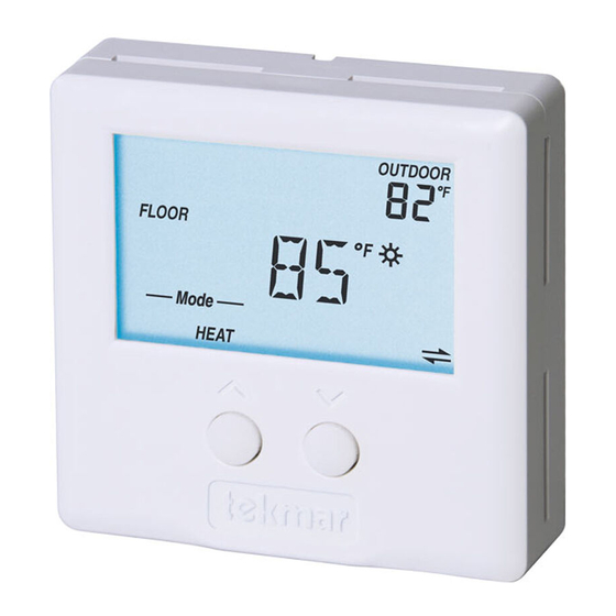
2 Thermostats 527, 528, 530
Installation & Operation Manual
Introduction
This Installation and Operation Manual includes detailed wiring instructions, settings and operational features of the
®
tekmarNet
2 Thermostats 527, 528 and 530. These 2-wire thermostats are part of a complete tekmarNet
OUTDOOR
F
FLOOR
F
HEAT
Thermostat 527
•
One Stage Heat
•
Cooling Group Member
•
Dual Temperature Display
•
Simple Temperature Adjustment
Thermostat 528
•
One Stage Heat
•
Cooling Group Member
•
Auxiliary Sensor Input
•
Floor Minimum & Maximum
•
Dual Temperature Display
•
Local Override Button
Thermostat 530
•
One-Stage Heat
•
One Stage Cool
•
Fan Operation
•
Cooling Group Master
•
Dual Temperature Display
•
Local Override Button
1 of 28
Features
®
•
tekmarNet
communications compatibility
•
Simple 2-wire connectivity
•
Schedule member
•
Optimum start
•
Scenes
•
Outdoor temperature display
•
Freeze protection
•
Cooling groups
•
Exercising
•
Zone synchronization
•
Large LCD with backlight
•
CSA C US approved for use in USA
and Canada
Benefits
•
Energy savings
•
Reduced temperature swings
•
Suitable for 2-wire retrofits
•
Compatible with tekmarNet Timers,
User Switches and Gateway for
additional control options
•
Interlock to prevent simultaneous
heating & cooling
Note
•
tN2 Zone Manager, Expansion Module
Wiring Center or House Control
required for operation
© 2009
D 527
06/09
®
system.
D 527 - 06/09
Advertisement
Table of Contents

Related Manuals for Tekmar 527


Summary of Contents for Tekmar 527
- Page 1 Introduction This Installation and Operation Manual includes detailed wiring instructions, settings and operational features of the ® ® tekmarNet 2 Thermostats 527, 528 and 530. These 2-wire thermostats are part of a complete tekmarNet system. Features Thermostat 527 ® •...
-
Page 2: Table Of Contents
® Address ..........22 Button Operation ........... 10 Cool Group Master (530 Only) ......23 Setting the Temperature ........10 Cool Group Member (527 and 528 Only) ....23 User Settings ............11 Troubleshooting Guide ..........24 Adjust Menu ............12 Testing the Wiring ............ -
Page 3: Caution
An approved circuit breaker or power disconnect that de-energizes the high voltage wiring should be located near the Zone Manager, and marked as the 115 V (ac) power disconnect for this device. 3 of 28 © 2009 D 527 - 06/09... -
Page 4: Rough-In Wiring
Stud 007 Adaptor Stud Plate Thermostat Base Thermostat Switch Base Thermostat Thermostat ” (83 mm) Wall ” ” (60 mm) (60 mm) screwhole screwhole Mounted on switch box Mounted on wallboard © 2009 D 527 - 06/09 4 of 28... -
Page 5: Thermostat Displays
This display shows all potential symbols that may show up on your thermostat. They will be referred to throughout this manual, so it is a good idea to become familiar with those that are applicable to your thermostat model (527, 528 or 530). -
Page 6: 527 Thermostat
527 Thermostat Wiring The Thermostat 527 operates a single hydronic heating system zone. 527 tNt tNt 527 One Stage Heat For instructions see brochure Reset Menu Use at least 65°C conductors Made in Item Zone Canada Module 1 2 3 4... -
Page 7: Button Operation
Press the or the button to select the desired The Away temperature cannot be changed temperature for the current operating temperature. The temperature range is from 40°F (4.5°C) to 85°F (29.5°C). 7 of 28 © 2009 D 527 - 06/09... -
Page 8: User Settings
Synchronization • There is no tekmarNet ® System Control on the system. STEP 5 The large number shows the type number as 527. View Type and Software The software version is shown in the upper right hand corner. Version ®... -
Page 9: 528 Thermostat
528 One Stage Heat Thermostat 528 DIP Switches For instructions see brochure Use at least 65°C conductors Made in 1 2 3 4 Canada 1 2 3 4 9 of 28 © 2009 D 527 - 06/09... -
Page 10: Button Operation
If a symbol does not appear, there is no schedule available. Schedules are provided by tekmarNet ® Timers or Thermostats that are connected to the Zone Manager, Expansion Module or Wiring Center. © 2009 D 527 - 06/09 10 of 28... -
Page 11: User Settings
STEP 5 The address can be returned to automatic “Au” between addresses 24 and 1. Manually Change tekmarNet ® Address Ensure to document the address number when manually addressing thermostats. 11 of 28 © 2009 D 527 - 06/09... -
Page 12: Adjust Menu
Room Sensor setting in the Adjust menu is set to On AND Default = 85°F (29.5°C) • A slab sensor is installed on the auxiliary sensor input AND • Switch setting 4 is set to Floor (On position). Continued on next page. © 2009 D 527 - 06/09 12 of 28... - Page 13 Thermostat can follow schedule 1, 2, 3, or 4. Default = 1 Available when: • Switch setting 1 is set to Setback (On Position). After the last item, the control returns to the first item in the Adjust menu. 13 of 28 © 2009 D 527 - 06/09...
-
Page 14: 530 Thermostat
One Stage Cool / One Fan Thermostat 530 DIP Switches Relays: 24V (ac) 2A For instructions see brochure Use at least 65°C conductors Made in 1 2 3 4 Canada 1 2 3 4 © 2009 D 527 - 06/09 14 of 28... -
Page 15: Button Operation
If a symbol does not appear, there is no schedule ® available. Schedules are provided by tekmarNet Timers or Thermostats that are connected to the Zone Manager, Expansion Module or Wiring Center. 15 of 28 © 2009 D 527 - 06/09... -
Page 16: User Settings
STEP 5 The address can be returned to automatic “Au” between addresses 24 and 1. Manually Change tekmarNet ® Address Ensure to document the address number when manually addressing thermostats. © 2009 D 527 - 06/09 16 of 28... -
Page 17: Adjust Menu
VENTILATION OFF, On Select whether or not ventilation is required. When turned On, fan Default = OFF operation can be customized with the next two Fan settings. Continued on next page. 17 of 28 © 2009 D 527 - 06/09... - Page 18 Thermostat can follow schedule 1, 2, 3, or 4. Default = 1 Available when: • Switch setting 1 is set to Setback (On Position). After the last item, the control returns to the first item in the Adjust menu. © 2009 D 527 - 06/09 18 of 28...
-
Page 19: Sequence Of Operation For All Tn2 Thermostats
A percent run time can be selected if Ventilation is set On in the Adjust Menu. “Auto” is equivalent to Off when in Vent Mode. 19 of 28 © 2009 D 527 - 06/09... -
Page 20: Schedules (Requires Schedule Device)
Communication System schedules. Thermostats 528 and 530 can follow system Control schedule 1, 2, 3, or 4. Thermostat 527 can only follow system schedule 1. Optimum Start When a programmable schedule is selected, there is a time The Optimum Start applies for both the heating and the... -
Page 21: Cycles Per Hour / Synchronization
System Control, the Heating Cycles Per Hour setting in the Adjust menu allows the installer to select Auto or Sync. Indoor Temperature Feedback The 527, 528 and 530 Thermostats can provide indoor Indoor Temperature Feedback also allows the room temperature feedback to a tekmarNet ®... -
Page 22: Thermal Motor Zone Valves
Delay setting is located in the Adjust Menu of 528 or 530 open before the system pump is turned on. If the thermostat thermostats. It is located on DIP switch 4 of a 527. Backlight The backlight can be adjusted using the “lite” setting. Select backlight for 30 seconds after a button is pressed. -
Page 23: Cool Group Master (530 Only)
The cool group master operates the cooling equipment for the group. Thermostats 527 and 528 can be To join “Cool Group 1”, set switch 3 to “Cool Member 1” members of ‘Cool Group 1’, allowing them to be included (down). -
Page 24: Troubleshooting Guide
The built-in air temperature sensor has a short circuit fault. If a floor sensor is present (Thermostat 528 only), heating will operate to satisfy floor min. This error cannot be field repaired. Contact your wholesaler or tekmar sales representative for details on the repair procedures. -
Page 25: Testing The Wiring
A good quality electrical test meter, capable of reading from at least 0-300 V (ac), 0-2,000,000 Ohms, and testing for continuity is essential to properly test the wiring and sensors. 25 of 28 © 2009 D 527 - 06/09... -
Page 26: Cleaning The Thermostat
0 V (ac). This thermostat is not compatible Center are operating correctly. The thermostat may with 24 V (ac) equipment. have a fault. Contact your local tekmar representative for assistance. 3. Use an electrical test meter to measure DC voltage between the tN2 terminals for 20 seconds. -
Page 27: Warranty
NTC thermistor, 10 kΩ @ 77°F (25°C ± 0.2°C) ß = 3892 – Included None – Optional tekmar type # 071, 070, 072, 073, 076, 077, 078, 079, 082, 083, 084 ® tekmarNet 2 Thermostat 530: One Stage Heat, One Stage Cool, One Fan Control Microprocessor PID control;... - Page 28 Purchaser shall indem- such Product sale and acknowledges that it has read nify and hold tekmar harmless from and against any and all and understands same. claims, liabilities and damages of any kind or nature which...