
Related Manuals for Husqvarna 115 312526R1


Summary of Contents for Husqvarna 115 312526R1
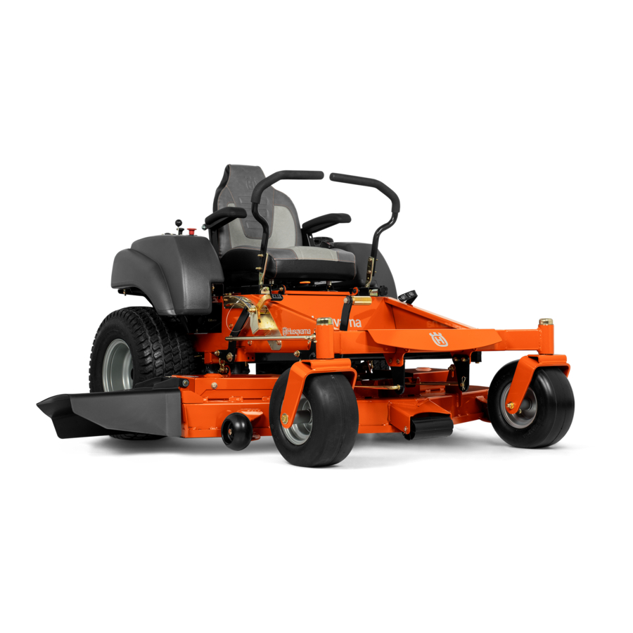
- Page 1 Operator Manual MZ6128 / 966502301 Please read the operator’s manual carefully and make sure you understand the instructions before using the machine. English...
- Page 2 To implement improvements, specifications and designs can be altered without prior notification. Note that no legal demands can be placed based on the information contained in these instructions. Use only original parts for repairs. The use of other parts voids the warranty. Do not modify or install non-standard equipment to the unit without consent from the manufacturer.
-
Page 3: Table Of Contents
INTRoDUCTIoN ...5 Driving and Transport on Public Roads ...5 Towing ...5 operating ...5 Good Service ...6 Manufacturing Number ...6 SYMBoLS AND DECALS ...7 SAFETY ...9 Safety Instructions ...9 Personal Safety Equipment ...11 Slope operation ...11 Safe Handling of Gasoline ...13 General Maintenance ...14 Transport ...16 Towing ...16... - Page 4 WARNING! Failure to follow cautious operating practices can result in serious injury to the operator or other persons. The owner must understand these instructions, and must allow only trained persons who understand these instructions to operate the mower. Each person operating the mower must be of sound mind and body and must not be under the influence of any mind altering substance.
-
Page 5: Introduction
Congratulations Thank you for purchasing a Husqvarna ride-on mower. This machine is built for superior efficiency to rapidly mow primarily large areas. A control panel that is easily accessible to the operator and a hydrostatic transmission regulated by steering controls both contribute to the machine’s performance. -
Page 6: Good Service
Good Service Husqvarna’s products are sold only in specialized retail stores with complete service. This ensures that you as a customer receive only the best support and service. Before the product is delivered, the machine has, for example, been inspected and adjusted by your retailer. See the certificate in the Service Journal in this operator’s manual. -
Page 7: Symbols And Decals
These symbols are found on the machine and in the operator’s manual. Study them carefully so that you know what they mean. WARNING! Xxxx xxxxxx xxxxx xxxx xxxxxxxxx xxxxxx xxxxxxxxx. xx xxxxxxxx xxxx xxxxxx. Used in this publication to notify the reader of a risk of personal injury or death, particularly if the reader should neglect to follow instructions given in the manual. - Page 8 Read Shut off engine and operator’s remove key before Manual performing any maintenance or repair work Whole body Severing of fingers exposure to and toes thrown objects Moving sharp blades under cover symbOls aND DeCals Keep a safe distance from the machine Do not open or remove safety...
-
Page 9: Safety
Safety Instructions These instructions are for your safety. Read them carefully. WARNING! This symbol means that important safety instructions need to be emphasized. It concerns your safety. IMPORTANT: THIS CUTTING MACHINE IS CAPABLE oF AMPUTATING HANDS AND FEET AND THRoWING oBJECTS. - Page 10 • Watch for traffic when operating near or crossing roadways. • Use extra care when loading or unloading the machine into a trailer or truck. • Always wear eye protection when operating machine. • Data indicates that operators age 60 years and above are involved in a large percentage of riding mower-related injuries.
-
Page 11: Personal Safety Equipment
Personal Safety Equipment WARNING! When using the machine, approved personal protective equipment (shown in illustrations) shall be used. Personal protective equipment cannot eliminate the risk of injury but it will reduce the degree of injury if an accident does happen. Ask your retailer for help in choosing the right equipment. - Page 12 Children Tragic accidents can occur if the operator is not alert to the presence of children. Children are often attracted to the machine and the mowing activity. Never assume that children will remain out of the path of danger. • Keep children out of the mowing area and in the watchful care of a responsible adult other than the operator.
-
Page 13: Safe Handling Of Gasoline
WARNING! The engine must not be started when the driver’s floor plate or any protective plate for the mower deck’s drive belt is removed. Safe Handling of Gasoline To avoid personal injury or property damage, use extreme care in handling gasoline. Gasoline is extremely flammable and the vapors are explosive. -
Page 14: General Maintenance
General Maintenance • Never operate machine in a closed area. • Keep all nuts and bolts tight to be sure the equipment is in safe working condition. • Never tamper with safety devices. Check their proper operation regularly. • Keep machine free of grass, leaves, or other debris buildup. - Page 15 Sparking can occur when working with the battery and the heavy cables of the starter circuit. This can cause battery explosion, fire or eye injury. Sparking in this circuit can not occur after the chassis cable (normally negative, black) is removed from the battery. •...
-
Page 16: Transport
Follow the manufacturer’s recommendation for weight limits for towed equipment. Do not tow near ditches, canals, and other hazards. Spark Arrestor A spark arrestor for the muffler is available through your authorized Husqvarna dealer. saFeTy WARNING! Escaping hydraulic oil under pressure can have sufficient force to penetrate the skin, causing serious injury. -
Page 17: Controls
This operator’s manual describes the Husqvarna Zero Turn Rider. The rider is fitted with a Briggs & Stratton four-stroke overhead valve engine developing 28 horse power*. Control Locations Motion control levers Parking brake Tracking knob Fuel tank Hydro release levers *The power rating of the engines indicated is the average net power output (at specified rpm) of a typical production engine for the engine model measured to SAE standard J1349/ISO1585. -
Page 18: Motion Control Levers
Motion Control Levers The machine’s speed and direction are continuously variable using the two steering controls. The steering controls can be moved forward or backward about a neutral position. Furthermore, there is a neutral position, which is locked if the steering controls are moved outward. -
Page 19: Hour Meter
Hour Meter The hour meter displays the total operating time. It will flash CHG oIL (Change oil) at 50 hour intervals. The flash duration is one hour before and one hour after the interval. The CHG oIL icon will come on and shut off automatically. -
Page 20: Parking Brake
Parking Brake The parking brake is found on the left of the machine. Pull the lever backward to activate the brake and push forward to release it. IMPORTANT INFORMATION The machine must stand absolutely still when applying the parking brake. Always set the parking brake before dismounting. -
Page 21: Fuses
Release the key to the RUN position when the engine has started. For using “accessory”, turn the key counter clockwise. Fuses Fuses are located on the left hand side of the machine. They are accessed by tilting the seat forward. Fuses are flat pin fuses type as used in automobiles. -
Page 22: Cutting Height Adjuster
Cutting Height Adjuster The desired cutting height is set with the height pin. The cutting height pedal releases the deck lift to place the deck and the selected height. For transport, push the lift pedal fully forward until the deck lift latches in the transport (highest) position. Seat Adjustment Lever The seat can be adjusted lengthways. -
Page 23: Refueling
Refueling Read the safety instructions before refueling. The capacity for the tank is 5 gallons (19 liters). Regularly check the gas cap gasket for damage and keep the cap properly tightened. The engine will run on a minimum of 87-octane unleaded gasoline (no oil mix). -
Page 24: Operation
Read the Safety Instructions section and the following pages if you are unfamiliar with the machine. Training Zero turn mowers are far more maneuverable than typical riding mowers due to their unique steering capabilities. We suggest that this section be reviewed in its entirety prior to attempting to move the mower under its own power. -
Page 25: Before Starting
Before Starting • Read the sections Safety Instructions and Controls before starting the machine. • Perform the daily maintenance before starting (see maintenance schedule in the Maintenance section). • Check that there is sufficient fuel in the fuel tank. • Adjust the seat to the desired position. - Page 26 Disengage the mower blades by depressing the blade switch. Move the steering controls outward to the locked (outer) neutral position. Move the throttle to the middle position. OPeRaTION Press the control for disengaging the mower deck Place controls in neutral position Set the throttle 8058-043 80661-012...
- Page 27 open the fuel tank valve. WARNING! Engine exhaust and certain vehicle components contain or emit chemicals considered to cause cancer, birth defects or other reproductive system damage. The engine exhaust contains carbon monoxide, which is an odorless, colorless, poisonous gas. Do not use the machine in enclosed spaces.
-
Page 28: Jumper Cables
Weak Battery WARNING! Lead-acid batteries generate explosive gases. Keep sparks, flame and smoking materials away from batteries. Always wear eye protection when around batteries. IMPORTANT INFORMATION The mower is equipped with a 12-volt negative grounded system. The other vehicle must also be a 12-volt negative grounded system. -
Page 29: Running
Running Release the parking brake by moving the lever downward. NoTE: The mower is equipped with an operator presence system. When the engine is running, any attempt by the operator to leave the seat without first setting the parking brake will shut off the engine. -
Page 30: Operating On Hills
Operating on Hills Read the Safety Instructions Driving on Slopes in the Safety Instructions. WARNING! Do not drive up or down hills with slopes greater than 10 degrees. Do not drive across slopes. • The slowest speed possible should be used before starting up or down hills. -
Page 31: Stopping The Engine
Stopping the Engine Move the throttle to the minimum position (tortoise symbol). If the engine has been worked hard, allow it to idle at least 60 seconds to attain a normal operating temperature before stopping. To prevent fouling the spark plugs, avoid idling the engine for longer periods. -
Page 32: Mowing Tips
Mowing Tips • observe and flag rocks and other fixed objects to avoid collisions. • Begin with a high cutting height and reduce it until the desired mowing result is attained. The average lawn should be cut to 2½" (64 mm) during the cool season and over 3"... -
Page 33: Manual Transport
Manual Transport WARNING! No adjustments or maintenance should be carried out unless: • the engine stopped • the ignition key removed • the parking brake activated When pushing or pulling the mower, engage the IZT (Integrated Zeroturn Transaxle) bypass linkages. The linkages are located on each side of the rear of the unit below the rear engine plate. -
Page 34: Maintenance
MAINTENANCE Check the parking brake Check the engine’s oil level (every refueling) Check the safety system Check for fuel and oil leakages Check/clean the engine’s cooling air intake Check the mower deck Check for loose hardware (screws, nuts) Clean under the mower deck Start the engine and blades, listen for unusual sounds Check for damage Thoroughly clean around the engine... - Page 35 MAINTENANCE Check/adjust throttle cable Check the condition of belts, belt pulleys Change the engine oil Replace the engine oil filter Clean/replace the spark plugs Replace the fuel filter Replace air filter (paper filter) Check the caster wheels (every 200 hours) Replace the air cleaner’s pre-filter Check the hydraulic oil in the oil tank Change the hydraulic oil (every 500 hours)
-
Page 36: Battery
Battery Your mower is equipped with a maintenance free battery and does not need servicing. However, periodic charging of the battery with an automotive type battery charger will extend its life. • Keep battery and terminals clean. • Keep battery bolts tight. •... -
Page 37: Safety System
Safety System This machine is equipped with a safety system that prevents starting or driving under the following conditions. The engine can only be started when: The mower deck is disengaged. The steering controls are in the outer, locked neutral position. The parking brake is on. -
Page 38: Deck Belt
Deck Belt Deck Belt Removal Park on a level surface. Apply park brake.Lower the deck into the lowest cutting position. Remove foot plate and belt shields. Using a ratchet or breaker bar with a on the spring idler bolt, relieve the tension on the belt. -
Page 39: Pump Belt
Pump Belt The belts are not adjustable. Replace belts if they begin to slip from wear. Replacing Pump Belt Park the mower on a level surface. Engage the parking brake. Belt Removal From the top side of the deck: Remove the deck belt (see in this section of the manual). -
Page 40: Cutting Blades
Install and tighten blade bolt securely. Torque blade bolt to 45-55 ft-lbs (60-75 Nm). IMPORTANT INFORMATION Special blade bolt is heat treated. Replace with a Husqvarna bolt if required. Do not use lower grade hardware than specified. WARNING! Before performing any service or adjustment checklist: 1. -
Page 41: Adjusting The Mower Deck
Adjusting the Mower Deck Check the tire pressure before adjustment of the mower deck. See Tire Pressures in Maintenance section. Faulty mower deck adjustments will cause an uneven mowing result. Leveling deck Adjust the deck while the mower is on a level surface. -
Page 42: Anti-Scalp Rollers
Anti-scalp rollers Anti-scalp rollers are properly adjusted when they are just slightly off of the ground when the deck is at the desired cutting height in the operating position. Anti- scalp rollers then keep the deck in the proper position to help prevent scalping in most terrain conditions. -
Page 43: Caster Wheels
Caster Wheels Check every 200 hours. Check that wheels rotate freely. IMPORTANT INFORMATION DO NOT add any type of tire liner or foam fill material to the tires. Excessive loads created by foam tires wil caues premature failures. Use only O.E.M. specified tires. Removal and Installation Remove nut and caster bolt. -
Page 44: Lubrication
Lubrication Schedule 12/12 Every year 1/52 Every Week 1/365 Every day Change hydraulic drive filters. p See Engine Manufacturer's manual General Remove the ignition key to prevent unintentional movements during lubrication. When lubricating with an oil can, it must be filled with engine oil. -
Page 45: Wheel And Deck Zerks
lUbRICaTION Wheel and Deck Zerks Use only good quality bearing grease. Grease from well-known brand names (petrochemical companies, etc.) usually maintains a good quality. Front Wheel Mount Lubricate with a grease gun until the grease is forced out. Front Wheel Bearings Lubricate 3-4 strokes with a grease gun on each set of wheel bearings. -
Page 46: Transaxle (Transmission) Fluid Change
Transaxle (Transmission) Fluid Change This transaxle is designed with an external filter for ease of maintenance. To ensure constant fluid quality levels and longer life, an oil filter change interval of every 200 hours is recommended. The following procedure is performed with the transaxles installed in the mower and the mower on level ground. -
Page 47: Purging Procedures
Purging Procedures Due to the effects air has on efficiency in hydrostatic drive applications, it is critical to purge the system. These purge procedures should be implemented any time a hydrostatic system has been opened to facilitate maintenance or any additional oil has been added to the system. -
Page 48: Troubleshooting Guide
TROUbleshOOTINg gUIDe Problem Engine will not start. Starter does not turn the engine over. Engine runs rough. Engine seems weak. Cause • Blade switch is engaged. • Steering controls are not locked in the neutral position. • Parking brake is not activated. •... - Page 49 TROUbleshOOTINg gUIDe Problem Machine vibrates. Engine overheats. Battery not charging. Machine moves slowly, unevenly, or not at all. Mower deck not engaging. Hydraulic drive leaks oil. Uneven mowing results. Cause • Blades are loose. • Blades are incorrectly balanced. • Engine is loose.
-
Page 50: Storage
Service When ordering spare parts, please specify the purchase year, model, type, and serial number. Always use genuine Husqvarna spare parts. An annual check-up at an authorized service workshop is a good way to ensure that the machine performs its best the following season. -
Page 51: Wiring Diagrams
WIRINg DIagRam... -
Page 52: Technical Data
Engine Manufacturer Type Power Lubrication Fuel Fuel tanks capacity Cooling Alternator Starter Transmission Transmission Speed and direction controls Speed forward Speed reverse Brakes Front caster tires, smooth tread Rear tires, turf pneumatic Tire pressures Frame Cutting Width Cutting Height Uncut Circle Number of Blades Blade Length Nose Roller... -
Page 53: Torque Specifications
The torque values shown should be used as a general guideline when specific torque values are not given. Grade SAE Grade 5 ft./lbs ft./lbs ¼ ½ ¾ ** Grade 5 - Minimum commercial quality (lower quality not recommended) Grade Grade 8.8 ft./lbs ft./lbs 13.5... -
Page 54: Conformity Certificates
CONFORmITy CeRTIFICaTes USA requirements Labels are placed on the engine and/or in the engine compartment stating that the machine will fulfill the requirements. This is also applicable to special requirements for any of the states, (California emission rules etc.). Do not remove any of these labels. Certificates can also be supplied with the machine at delivery or written in the Engine manual. -
Page 55: Service Journal
Action Delivery Service Charge the battery. Adjust the tire pressure of all wheels to 15 PSI (1 bar). Mount the steering controls in the normal position. Connect the contact box to the cable for the seat’s safety switch. Check that the right amount of oil is in the engine. Adjust the position of the steering controls. - Page 56 Action After 10 hours 1. Change the engine oil. 2. Change the oil filter. 3. Check hydraulic oil level. 4. Inspect hydraulic hoses. 5. Inspect hydraulic belt 6. Inspect hydraulic filter. 7. Check neutral position. 8. Check safety system. 9. Check seat belt. 10.
- Page 57 Action Daily Service 1. Clean debris from mower. 2. Check engine oil level. 3. Check the tire pressures. 4. Check underside of deck. 5. Inspect deck pulleys. 6. Check/clean the engine’s cooling air intake. 7. Check safety system. 8. Check seat belt. 9.
- Page 58 seRVICe JOURNal Action Date, mtr reading, stamp, sign 25-Hour Service 1. Check the fuel pump’s air filter. 2. Sharpen/Replace mower blades if required. 3. Check the tire pressures. 4. Check battery with cables. 5. Lubricate according to lubrication chart. 6. Check/clean the engine’s cooling air intake. 7.
-
Page 59: Hour Service
Action 100-Hour Service 1. Grease fittings (caster pivots and caster wheels) 2. Inspect dampeners 3. Inspect frame 4. Inspect throttle cable 5. Inspect hardware 6. Check the tire pressures 7. Change the engine oil and filter 8. Change air filter 9. - Page 60 Action 300-Hour Service 1. Grease fittings (caster pivots and caster wheels) 2. Inspect dampeners 3. Inspect frame 4. Inspect throttle cable 5. Inspect hardware 6. Check the tire pressures 7. Change the engine oil and filter 8. Change air filter 9.
- Page 61 seRVICe JOURNal Action Date, mtr reading, stamp, sign At least once each year 1. Clean the engine’s cooling air intake. 2. Replace the air cleaner’s pre-filter (foam). 3. Replace the air filter’s paper cartridge. 4. Change the engine oil. 5. Replace the engine oil filter 6.
- Page 64 P/N 115 312526R1 10/21/09...