Napoleon LHD45N Installation And Operating Instructions Manual
Hide thumbs
Also See for LHD45N:
- Installation and operating instructions manual (120 pages) ,
- Installation and operating instructions manual (112 pages) ,
- Installation and operating instructions manual (120 pages)
Table of Contents
Advertisement
INSTALLER: LEAVE THIS MANUAL WITH THE APPLIANCE.
CONSUMER: RETAIN THIS MANUAL FOR FUTURE REFERENCE.
NEVER LEAVE CHILDREN OR OTHER AT RISK INDIVIDUALS ALONE WITH THE APPLIANCE
CERTIFIED UNDER CANADIAN AND AMERICAN NATIONAL STANDARDS: ANSI Z21.50 ● CSA 2.22 FOR VENTED GAS FIREPLACES.
CERTIFIED FOR CANADA AND UNITED STATES USING ANSI/CSA METHODS.
SAFETY INFORMATION
WARNING
!
CERTIFIED FOR CANADA AND UNITED STATES USING ANSI/CSA METHODS.
If the information in these instructions
are not followed exactly, a fi re or
explosion may result causing property
damage, personal injury or loss of life.
- Do not store or use gasoline or other fl ammable
vapors and liquids in the vicinity of this or any
other appliance.
- WHAT TO DO IF YOU SMELL GAS:
•
Do not try to light any appliance.
•
Do not touch any electrical switch; do not use
any phone in your building.
•
Immediately call your gas supplier from a
neighbour's phone. Follow the gas supplier's
instructions.
•
If you cannot reach your gas supplier, call the
fi re department.
- Installation and service must be performed by a
qualifi ed installer, service agency or the supplier.
This appliance may be installed in an aftermarket,
permanently located, manufactured home (USA
only) or mobile home, where not prohibited by
local codes.
This appliance is only for use with the type of gas
indicated on the rating plate. This appliance is
not convertible for use with other gases, unless a
certifi ed kit is used.
Phone (705)721-1212 • Fax (705)722-6031 • www.napoleonfi replaces.com • ask@napoleonproducts.com
$10.00
OPERATING INSTRUCTIONS
Wolf Steel Ltd., 24 Napoleon Rd., Barrie, ON, L4M 0G8 Canada /
103 Miller Drive, Crittenden, Kentucky, USA, 41030
INSTALLATION AND
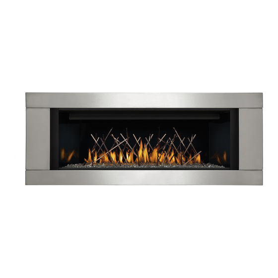
LHD45N
NATURAL GAS
LHD45P
S H O
W N
W I T
WARNING
!
PROPANE
H O
P T I
O N
A L
S U R
R O
U N D
HOT GLASS WILL CAUSE
BURNS.
DO NOT TOUCH GLASS UNTIL
COOLED.
NEVER ALLOW CHILDREN TO
TOUCH GLASS.
1.28C
W415-0834 / C / 02.03.12
1
Advertisement
Table of Contents

Related Manuals for Napoleon LHD45N


Summary of Contents for Napoleon LHD45N
-
Page 1: Safety Information
NEVER LEAVE CHILDREN OR OTHER AT RISK INDIVIDUALS ALONE WITH THE APPLIANCE INSTALLATION AND OPERATING INSTRUCTIONS CERTIFIED UNDER CANADIAN AND AMERICAN NATIONAL STANDARDS: ANSI Z21.50 ● CSA 2.22 FOR VENTED GAS FIREPLACES. LHD45N NATURAL GAS CERTIFIED FOR CANADA AND UNITED STATES USING ANSI/CSA METHODS. SAFETY INFORMATION... -
Page 2: Table Of Contents
TABLE OF CONTENTS INSTALLATION OVERVIEW INTRODUCTION DIMENSIONS GENERAL INSTRUCTIONS GENERAL INFORMATION RATING PLATE INFORMATION VENTING VENTING LENGTHS AND COMPONENTS FOR DIRECT VENT INSTALLATIONS TYPICAL VENT INSTALLATIONS SPECIAL VENT INSTALLATIONS 3.3.1 PERISCOPE TERMINATION 3.3.2 CORNER TERMINATION VENT TERMINAL CLEARANCES VENT APPLICATION FLOW CHART DEFINITIONS ELBOW VENT LENGTH VALUES HORIZONTAL TERMINATION... -
Page 3: Installation Overview
1.0 INSTALLATION OVERVIEW Mantel, see Enclosures, see the section “MINIMUM “MINIMUM CLEARANCES TO COMBUSTIBLE MANTEL ENCLOSURES” section for drywall (or CLEARANCES” other combustible material). section. Venting, see “VENTING” section. Framing, see “FRAMING” section. Framing, see “FRAMING” section. Enclosures, see the section “MINIMUM CLEARANCE TO COMBUSTIBLE... -
Page 4: Introduction
2.0 INTRODUCTION WARNING • THIS APPLIANCE IS HOT WHEN OPERATED AND CAN CAUSE SEVERE BURNS IF CONTACTED. • ANY CHANGES OR ALTERATIONS TO THIS APPLIANCE OR ITS CONTROLS CAN BE DANGEROUS AND IS PROHIBITED. • Do not operate appliance before reading and understanding operating instructions. Failure to operate appliance according to operating instructions could cause fi... -
Page 5: Dimensions
DIMENSIONS ” ” 40 13/16” 39 3/16” ” ” 37 13/16” ” INLET 4 3/4” 7 ½” ELECTRICAL 42” INLET ON 1 3/8” LEFT SIDE 34 1/16” 7” 19 7/8” 4” 1” 18 7/8” 46 1/4” W415-0834 / C / 02.03.12... -
Page 6: General Instructions
GENERAL INSTRUCTIONS WARNING ALWAYS LIGHT THE PILOT WHETHER FOR THE FIRST TIME OR IF THE GAS SUPPLY HAS RUN OUT, WITH THE GLASS DOOR OPENED OR REMOVED. PROVIDE ADEQUATE CLEARANCE FOR SERVICING AND OPERATING THE APPLIANCE. PROVIDE ADEQUATE VENTILATION. NEVER OBSTRUCT THE FRONT OPENING OF THE APPLIANCE. OBJECTS PLACED IN FRONT OF THE APPLIANCE MUST BE KEPT A MINIMUM OF 48”... -
Page 7: General Information
GENERAL INFORMATION FOR YOUR SATISFACTION, THIS APPLIANCE HAS BEEN TEST-FIRED TO ASSURE ITS OPERATION AND QUALITY! APPLIANCE Altitude (FT) 0-4,500 0-4500 Max. Input (BTU/HR) 24,000 24,000 Max. Output Steady State (BTU/HR) 17,280 17,280 Effi ciency (w/the fan on) Min. Inlet Gas Supply Pressure 4.5"... -
Page 8: Rating Plate Information
DE TELS RÈGLEMENTS, SELO DE TELS RÈGLEMENTS, SEL VIGUER. 9700539 (WSL) 4001657 (NGZ) 4001657 (NGZ) 4001657 (NGZ) 4001658 (NAC) 4001659 (WUSA) 4001659 (WUSA) 4001659 (WUSA) LHD45N CLHD45N MODEL MODEL MODEL CLHD45P LHD45P 0-4500FT (0-1370m) ALTITUDE / ÉLÉVATION TITUDE / ÉLÉVATION TITUDE / ÉLÉVATION... -
Page 9: Venting Lengths And Components For Direct Vent Installations
VENTING LENGTHS AND COMPONENTS FOR DIRECT VENT INSTALLATIONS NOTE: There MUST be a 25% reduction in total horizontal length (H ) when using fl ex vent. Use only Wolf Steel, Simpson Dura-Vent, Selkirk Direct Temp, American Metal Amerivent or Metal-Fab venting components. -
Page 10: Typical Vent Installations
TYPICAL VENT INSTALLATIONS NOTE: There MUST be a 25% reduction in total horizontal length (H ) when using fl ex vent. 16” MINIMUM 40 FEET 18” MAXIMUM MAXIMUM (FLEX VENT) 24” MAXIMUM 3 FEET (RIGID VENT) MINIMUM 8” MINIMUM 45 13/16” MINIMUM PLUS 37 13/16”... -
Page 11: Special Vent Installations
SPECIAL VENT INSTALLATIONS 3.3.1 PERISCOPE TERMINATION Use the periscope kit to locate the air termination above grade. The periscope must be installed so that when fi nal grading is completed, the bottom air slot is located a minimum 12” above grade. The maximum allowable vent length is 10’ for a 12”... -
Page 12: Vent Terminal Clearances
VENT TERMINAL CLEARANCES COVERED BALCONY APPLICATIONS ††* = 3 feet = 2 x ACTUAL INSTALLATIONS feet CANADA U.S.A. 12” 12” Clearance above grade, veranda porch, deck or balcony. 12” 9” Clearance to windows or doors that open. Δ Δ 12” * 12”... -
Page 13: Vent Application Flow Chart
VENT APPLICATION FLOW CHART Horizontal Termination Vertical Termination Vertical rise is equal Vertical rise is equal Vertical rise is less Vertical rise is less to or greater than to or greater than than horizontal run than horizontal run the horizontal run the horizontal run Horizontal run + Horizontal run +... -
Page 14: Horizontal Termination
HORIZONTAL TERMINATION NOTE: There MUST be a 25% reduction in total horizontal length (H ) when using fl ex vent. ) < (V See graph to determine the required vertical Simple venting confi guration (only one 90° elbow) rise V for the required horizontal run H REQUIRED VERTICAL... - Page 15 NOTE: There MUST be a 25% reduction in total horizontal length (H ) when using fl ex vent. ) > (V Simple venting configuration (only one 90° elbow) See graph to determine the required vertical rise V for the required horizontal run H 147”...
-
Page 16: Vertical Termination
VERTICAL TERMINATION NOTE: There MUST be a 25% reduction in total horizontal length (H ) when using fl ex vent. ) < (V Simple venting configurations. See graph to determine the required vertical rise V for the required horizontal run H REQUIRED VERTICAL RISE IN... - Page 17 NOTE: There MUST be a 25% reduction in total horizontal length (H ) when using fl ex vent. ) > (V Simple venting configurations. See graph to determine the required vertical rise V for the required horizontal run H REQUIRED VERTICAL RISE IN FEET V...
-
Page 18: Vertical Through Existing Chimney
3.10 VERTICAL THROUGH EXISTING CHIMNEY WARNING RISK OF FIRE! CO-AXIAL TO CO-LINEAR VENTING CONFIGURATIONS MUST ONLY BE USED IN A NON- COMBUSTIBLE CHIMNEY OR ENCLOSURE. INSTALLATION IN A COMBUSTIBLE ENCLOSURE COULD RESULT IN A FIRE. This appliance is designed to be attached to a 3” co-linear aluminum fl ex vent system running the full length of a masonry chimney. -
Page 19: Vent Heat Shield Installation
3.11 VENT HEAT SHIELD INSTALLATION For shipping purposes, the heat shield has been attached on top of the appliance. If venting with a 90 degree elbow directly off of the top of the appliance, the elbow heat shield must be reposi- tioned and secured with the two screws (supplied) as illustrated. -
Page 20: Horizontal Installation
4.1.1 HORIZONTAL INSTALLATION WARNING THE FIRESTOP ASSEMBLY MUST BE INSTALLED WITH THE VENT SHIELD TO THE TOP. TERMINALS MUST NOT BE RECESSED INTO A WALL OR SIDING MORE THAN THE DEPTH OF THE RETURN FLANGE OF THE MOUNTING PLATE. This application occurs when venting through an exterior wall. Having determined the correct height for the air terminal VENT location, cut and frame a hole in the exterior wall as... -
Page 21: Using Rigid Vent Components
USING RIGID VENT COMPONENTS The vent system must be supported approximately every 3 feet for both vertical and horizontal runs. Use Wolf Steel Ltd. support ring assembly or equivalent noncombustible strapping to maintain the minimum clearance to combustibles for both vertical and horizontal runs. All inner exhaust and outer intake vent pipe joints may be sealed using either red high temperature silicone sealant W573-0002 (not supplied) or black high temperature sealant W573-0007 Mill Pac (not supplied) with the exception of the appliance exhaust fl... -
Page 22: Extended Horizontal And Corner Terminal Installation
EXTENDED HORIZONTAL AND CORNER TERMINAL INSTALLATION A. Follow the instructions for "HORIZONTAL AIR TERMINAL INSTALLATIONS" section. AIR TERMINAL TELESCOPIC Continue adding components alternating inner rigid pipe and outer rigid pipe. Ensure SLEEVE that all inner rigid pipe and elbows have sufficient vent spacers attached and each component is sealed and securely fastened to the one prior. -
Page 23: Using Flexible Venting
USING FLEXIBLE VENTING NOTE: All vent parameters are stated for rigid venting. If using approved Wolf Steel Ltd. fl exible vent- ing then total horizontal lengths (H ) are reduced by 25%. MOBILE HOME INSTALLATION This appliance is certifi ed to be installed as an OEM (Original Equipment Manufacturer) installation in a manufactured home or mobile home and must be installed in accordance with the manufacturer’s instructions and the Manufactured Home Construction and Safety Standard, Title 24 CFR, Part 3280, in the United States or the Mobile Home Standard, CAN/CSA Z240 MH Series, in Canada. -
Page 24: Gas Installation
GAS INSTALLATION WARNING RISK OF FIRE, EXPLOSION OR ASPHYXIATION. ENSURE THERE ARE NO IGNITION SOURCES SUCH AS SPARKS OR OPEN FLAMES. SUPPORT GAS CONTROL WHEN ATTACHING GAS SUPPLY PIPE TO PREVENT DAMAGING GAS LINE. ALWAYS LIGHT THE PILOT WHETHER FOR THE FIRST TIME OR IF THE GAS SUPPLY HAS RUN OUT WITH THE GLASS DOOR OPENED OR REMOVED. -
Page 25: Framing
5.0 FRAMING WARNING RISK OF FIRE! IN ORDER TO AVOID THE POSSIBILITY OF EXPOSED INSULATION OR VAPOUR BARRIER COMING IN CONTACT WITH THE APPLIANCE BODY, IT IS RECOMMENDED THAT THE WALLS OF THE APPLIANCE ENCLOSURE BE “FINISHED” (IE: DRYWALL / SHEETROCK), AS YOU WOULD FINISH ANY OTHER OUTSIDE WALL OF A HOME. - Page 26 WARNING DO NOT BUILD INTO THIS AREA - IT MUST BE LEFT CLEAR TO PROVIDE ADEQUATE CLEARANCE FOR THE VENT IN THIS 14” WIDE AREA CENTERED ALONG THE FRONT OF THE FIREPLACE. NO COMBUSTIBLES ARE ALLOWED. FIREPLACE SHOULD BE IN ITS FINAL LOCATION BEFORE FRAMING.
- Page 27 MAINTAIN THESE MINIMUM CLEARANCES TO COMBUSTIBLES FROM FRAMING APPLIANCE AND VENT SURFACES: ROUGH OPENING HEIGHT WIDTH DEPTH TO CEILING TO CEILING SIDE TO COMBUSTIBLE SIDES AND REAR & SIDE FROM BASE FROM TOP WALL FINISHING ABOVE BOTTOM STANDOFFS APPLIANCE VENT OF VENT APPLIANCE APPLIANCE...
-
Page 28: Minimum Clearance To Combustible Enclosures
MINIMUM CLEARANCE TO COMBUSTIBLE ENCLOSURES IMPORTANT: The LHD45 requires a minimum inside enclosure height of 56”, measured from the bottom of the appliance. For temperature requirements, this area must be left unobstructed. It is recommended that the enclosure be ventilated at the top and bottom to circulate the hot air. NON-COMBUSTIBLE COMBUSTIBLE SHELF... - Page 29 NON-COMBUSTIBLE 30 ¹¹/ ” 14” TOP OF APPLIANCE OPENING 2” 42” 46 ¼” COMBUSTIBLE Finishing material may be secured directly to the appliance body where practical. W415-0834 / C / 02.03.12...
-
Page 30: Alcove Enclosure
ALCOVE ENCLOSURE RECESS OR ALCOVE AREA ENCLOSURE AREA APPLIANCE NOTE: Recesses or alcoves above the appliance can be made as deep as desired provided the minimum clearances to combustibles are maintained. Non-combustible material can be used, provided the minimum clearances to combustible materials are applied. -
Page 31: Minimum Mantel Clearances
MINIMUM MANTEL CLEARANCES WARNING RISK OF FIRE, MAINTAIN ALL SPECIFIED AIR SPACE CLEARANCES TO COMBUSTIBLES. FAILURE TO COMPLY WITH THESE INSTRUCTIONS MAY CAUSE A FIRE OR CAUSE THE APPLIANCE TO OVERHEAT. ENSURE ALL CLEARANCES (I.E. BACK, SIDE, TOP, VENT, MANTEL, FRONT, ETC.) ARE CLEARLY MAINTAINED. -
Page 32: Finishing
6.0 FINISHING WARNING RISK OF FIRE! NEVER OBSTRUCT THE FRONT OPENING OF THE APPLIANCE. THE FRONT OF THE APPLIANCE MUST BE FINISHED WITH ANY NON-COMBUSTIBLE MATERIALS SUCH AS BRICK, MARBLE, GRANITE, ETC., PROVIDED THAT THESE MATERIALS DO NOT GO BELOW THE SPECIFIED DIMENSION AS ILLUSTRATED. DO NOT STRIKE, SLAM OR SCRATCH GLASS. -
Page 33: Logo Placement
LOGO PLACEMENT 1” 2 ¾” TRIM INSTALLATION Place trim as shown into the slots of the right and left brackets behind the access panel. LEFT BRACKET SHOWN W415-0834 / C / 02.03.12... -
Page 34: Glass Embers
GLASS EMBERS WARNING CLEAN THE GLASS MEDIA PRIOR TO INSTALLATION. BEFORE APPLYING THE CLEANED GLASS, ENSURE THAT IT IS DRY. DO NOT CHANGE OR SUBSTITUTE THE GLASS MEDIA MATERIAL PROVIDED WITH THIS APPLIANCE. IF REPLACING, USE ONLY THE REPLACEMENT GLASS MEDIA AVAILABLE FROM YOUR AUTHORIZED DEALER / DISTRIBUTOR. -
Page 35: Optional Blower Installation
7.0 OPTIONAL BLOWER INSTALLATION WARNING RISK OF FIRE AND ELECTRICAL SHOCK. TURN OFF THE GAS AND ELECTRICAL POWER BEFORE SERVICING THIS APPLIANCE. USE ONLY WOLF STEEL APPROVED OPTIONAL ACCESSORIES AND REPLACEMENT PARTS WITH THIS APPLIANCE. USING NON-LISTED ACCESSORIES (BLOWERS, DOORS, LOUVRES, TRIMS, GAS COMPONENTS, VENTING COMPONENTS, ETC.) COULD RESULT IN A SAFETY HAZARD AND WILL VOID THE WARRANTY AND CERTIFICATION. -
Page 36: Valve Train Assembly
7.1.2 VALVE TRAIN ASSEMBLY Remove the door, see “DOOR REMOVAL / INSTALLATION” section. Remove the media tray and burner, see “BURNER REMOVAL” section. Remove the fourteen screws from the valve train assembly. Carefully lift the valve train assembly and turn off the manual shut-off valve, see “GAS INSTALLATION”... -
Page 37: Installing The Blower
INSTALLING THE BLOWER INSTALLATION TO BE DONE BY A QUALIFIED INSTALLER and must be electrically connected and grounded in accordance with local codes. In the absence of local codes, use the current CSA C22.1 Canadian electrical code in Canada or the ANSI / NFPA 70 National Electrical Code in the United States The three slots on the blower mounting bracket allow ease of adjustment when attaching the blower. -
Page 38: Electrical Connection
8.0 ELECTRICAL CONNECTION WARNING DO NOT USE THIS APPLIANCE IF ANY PART HAS BEEN UNDER WATER. CALL A QUALIFIED SERVICE TECHNICIAN IMMEDIATELY TO HAVE THE APPLIANCE INSPECTED FOR DAMAGE TO THE ELECTRICAL CIRCUIT. RISK OF ELECTRICAL SHOCK OR EXPLOSION. DO NOT WIRE 110V TO THE VALVE OR TO THE APPLIANCE WALL SWITCH. -
Page 39: Hard Wiring Connection
HARD WIRING CONNECTION It is necessary to hard wire this appliance. Permanently framing the appliance with an enclosure, requires the appliance junction box to be hard wired. This appliance must be electrically connected and grounded in accordance with local codes. In the absence of local codes, use the current CSA C22.1 Canadian electrical code in Canada or the ANSI/NFPA 70-1996 national electrical code in the United States. -
Page 40: Wiring Diagram
WIRING DIAGRAM WARNING DO NOT WIRE 110 VOLTS TO THE VALVE OR WALL SWITCH. This appliance comes equipped with a battery back-up. If this backup is used, install 4 AA batteries (not supplied) into the holder and connect to the wire harness. Place near the IPI board. Connect the battery holder to the wire harness before using the appliance. -
Page 41: Operating Instructions
9.0 OPERATING INSTRUCTIONS When lit for the fi rst time, the appliance will emit a slight odour for a few hours. This is a normal temporary con- dition caused by the “burn-in” of internal paints and lubricants used in the manufacturing process and will not occur again. -
Page 42: Anti Condensation Switch (Optional)
ANTI CONDENSATION SWITCH (OPTIONAL) This appliance has the option to switch from an electronic intermittent pilot ignition (IPI) to a standing pilot (ACS) for cold climates. The anti condensation switch (standing pilot) is located in the center of the control panel. Using your fi nger, fl ip the switch up for standing pilot, or down for intermittent pilot ignition. -
Page 43: Flame Characteristics
10.3 FLAME CHARACTERISTICS It’s important to periodically perform a visual check of the pilot and burner fl ames. Compare them to the illustration provided. If any fl ames appear abnormal call a service person. PILOT BURNER ELECTRODE FLAME SENSOR FLAME MUST ENVELOP UPPER 3/8”... -
Page 44: Maintenance
11.0 MAINTENANCE MAINTENANCE MAINTENANCE WARNING MAINTENANCE TURN OFF THE GAS AND ELECTRICAL POWER BEFORE SERVICING THE APPLIANCE. APPLIANCE MAY BE HOT, DO NOT SERVICE UNTIL APPLIANCE HAS COOLED. DO NOT USE ABRASIVE CLEANERS. CAUTION: Label all wires prior to disconnection when servicing controls. Wiring errors can cause improper and dangerous operation. -
Page 45: Glass / Door Replacement
11.1 GLASS / DOOR REPLACEMENT WARNING DO NOT USE SUBSTITUTE MATERIALS. GLASS MAY BE HOT, DO NOT TOUCH GLASS UNTIL COOLED. CARE MUST BE TAKEN WHEN REMOVING AND DISPOSING OF ANY BROKEN DOOR GLASS OR DAMAGED COMPONENTS. BE SURE TO VACUUM UP ANY BROKEN GLASS FROM INSIDE THE APPLIANCE BEFORE OPERATION. -
Page 46: Care Of Plated Parts
11.3 CARE OF PLATED PARTS If the appliance is equipped with plated parts, you must clean fi ngerprints or other marks from the plated surfaces before operating the appliance for the fi rst time. Use a glass cleaner or vinegar and towel to clean. If not cleaned properly before operating for the fi... -
Page 47: Replacements
12.0 REPLACEMENTS Contact your dealer or the factory for questions concerning prices and policies on replacement parts. Normally all parts can be ordered through your Authorized dealer / distributor. FOR WARRANTY REPLACEMENT PARTS, A PHOTOCOPY OF THE ORIGINAL INVOICE WILL BE REQUIRED TO HONOUR THE CLAIM. - Page 48 TERMINAL KITS PART NO. DESCRIPTION GD-201 PERISCOPE GD-222 WALL TERMINAL ACCESSORIES PART NO. DESCRIPTION LS45K 4 SIDED SURROUND - BLACK LDS45K DELUXE 4 SIDED SURROUND - BLACK LDS45N DELUXE 4 SIDED SURROUND - BROWN LDS45W DELUXE 4 SIDED SURROUND - WHITE LPS45SS PREMIUM 4 SIDED SURROUND - STAINLESS STEEL LGF45...
- Page 49 W415-0834 / C / 02.03.12...
- Page 50 25 26 W415-0834 / C / 02.03.12...
-
Page 51: Troubleshooting
13.0 TROUBLESHOOTING WARNING ALWAYS LIGHT THE PILOT WHETHER FOR THE FIRST TIME OR IF THE GAS SUPPLY HAS RAN OUT, WITH THE GLASS DOOR OPEN OR REMOVED. TURN OFF THE GAS AND ELECTRICAL POWER BEFORE SERVICING THE APPLIANCE. APPLIANCE MAY BE HOT, DO NOT SERVICE UNTIL APPLIANCE HAS COOLED. DO NOT USE ABRASIVE CLEANERS. - Page 52 SYMPTOM PROBLEM TEST SOLUTION Carbon is being Air shutter has become Ensure air shutter opening is free of lint or other deposited on blocked. obstructions. glass, logs, Flame is impinging on the Check that the glass, logs, rocks or media are rocks, media glass, logs, rocks, media correctly positioned.
- Page 53 SYMPTOM PROBLEM TEST SOLUTION White / grey fi lm Sulphur from fuel is being Clean the glass, see “CARE OF GLASS” section forms. deposited on glass, logs or DO NOT CLEAN GLASS WHEN HOT. combustion chamber If deposits are not cleaned off regularly, the glass surfaces.
-
Page 54: Warranty
14.0 WARRANTY NAPOLEON® products are manufactured under the strict Standard of the world recognized ISO 9001 : 2008 Quality Assurance Certifi cate. NAPOLEON® products are designed with superior components and materials assembled by trained craftsmen who take great pride in their work. The burner and valve assembly are leak and test-fi red at a quality test station. The complete appliance is again thoroughly inspected by a qualifi... -
Page 55: Service History
15.0 SERVICE HISTORY 43.1 W415-0834 / C / 02.03.12... - Page 56 17.0 NOTES 44.1 W415-0834 / C / 02.03.12...