Table of Contents
Advertisement
Advertisement
Table of Contents

Related Manuals for Humminbird ProAngler


Summary of Contents for Humminbird ProAngler
-
Page 2: Installation Preparation
Customer Support section. INSTALLATION OVERVIEW Your Humminbird fishfinder consists of two primary components to install: the control head and the transducer. The control head contains the sonar transmit and receive circuitry, as well as the user controls and display. -
Page 3: Installation Overview
INSTALLATION PREPARATION Determining How to Mount the Transducer Your Humminbird fishfinder includes a standard transducer. This transducer can be mounted on the transom of the boat or bonded to the inside of a fiberglass hull boat. The transom installation, which is the most widely used, places the transducer on the outside of the boat hull. -
Page 4: Alternate Mounting Methods
ALTERNATE MOUNTING METHODS ALTERNATE TRANSDUCERS AND MOUNTING METHODS Your Humminbird fishfinder comes with everything necessary for installation and operation on most boats. However, there are several situations which may require a different type of transducer. Inboard boats, wood or metal hulls, and sail boats create unique transducer mounting needs Alternate transducers and mounting methods are detailed below. -
Page 5: Beginning Installation
BEGINNING INSTALLATION Now that you have determined the transducer mounting method you can begin installation of your new Humminbird fishfinder. The installation guide included on the next few pages provides detailed step by step instructions for installation of the control head and transducer. For transom mount transducer installations you will need the mounting template included with your manual. -
Page 6: Transom Installation
Do not begin this transducer installation until you read the Installation Preparation in the Operation Guide. This chapter contains information critical to the correct installation of your transducer. Due to the wide variety of boat hulls, only general instructions are presented in the installation guide. - Page 7 If the propeller(s) is (are) forward of the transom, it may be impossible to find an area clear from turbulence, and a different mounting technique or transducer type should be considered. Step Two - Drill the Mounting Holes 1. Remove the mounting template from the front of the Operations Manual. 2.
- Page 9 Step Four - Mount the Transducer to the Transom 1. Apply silicone sealant to the mounting holes drilled into the transom. 2. Align the transducer assembly with the drilled holes in the transom (Figure 8). 3. Use either a flat head screwdriver, a 5/16" (8mm) hex driver, or a 5/16" (8mm) socket to mount the assembly.
- Page 10 mounting bracket. Drill this hole and install the screw after final testing and adjustments have been completed.
- Page 11 If the cable is too short, extension cables are available to extend the transducer cable up to a total of 50' (15 m). Call Humminbird Customer Support for more information. Follow these steps to route the cable through the transom: 1.
-
Page 12: Inside The Hull Installation
Inside the hull mounting generally produces good results in single thickness fiberglass-hulled boats. Humminbird cannot guarantee depth performance when transmitting and receiving through the hull of the boat since some signal loss occurs. The amount of loss depends on hull construction and thickness, and the installation. - Page 13 The transducer cannot transmit through air. The water purges any air from between the transducer and the hull and fills any voids in the coarse fiberglass surface.
- Page 14 3. Power up the Control Head. 4. Run the boat at various speeds and water depths while observing the screen on the Control Head. If the unit functions well at low speeds but begins to skip or miss the bottom at higher speeds, the transducer needs to be moved. If depth performance is required, test the fishfinder in water at the desired depth.
-
Page 15: Control Head Installation
CONTROL HEAD INSTALLATION Step One - Determine Where to Mount Begin the installation by determining where to mount the control head. Consider the following to determine best location: The cables for power, transducer and temp/speed accessories (if applicable) should be installed first and must reach the mounting location. Extension cables are available. - Page 16 fuse in the connection. If you must wire the control head directly to a battery, be sure to install an inline fuse holder...
- Page 17 (not included) for the protection of the unit (Figure 21). Humminbird is not responsible for over voltage or over current failures. In order to minimize the potential for interference with other marine electronics a separate power source (such as a second battery) may be necessary.
- Page 18 Optional: If the cables pass outside the mounting bracket, install the hole cover over the hole and fasten in place using the two #8 x 7/8” (22mm) wood screws (Figure 24).
- Page 19 5. Install the control head by sliding it onto the mounting bracket until it is fully seated. To remove the unit simply depress the latch on the rear of the unit and lift (Figure 29). Your Humminbird is now ready for operation. INSTALLATION CONTROL HEAD INSTALLATION...
-
Page 20: Test The Installation
Note: it is often necessary to make several incremental transducer adjustments before optimum high-speed performance is achieved. Important: For Transom Mount transducer installations, install the third mounting screw after the final transducer adjustments. Humminbird 3 Humminbird Lane Eufaula, Alabama 36027... -
Page 21: Available Accessories
Toll-Free number listed on the back cover of this manual. The ProAngler is completely automatic and easy to use. Simply press the POWER button and the unit will locate and track the bottom from 2' to 600' changing ranges as necessary, display any structure or suspended fish and work at speeds from 0 to over 70 mph. - Page 22 Grass, trees, stumps, wrecks or other debris are accurately displayed, however the depiction of these objects varies with boat speed and direction. The best way to learn to interpret structure is to operate the ProAngler over a variety of known conditions and experiment with user functions to best represent those conditions on-screen.
- Page 23 Sonar targets which are not physically attached to the bottom may take one of many shapes. Surface clutter is the layer of water near the surface which is rich in algae and other growth, and often is aerated by wind or wave action.
-
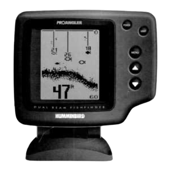
Page 24: Control Functions
CONTROL FUNCTIONS The ProAngler uses a simple 5-button keypad for all user input. When any button is pressed, an audible "chirp" confirms the control input. In the event that a particular button has no function or is inappropriate for the situation, an audible "error", or multiple chirps, will be heard. - Page 25 options, press and hold MENU-the menu will remain on-screen indefinitely. Once you release the menu button, the screen will time out. Once a menu times out, it is still considered the active menu. Pressing MENU will bring up the last used menu. The UP ARROW and DOWN ARROW make adjustments to menu functions.
- Page 26 The ProAngler automatically adjusts the depth range depending on the depth of the water. The unit tries to maintain the bottom depiction about 2/3 down the total range (for example, in 20' of...
- Page 27 UP or DOWN ARROW button. The button press will bring the Depth Range menu on-screen and allows immediate adjustment of the range. To return to "Automatic" Depth Range control, press the MENU button until the Depth Range menu appears on-screen and use the UP ARROW to select AUTO. The ProAngler returns to Automatic operation. Zoom Zoom is similar to Depth Range in that it controls the range of information displayed in the graphics area of the display.
- Page 28 shown on the right side of the display. Zoom can either operate automatically, in which the Zoom range is constantly adjusted to show the bottom, or manually, in which the user controls the location of the Zoom range. When the range is shown in the menu, the upper number represents the top of the current Zoom range.
- Page 29 With this setting, any fish symbol appearing on-screen activates the Fish Alarm. Once the Fish Alarm is enabled, the ProAngler emits an audible beep when the selected size fish symbol appears on-screen. The sound is slightly different for each of the three fish symbol sizes, so with practice, it is possible to distinguish the size of the detected fish without looking at the unit.
- Page 30 Triplog provides seven pieces of information; the current digital depth, water surface temperature, current boat speed, the distance traveled since the ProAngler was powered up or reset, the average speed, the total time elapsed since power-up or reset, and the input voltage from your boat's electrical system.
- Page 31 Further identification shows whether the fish is in the wide or narrow beam. The ProAngler will also attach The depth beneath the surface to the selected fish symbol.
-
Page 32: Using Diagnostic
The final Option is Reset. With so many User Options available to customize the ProAngler, it is easy to configure the unit in such a way that it is detrimental to a particular use. By using the Reset function, all variable or user-controlled features of the ProAngler are returned to the factory settings. - Page 33 Diagnostic while running the boat at high speeds to show the voltage gain. Also, if you are using the ProAngler in portable configuration or from the trolling motor battery, Diagnostic can be used to evaluate the health of the battery by showing the current voltage.