Mitsubishi Electric MSZ-GC22VA Service Manual
Split-type, heat pump air conditioners
Hide thumbs
Also See for MSZ-GC22VA:
- Operating instructions manual (10 pages) ,
- Operating instructions manual (12 pages) ,
- Installation manual (5 pages)
Table of Contents
Advertisement
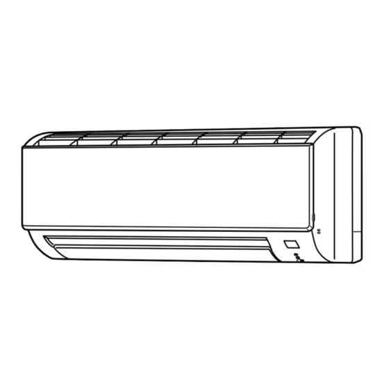
SPLIT-TYPE, HEAT PUMP AIR CONDITIONERS
INDOOR UNIT
SERVICE MANUAL
Wireless type
Models
MSZ-GC22VA -
MSZ-GC22VA -
MSZ-GC25VA -
MSZ-GC25VA -
MSZ-GC35VA -
MSZ-GC35VA -
NOTE:
RoHS compliant products have <G> mark on the spec name plate.
•
E2
Please void OBH468 REVISED EDITION-A.
E1
E2
E1
E2
E1
E2
Outdoor unit service manual
MUZ-GC·VA Series (OBH469)
MXZ-A·VA Series (OB377)
MXZ-8A140A (OC316)
CONTENTS
1. TECHNICAL CHANGES ····································2
2. PART NAMES AND FUNCTIONS······················2
3. SPECIFICATION·················································3
4. NOISE CRITERIA CURVES ·······························4
5. OUTLINES AND DIMENSIONS ·························5
6. WIRING DIAGRAM ············································6
7. REFRIGERANT SYSTEM DIAGRAM ················6
8. SERVICE FUNCTIONS ······································7
9. MICROPROCESSOR CONTROL ······················9
10. TROUBLESHOOTING······································14
11. DISASSEMBLY INSTRUCTIONS·····················26
PARTS CATALOG (OBB468)
has been added.
No. OBH468
REVISED EDITION-B
Advertisement
Table of Contents
Troubleshooting

Related Manuals for Mitsubishi Electric MSZ-GC22VA


Summary of Contents for Mitsubishi Electric MSZ-GC22VA
-
Page 1: Table Of Contents
SPLIT-TYPE, HEAT PUMP AIR CONDITIONERS Please void OBH468 REVISED EDITION-A. INDOOR UNIT No. OBH468 SERVICE MANUAL REVISED EDITION-B Wireless type Models MSZ-GC22VA - MSZ-GC22VA - MSZ-GC25VA - MSZ-GC25VA - MSZ-GC35VA - MSZ-GC35VA - Outdoor unit service manual MUZ-GC·VA Series (OBH469) MXZ-A·VA Series (OB377) -
Page 2: Technical Changes
• 10-6.”ACheck of indoor fan motor” has been corrected. Revision B: • has been added. TECHNICAL CHANGES MSZ-GA22VA - ➔ MSZ-GC22VA - MSZ-GA25VA - ➔ MSZ-GC25VA - MSZ-GA35VA - ➔ MSZ-GC35VA - 1. Indoor model has been changed. MSZ-GC22VA - ➔... -
Page 3: Specification
MSZ-GC22VA MSZ-GC25VA MSZ-GC35VA ACCESSORIES Installation plate Installation plate fixing screw 4 o 25 mm Remote controller holder Fixing screw for 3 3.5 o 1.6 mm (Black) Battery (AAA) for remote controller Wireless remote controller Felt tape (Used for left or left-rear piping) -
Page 4: Noise Criteria Curves
NOISE CRITERIA CURVES MSZ-GC22VA MSZ-GC35VA MSZ-GC25VA FUNCTION SPL(dB(A)) FAN SPEED FUNCTION SPL(dB(A)) LINE FAN SPEED LINE COOLING COOLING Super High Super High HEATING HEATING NC-70 NC-70 NC-60 NC-60 NC-50 NC-50 NC-40 NC-40 NC-30 NC-30 APPROXIMATE APPROXIMATE THRESHOLD OF THRESHOLD OF... -
Page 5: Outlines And Dimensions
OUTLINES AND DIMENSIONS MSZ-GC22VA Unit : mm MSZ-GC25VA MSZ-GC35VA 11 X 26 Oblong hole 11 X 20 Oblong hole Installation plate Indoor unit Air in Wall hole [ 65 Installation plate Piping Drain hose Air out [35 O.D Insulation [6.35 - 0.5 m (Flared connection [6.35) Liquid line [9.52 - 0.43 m (Flared connection [9.52) -
Page 6: Wiring Diagram
WIRING DIAGRAM MSZ-GC22VA MSZ-GC25VA MSZ-GC35VA REFRIGERANT SYSTEM DIAGRAM MSZ-GC22VA Unit : mm MSZ-GC25VA MSZ-GC35VA Refrigerant pipe [9.52 (with heat insulator) Indoor coil Indoor thermistor heat RT12 (main) exchanger Flared connection Indoor coil thermistor RT13 (sub) Room temperature thermistor RT11 Flared connection Refrigerant pipe [6.35... -
Page 7: Service Functions
SERVICE FUNCTIONS MSZ-GC22VA MSZ-GC25VA MSZ-GC35VA 8-1. TIMER SHORT MODE For service, set time can be shortened by short circuit of JPG and JPS on the electronic control P.C. board. The time will be shortened as follows. (Refer to 10-7.) Set time : 1-minute ➔ 1-second Set time : 3-minute ➔... - Page 8 8-3. AUTO RESTART FUNCTION When the indoor unit is controlled with the remote controller, the operation mode, the set temperature, and the fan speed are memorized by the indoor electronic control P.C. board. “AUTO RESTART FUNCTION” automatically starts operation in the same mode just before the shutoff of the main power. Operation If the main power has been cut, the operation settings remain.
-
Page 9: Microprocessor Control
MICROPROCESSOR CONTROL MSZ-GC22VA MSZ-GC25VA MSZ-GC35VA WIRELESS REMOTE CONTROLLER Signal transmitting section Operation display section OPERATE/STOP FAN SPEED CONTROL button (ON/OFF) button OFF TIMER button OPERATION SELECT button ON TIMER button ECONO COOL button TIME SET buttons Open the front lid. - Page 10 9-1. COOL ( ) OPERATION (1) Press OPERATE/STOP(ON/OFF) button. OPERATION INDICATOR lamp of the indoor unit turns on with a beep tone. (2) Select COOL mode with OPERATION SELECT button. (3) Press TEMPERATURE buttons (TOO WARM or TOO COOL button)to select the desired temperature. The setting range is 16 ~ 31°C.
- Page 11 NOTE 2 FOR MULTI SYSTEM AIR CONDITIONER OUTDOOR UNIT : MXZ series Multi system air conditioner can connect two or more indoor units with one outdoor unit. •Unit won’t operate in case the total capacity of indoor units exceeds the capacity of outdoor units. Do not connect indoor units beyond the outdoor unit capacity.
- Page 12 (7) SWING ( ) mode By selecting SWING mode with VANE CONTROL button, the horizontal vane swings vertically. (8) Cold air prevention in HEAT operation The horizontal vane position is set to Upward. NOTE : When 2 or more indoor units are operated with multi outdoor unit, even if any indoor unit turns thermostat off, this control doesn’t work in the indoor unit.
- Page 13 2. To release the timer START To release ON timer, press ON TIMER button ( STOP To release OFF timer, press OFF TIMER button( TIMER is cancelled and the display of set time disappears. PROGRAM TIMER • OFF timer and ON timer can be used in combination. The timer of the set time that is reached first will operate first. •...
-
Page 14: Troubleshooting
TROUBLESHOOTING MSZ-GC22VA MSZ-GC25VA MSZ-GC35VA 10-1. Cautions on troubleshooting 1. Before troubleshooting, check the following: 1) Check the power supply voltage. 2) Check the indoor/outdoor connecting wire for mis-wiring. 2. Take care of the following during servicing 1) Before servicing the air conditioner, be sure to turn OFF the main unit first with the remote controller, and then after confirming the horizontal vane is closed, turn OFF the breaker and / or disconnect the power plug. -
Page 15: Failure Mode Recall Function
10-2. Failure mode recall function Outline of the function This air conditioner can memorize the abnormal condition which has occurred once. Even though LED indication listed on the troubleshooting check table (10-4.) disappears, the memorized failure details can be recalled. This mode is very useful when the unit needs to be repaired for the abnormality which doesn't recur. - Page 16 2. Indoor unit failure mode table Upper lamp of OPERATION Abnormal point Condition Correspondence INDICATOR lamp (Failure mode) Not lighted Normal — — The room temperature thermistor short Room temperature Refer to the characteristics of the room 1-time flash or open circuit is detected every 8 seconds thermistor temperature thermistor (10-7.).
- Page 17 10-3. Instruction of troubleshooting Start Indoor unit Indoor unit Indoor unit operates. OPERATION INDICATOR operates. doesn't receive Outdoor unit doesn't lamp on the indoor unit is Outdoor unit the signal from operate normally. flashing on and off. doesn't remote controller. operate.
-
Page 18: Troubleshooting Check Table
10-4. Troubleshooting check table Before taking measures, make sure that the symptom reappears for accurate troubleshooting. When the indoor unit has started operation and the following detection method has detected an abnormality (the first detection after the power ON), the indoor electronic control P.C. board turns OFF the indoor fan motor with OPERATION INDICATOR lamp flashing. -
Page 19: Trouble Criterion Of Main Parts
2.5-second OFF setting first has the priority. operate. 10-5. Trouble criterion of main parts MSZ-GC22VA MSZ-GC25VA MSZ-GC35VA Part name Check method and criterion Figure Room temperature Measure the resistance with a tester. -
Page 20: Troubleshooting Flow
10-6. Troubleshooting flow When OPERATION INDICATOR lamp flashes 3-time. Indoor fan does not operate. Check of indoor fan motor Turn OFF the power supply. Check connector CN211 visually. Are soldered points of the Reconnect the lead wires. Are lead wires connected? Resolder it. - Page 21 The unit does not operate with the remote controller. Also, OPERATION INDICATOR lamp does not light up by pressing EMERGENCY OPERATION switch. Check of indoor P.C. board and indoor fan motor Turn OFF the power supply. Measure the resistance Remove indoor fan motor connector CN211 from indoor Short circuit: Refer to 10-5 of indoor fan motor.
-
Page 22: How To Check Mis-Wiring And Serial Signal Error
• When unit cannot operate neither by the remote controller nor by EMERGENCY OPERATION switch. Indoor unit does not operate. • When OPERATION INDICATOR lamp flashes ON and OFF every 0.5-seconds. Outdoor unit does not operate. How to check mis-wiring and serial signal error Is there rated voltage in Check the power Turn OFF the power supply. - Page 23 When All lamps flash ON and OFF every 0.5-second. Indoor unit and outdoor unit do not operate. Check of installation of the horizontal vane Turn OFF the power supply. Relock the stopper of the Is the stopper of the horizontal vane horizontal vane to the indoor unit.
-
Page 24: Electromagnetic Noise Enters Into Tv Sets Or Radios
Electromagnetic noise enters into TV sets or radios Is the unit earthed? Earth the unit. Is the distance between the Extend the distance between antennas and the indoor the antennas and the indoor unit within 3m, or is the unit, and/or the antennas and distance between the the outdoor unit. - Page 25 10-7. Test point diagram and voltage MSZ-GC22VA MSZ-GC25VA MSZ-GC35VA 1. Indoor power P.C. board, Indoor terminal P.C. board Indoor terminal P.C. board Indoor power P.C. board Varistor (NR11) R111 Fuse (F11)(w) Indoor fan motor (CN211) Terminal 230V AC block Connector to indoor electronic...
-
Page 26: Disassembly Instructions
1Hold the sleeve, and 2Pull the terminal while pull out the terminal pushing the locking slowly. Locking lever lever. Connector MSZ-GC22VA MSZ-GC25VA MSZ-GC35VA OPERATING PROCEDURE PHOTOS 1. Removing the panel Photo 1 (1) Remove the screw caps of the panel. Remove the screws. - Page 27 OPERATING PROCEDURE PHOTOS Electrical box 2. Removing the indoor electronic control P.C. board Photo 2 and the room temperature thermistor Screw of the electrical cover (1) Turn the breaker OFF. (2) Remove the panel (Refer to 1) and the corner box. (3) Open the indoor electronic control P.C.
- Page 28 Screws of the motor bed HEAD OFFICE: TOKYO BLDG., 2-7-3, MARUNOUCHI, CHIYODA-KU, TOKYO 100-8310, JAPAN C Copyright 2006 MITSUBISHI ELECTRIC ENGINEERING CO.,LTD Distributed in Aug. 2007. No. OBH468 REVISED EDITION-B 6 Distributed in Feb. 2007. No. OBH468 REVISED EDITION-A 6 New publication, effective Aug.