HP ProCurve Series 8212zl Installation And Getting Started Manual
Hewlett-packard switch installation and getting started guide
Hide thumbs
Also See for ProCurve Series 8212zl:
- Advanced traffic management manual (460 pages) ,
- Release notes (219 pages) ,
- Configuration manual (195 pages)

Related Manuals for HP ProCurve Series 8212zl


Summary of Contents for HP ProCurve Series 8212zl
- Page 1 ProCurve Series 8212zl Switch Power over Ethernet Devices www.procurve.com Installation and Getting Started Guide...
- Page 3 ProCurve Series 8200zl Switch Installation and Getting Started Guide...
- Page 4 Nothing herein should be construed as constituting an additional warranty. HP shall not be liable for technical or editorial errors or omissions contained herein. Hewlett-Packard assumes no responsibility for the use or reliability of its software on equipment that is not furnished by Hewlett-Packard.
-
Page 5: Table Of Contents
3. Install Switch Modules ........ - Page 6 Hot Swapping Switch Modules ........2-31...
- Page 7 Downloading New Code ........5-14 HP Customer Support Services ........5-14...
- Page 8 Switch Ports ........
- Page 9 C Safety and Regulatory Statements Safety Information ..........C-1 Informations concernant la sécurité...
-
Page 11: Introducing The Procurve Series 8200Zl Switch
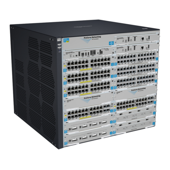
■ ■ Switch operation overview The Series 8212zl Switch is typically ordered as the base system (J8715A) with one management module, one system support module, two fabric modules, and the fan tray pre-installed. A spare chassis-only (J9091A) can be ordered, but it only comes with a fan tray pre-installed. - Page 12 Introducing the ProCurve Series 8200zl Switch Figure 1-1. ProCurve Switch 8212zl (J8715A) Base System See “Switch Features” on be installed in the ProCurve Series 8200zl Switch (modules available when this manual was printed). page 1-15 for a list of the switch modules that can...
-
Page 13: Front Of The Switch
Self Test LED Fans, Power Supplies, and Switch Modules with Link and Mode LEDs for each port located on each module Figure 1-2. Front of 8212zl Switch, Base System Introducing the ProCurve Series 8200zl Switch Management Module Reset button, and Status... -
Page 14: Leds
The Status LED for the module or other device with the fault will flash simultaneously. On briefly at the beginning of switch self test after the switch is powered on or reset. If on for a prolonged time, the switch has encountered a fatal hardware failure, or has failed its self test. - Page 15 Indicates the switch is processing a USB command file. orange) For more green information see the Management and On green The switch has finished processing the USB command file successfully. Configuration Guide Blinking Indicates an error condition. for your switch. orange...
- Page 16 The switch self test and initialization are in progress after you have power cycled or reset the switch. The switch is not operational until this LED goes off. The Self Test LED also comes on briefly when you “hot swap” a module into the switch and the module is automatically self tested.
- Page 17 An over temperature condition has been detected. On green The cooling fans are operating normally. (green/orange) Blinking One or more of the cooling fans have failed. The switch Fault LED will be blinking orange simultaneously. Internal Power 1-4 On green...
- Page 18 • if the Port LED is on continuously, the port is operating at 1000 Mbps Reserved for future development Modules A-L (green A module is installed in the switch module slot corresponding to the letter and - letters the module is undergoing or has passed self test. This also occurs when you corresponding to install a module when the switch is already powered on (“hot swap”).
- Page 19 • the port is not receiving link beat or sufficient light • the port has been disabled through the switch console, the web browser Blinking The port has failed self test. The switch Fault, Self Test LEDs, and appropriate module status LEDs will flash simultaneously. Mode...
-
Page 20: Led Mode Select Button And Indicator Leds
To optimize the amount of information that can be displayed for each of the switch ports, the Series 8212zl Switch uses a Mode LED for each port. The operation of this LED is controlled by the LED Mode Select button on the switch chassis, and the current selection is indicated by the mode indicator LEDs near the button. -
Page 21: Console Port
Off = PoE is not being supplied on this port. Console Port This port is used to connect a console to the switch by using the serial cable supplied with the switch. This connection is described under “Connecting a Console to the Switch” in chapter 2, “Installing the Series 8212zl Switch”. The console is a full-featured interface that can be used to configure, monitor, and troubleshoot the switch. -
Page 22: Clear Button
This button is provided for your convenience, but its presence means that if you are concerned with the security of the switch configuration and operation, you should make sure the switch is installed in a secure location, such as a locked wiring closet. -
Page 23: Back Of The Switch
Figure 1-8. Back of a 8212zl Switch with two Power Supplies Power Connector The Series 8200zl Switch does not have a power switch; it is powered on when connected to an active AC power source. The Series 8200zl Switch automati-... -
Page 24: Redundant Power Supply
Redundant Power Supply Load-sharing redundant power supplies (ProCurve Switch zl 875 W Power Supply, J8712A or a ProCurve Switch zl 1500 W Power Supply J8713A) can be installed in the back of the Series 8200zl Switch. To provide redundancy, each power supply should be connected to different AC power sources. -
Page 25: Switch Features
Switch Features The features of the Series 8200zl Switch include: If there are two Management modules installed in the switch, they are hot ■ swappable one at a time. ■ The two Fabric modules are hot swappable one at a time. - Page 26 Module high performance—The 8212zl Switch has a routing/switching capacity of ■ 576 Gbps, with a switch fabric speed of 692 Gbps and a throughput of 428 Mpps. ■ plug-and-play networking—all ports are enabled—just connect the network cables to active network devices and your switched network is operational.
-
Page 27: Installing The Series 8200Zl Switch
Installing the Series 8200zl Switch The Series 8200zl Switch is easily installed. It comes with an accessory kit that includes the brackets for mounting the switch in a standard 19-inch telco rack, or in an equipment cabinet. The switch has rubber feet already attached so they can be securely located on a horizontal surface. -
Page 28: Power Cords
Installing the Series 8200zl Switch Power Cords Power Cords Power cords and power supplies must be ordered separately, they are not included with the chassis when shipped. Order one of the following power cords depending on your region and model of power supply. -
Page 29: Installation Procedures
8212zl. Summary Follow these easy steps to install your switch. The rest of this chapter provides details on these steps. Prepare the installation site environment into which you will be installing the switch is properly prepared including having the correct network cabling ready to connect to the switch, and having a good location for the switch. - Page 30 Configuration changes can be made easily through the switch’s console interface. At this point, the switch is fully installed. See the rest of this chapter if you need more detailed information on any of these installation steps.
-
Page 31: Installation Precautions
The rack or cabinet should be adequately secured to prevent it from becoming unstable and/or falling over. ■ Ensure a cover plate is installed on any empty switch power supply or module slot. A cover plate is required for safe operation, and to ensure proper switch cooling. Never have more than one power supply or module slot uncovered at a time while the switch is powered on. - Page 32 C a u t i o n s ■ If the switch is to be shipped in a rack, use only an HP 10000 series rack and a rail mounting kit (5070-0145) for each switch and ensure the power supplies have been removed before shipping.
-
Page 33: Prepare The Installation Site
This is equivalent to 20km of the fiber-optic cable. For distances less than 20km, you must add attenuators to bring the total attenuation to at least 5db. Most cable vendors carry attenuators. page B-1 Summary of Cable Types to Use with the Switch Length Limits Twisted-Pair Cables... - Page 34 Installing the Series 8200zl Switch Installation Procedures Port Type Cable Type 10-GbE SR Multimode fiber-optic cable designed for Gigabit Ethernet: 62.5/125 μm (core/cladding) diameter or 50/125 μm, 850 nm, low metal content, complying with the ITU-T G.652 and ISO/IEC 793-2 Type B1 standards.
-
Page 35: Installation Location
Before installing the switch, plan its location and orientation relative to other devices and equipment: ■ In the front of the switch, allow at least 7.6 cm (3 inches) of space for the twisted-pair and fiber-optic cabling. ■ In the back of the switch, allow at least 10.2 cm (4 inches) of space for the power cord and cooling. - Page 36 2-6 Use a #1 Phillips (cross-head) screwdriver and attach the mounting brackets to the switch with the included 8-mm M4 screws. For the Switch 8200zl, each bracket is attached with four screws as shown in the following illustration. 8 mm M4 screws Figure 2-2.
- Page 37 Figure 2-3. Mounting Screw Positioning Place the switch in the rack and lower it so the notches in the bottom of the bracket slide onto the screws, then tighten these screws. Installing the Series 8200zl Switch...
- Page 38 Installing the Series 8200zl Switch Installation Procedures lower the switch with mounting brackets onto the partially installed screws, then tighten these screws Figure 2-4. Notches in Bracket Being Installed 2-12...
-
Page 39: Horizontal Surface Mounting
Place the switch on a table or other horizontal surface. Use a sturdy surface in an uncluttered area. You may want to secure the networking cables and switch power cord to the table legs or other part of the surface structure to help prevent people from tripping over the cords. -
Page 40: Install Switch Modules
Torx T-10 screwdriver. Retain the slot cover for future use. M o d u l e Any of the supported Switch zl Modules can be installed in any of the slots. ■ I n s t a l l a t i o n ■... - Page 41 Installing the Series 8200zl Switch Installation Procedures Insert module into the guides and slide it in until it is fully inserted. Open extractor handles Figure 2-1. Module Being Installed in a Chassis 2-15...
- Page 42 Installing the Series 8200zl Switch Installation Procedures Use the extractor handles to seat the module completely. Figure 2-6. Chassis with Module Fully Installed 2-16 Then tighten the retaining screws on the module until they are secure, but do not overtighten them.
-
Page 43: Install A Power Supply
Another, load-sharing redundant power supply (either a ProCurve Switch zl 875 W Power Supply (J8712A), or a ProCurve Switch zl 1500 W Power Supply (J8713A) can be installed in the back of the switch. The 8212zl can hold up to four power supplies. - Page 44 The switch power supplies are hot swappable; they can be installed while the switch is receiving power from the supply in the other slot. But, as indicated by the caution statement on the power supply, the supply must not be connected to AC power before being installed or removed.
- Page 45 Once the power supply is installed, tighten the four retaining screws that hold it in place. The screws can be tightened with either a flat-bladed or Torx T-10 screwdriver. Be careful not to overtighten the screws. tighten the four screws Figure 2-8. Back of Switch with Power Supply Fully Installed 2-19...
-
Page 46: Verify The Switch Passes Self Test
Figure 2-9. Power Connector on Back of Switch N o t e The Series 8200zl Switch does not have a power switch. It is powered on when the power cord is connected to the switch and to a power source. -
Page 47: Led Behavior
Switch Fault LED Figure 2-10. Switch Fault, Module, and Chassis LEDs When the switch is powered on, it performs its diagnostic self test. The entire download, initialization, and self test process can take up to 2 minutes for a fully loaded chassis, depending on the number and type of modules installed in the switch. -
Page 48: Install The Grounding Wire
If the ports are not connected to active network devices, the LEDs will stay off. 6. Install the Grounding Wire If a grounding wire is to be attached to the switch chassis, the grounding lug must be removed and a wire crimped to it and the grounding lug must be reinstalled. -
Page 49: Optional) Connect A Power Supply Shelf
LEDs. EPS Operation The EPS has a mechanism for detecting that it is connected to a valid switch with an EPS cable. When the EPS is connected to a powered switch it will provide additional PoE power to the switch within 2 seconds. -
Page 50: Operating Characteristics Of The Eps (J8714A)
8200zl Series switches because if the PoE power is not planned and implemented correctly the end devices connected to the switch ports may not receive power if an internal switch PoE power supply should fail. For further information regarding the Power Supply Shelf PoE... -
Page 51: Connecting The Power Supply Shelf
Power Status LEDs Device Connected LEDs Connecting the Power Supply Shelf To Power Source Figure 2-12. Connecting the EPS to one 8200zl switch To Power Source 8200zl To Power Source EPS Cables Installing the Series 8200zl Switch Installation Procedures 2-25... -
Page 52: Connect The Network Devices
In general for all the modules, when a network cable from an active network device is connected to the switch, the Link LED for the switch port should go on. If the Link LED does not go on, use the table below to help solve the problem, and see the module documentation for troubleshooting procedures. - Page 53 Diagnostic Tip Try the following procedures: Port LED is still off when • For the indicated port, verify both ends of the cabling, at the switch and the connected device, are a cable is securely connected. connected • Verify the connected device and switch are both powered on and operating correctly.
-
Page 54: 10. (Optional) Connect A Console To The Switch
Series 8200zl Switch. If the PC or terminal has a 25-pin serial connector, you can use a readily available 9-pin to 25-pin serial cable, or attach a 9-to-25 pin straight-through adapter to the PC end of the cable. -
Page 55: Direct Console Access
If you want to operate the console using a different configuration, ensure you change the settings on both the terminal and on the switch. Change the switch settings first, then change the terminal settings, and reestablish the console session. Direct Console Access... -
Page 56: Console Cable Pinouts
RJ-45 (Signal reference from Chassis TX_Debug RX_Debug Telnet Console Access To access the switch through a telnet session, using an Ethernet port not the Console port, follow these steps: 2-30 DB-9 (Signal reference from PC) 1 2 3 4 5 6 7 8... -
Page 57: Hot Swapping Switch Modules
If a module has to be replaced with one of the same type, or you are expanding the switch capability by adding a module in a slot where one was not previ- ously installed (since the last switch reboot), the replaced or new module is immediately operational;... - Page 58 ■ boot Switch option from the switch console menu, the web browser interface, or ProCurve Manager. Until the switch is rebooted, the module will not operate and the Module Status LED for the affected slot will continue to flash. 2-32...
-
Page 59: Example Network Topologies
Series 8200zl Switch Phones, APs and other peripherals Figure 2-17. Basic Switch Connectivity The Series 8200zl Switch can provide basic network connectivity to a high number of PoE devices. These devices can be easily connected, as shown in the above illustration. 2-33... -
Page 60: Use As An Edge Switch
When your network expands and the users need to access resources beyond the edge of the local network, the Series 8200zl Switch is an excellent platform for that expansion. With the flexibility of 12 slots, the high port count 10/100/... -
Page 61: Optimizing The 10-Gbe Port Configuration
Optimizing the 10-GbE Port Configuration The 10-GbE ports on the ProCurve Series 8200zl switch are designed to deliver full 10 Gbps wire-speed to each port, where either one or two ports are in a linked state with another device. When three or four 10-GbE ports are in a linked state, when using an X2 (J8708A) or CX4 (J8707A) module, the 10-GbE ports support an aggregate bandwidth of 28.8 Gbps across the linked ports. - Page 62 Installing the Series 8200zl Switch Example Network Topologies Port A1 is guaranteed 10 Gbps because it does not need to share the channel with port A4 Figure 2-20. Guaranteeing 10 Gbps on a specific port. 2-36 Ports A2 and A3 share this channel...
-
Page 63: Getting Started With Switch Configuration
Getting Started With Switch Configuration This chapter is a guide for using the console Switch Setup screen to quickly assign an IP (Internet Protocol) address and subnet mask to the switch, set a Manager password, and, optionally, configure other basic features. -
Page 64: Using The Switch Setup Screen
The quickest and easiest way to minimally configure the switch for manage- ment and password protection in your network is to use a direct console connection to the switch, start a console session, and access the Switch Setup screen. Using the method described in the preceding section, connect a terminal device to the switch and display the switch console command (CLI) prompt (the default display). - Page 65 Recommended; If you set IP Config to Manual, then enter an IP address Note: The IP address and subnet mask assigned for the switch must be compatible with the IP addressing used in your network. For more information on IP addressing, see the Management and Configuration Guide which is on the ProCurve Web site.
-
Page 66: Where To Go From Here
The above procedure configures your switch with a Manager password, IP address, and subnet mask. As a result, with the proper network connections, you can now manage the switch from a PC equipped with Telnet, a web browser interface, or from an SNMP-based network management station using a tool such as ProCurve Manager. -
Page 67: Using The Ip Address For Remote Switch Management
With your Series 8200zl Switch, you can use the switch’s IP address to manage the switch from any PC that is on the same subnet as the switch. You can use either a Telnet session or a standard web browser to manage the switch. - Page 68 5-1 An extensive help system is also available for the web browser interface. To access the help system though, the subnet on which the switch is installed must have access to the internet, or ProCurve Manager needs to be installed on a network management station that is on the subnet.
-
Page 69: Configuring The Procurve Wireless Edge Services Zl Module (J9051A)
LAN services ■ Configuring an IP Address for the Module By default, the module uses DHCP to get an IP address. The zl switch CLI has a command context, the wireless-services context, for configuring and man- aging a module. - Page 70 To display the module’s IP address, enter: ProCurve (wireless-services-id)# show ip interfaces The following example enters the wireless-services context of a module installed in Slot B of a zl switch and then displays the IP address assigned by DHCP to the module: ProCurve# wireless-services b...
-
Page 71: Configuring Vlans On The Zl Switch
Configuring VLANs on the zl Switch In a wireless services-enabled zl switch, the Wireless Edge Services zl Module and the Redundant Wireless Services zl Module use ports on the switch to pass wired and wireless traffic to and from the network. An uplink VLAN, containing the module’s uplink port, communicates with the wired side of the... -
Page 72: Configuring Wireless Lan Services
The CLI commands available in the wireless-services context of the zl switch CLI are documented in an appendix of the ProCurve Wireless Edge Services zl Modules Management and Configuration Guide. Refer to this manual for more information. -
Page 73: Replacing Components
Use an antistatic wrist strap and observe all static precautions when hot swapping components. For example, connect your antistatic wrist strap to the ground point on the front of the switch, above the rightmost power supply bay. W A R N I N G This unit may have more than one power supply cable. -
Page 74: Replacing Power Supplies
PoE power to lower priority ports. If more than one power supply fails while the switch is at or near maximum operating power (that is: the sum total of all PoE supply capacity minus the largest supply, see chapter 2 and 4 of the ProCurve Power over Ethernet (PoE) for zl and yl Products), loss of all PoE power may result. - Page 75 Using either a flat-bladed or Torx T-10 screwdriver loosen the retaining screws and remove the failed power supply. Figure 4-1. Power Supply Removal Replacing Components Replacing Power Supplies...
- Page 76 Replacing Power Supplies Insert the power supply into the opening. Slide it all the way in until it connects to the switch. The power supply face plate will be flush with the back face of the switch. Figure 4-2. Power Supply Installation Tighten the four retaining screws that hold it in place.
-
Page 77: Replacing Fan Trays
Replacing Fan Trays When a fan fails the Fan Status LED on the switch chassis will blink simultaneously with the switch Fault LED. In this case, the entire fan tray needs to be replaced. You cannot replace individual fans. The fan tray is hot swappable. It can be removed and replaced without removing power from the switch. -
Page 78: Replacing The Management Module
Module, completing any synchronization of files and state information to the second (Standby) Management Module. N o t e If both Management Modules are removed from the switch at the same time, the switch will shutdown. If there is only one Management Module in the switch, ProCurve Networking recommends replacing the Management module, flash disk and battery (on the Management module) during scheduled down time. - Page 79 Replacing Components Replacing the Management Module Tighten the retaining screws. Retaining Screws Extractor Handles Figure 4-4. Management Module Removal and Installation...
-
Page 80: Replacing The Management Module Compact Flash Card
When a Flash card fails the Flash status LED on the management module will blink simultaneously with the switch Fault LED. Installing a Compact Flash Card To install (or replace) a Compact Flash card: Using either a flat-bladed or Torx T-10 screwdriver loosen the retaining screws securing the management module. -
Page 81: Replacing The Management Module Battery
The battery on the management module is used to keep time for the internal switch clock. There is no indicator LED for when the battery dies. The only indication will be the internal clock will not keep the correct time. - Page 82 Remove the old battery and dispose of properly. Insert the new battery with the lettering and the plus “+” sign facing up. Reinstall the management module into the switch. Use an equal amount of pressure and push both extractor handles closed to completely seat the module.
-
Page 83: Replacing The J9154X Module Compact Flash Card
Services Module that contains both the boot software and configuration files. When a Flash card fails the “CF Status” LED on the Services Module will blink simultaneously with the switch Fault LED. Installing a Compact Flash Card To install (or replace) a Compact Flash card: Using either a flat-bladed or Torx T-10 screwdriver loosen the retaining screws securing the module. -
Page 84: Replacing The J9154X Module Disk Drive
The hard disk drive (HDD) is the primary storage medium located on the Services Module. When a disk drive fails the “HDD status” LED on the Services Module will blink simultaneously with the switch Fault LED. Installing a Disk Drive... -
Page 85: Troubleshooting
Troubleshooting This chapter describes how to troubleshoot your Series 8200zl Switch. Note that this document describes troubleshooting mostly from a hardware perspective. You can perform more in-depth troubleshooting using the soft- ware tools available with the switch, including the full-featured console interface, the built-in web browser interface, and ProCurve Manager, the SNMP-based network management tool. - Page 86 Troubleshooting Basic Troubleshooting Tips cable to the cable in appendix B, “Switch Ports and Network Cables” for pinouts and correct cable wiring. A category 5 cable tester is a recom- mended tool for every 100Base-TX and 1000Base-T network installation. Improper Network Topologies. It is important to make sure you have ■...
- Page 87 Because the Series 8200zl Switch behaves in this way (in compliance with the IEEE 802.3 standard), if a device connected to the switch has a fixed configuration at full duplex, the device will not connect correctly to the switch. The result will be high error rates and very inefficient communi- cations between the switch and the device.
-
Page 88: Diagnosing With The Leds
Troubleshooting Diagnosing with the LEDs Diagnosing with the LEDs Table 5-1 shows LED patterns on the switch and the switch modules that indicate problem conditions. Check in the table for the LED pattern you see on your switch Refer to the corresponding diagnostic tip on the next few pages. -
Page 89: Diagnostic Tips
Number Problem ➊ The power supplies 1. Verify the power cord is plugged into an active power source and to the switch. installed in the Ensure these connections are snug. switch are not 2. Try power cycling the switch by unplugging and plugging the power cord back in. - Page 90 The modules are all tested whenever the switch is powered on, or reset (through installed in the slot the Reset button on the switch, or the Boot or Reset options in the console or web that corresponds to browser interface), and when they are hot swapped (installed when the switch is the letter that is powered on).
- Page 91 LEDs again. If the error indication reoccurs, may have failed. one or more of the fans has failed. The switch has multiple fans and may continue to operate OK under this condition if the ambient temperature does not exceed normal room temperature, but for best operation, the fan tray should be replaced.
- Page 92 The network Try the following procedures: connection is not • For the indicated port, verify both ends of the cabling, at the switch and the working properly. connected device, are securely connected. • Verify the connected device and switch are both powered on and operating correctly.
-
Page 93: Proactive Networking
■ performance of your network The following interfaces provide tests, indicators, and an event log that can be used to monitor the switch and its network connections, and to help you take advantage of these proactive networking features: ■ ProCurve Manager - an SNMP-based network management tool included... -
Page 94: Hardware Diagnostic Tests
Hardware Diagnostic Tests Reasons for Resetting the Switch Generally, you only need to reset the switch when it needs to recognize a change in its hardware or software (console) configuration. Some circumstances in which you will need to reset the switch are: ■... -
Page 95: Testing The Switch By Resetting It
Checking the Switch LEDs The self-test passes if the Fault and Test LEDs on the front of the switch go off after approximately 90 to 150 seconds depending on the number and type of modules installed in the switch. If these LEDs stay on longer than 180 seconds or begin blinking, the switch, or a module, or an individual mini-GBIC may have to be replaced as indicated by the LEDs. -
Page 96: Testing Twisted-Pair Cabling
For example, if you have two PCs on the network that have LAN adapters between which you can run a link-level test or Ping test through the switch, you can use this test to verify the entire communication path between the two PCs is functioning correctly. See your LAN adapter documentation for more information on running the a link test or Ping test. -
Page 97: Restoring The Factory Default Configuration
Returning the configuration of these features to their factory default settings (usually disabling them) may result in network connectivity issues. If the switch has a valid configuration, and you are restoring the factory default settings for a reason other than configuration problems, you should save the switch configuration prior to performing the factory default reset. -
Page 98: Downloading New Code
24 hours a day, seven days a week through the use of a number of automated electronic services. See the Customer Support/Warranty booklet that came with your switch for information on how to use these services to get technical support. The ProCurve Networking Web site, provides up-to-date support information. -
Page 99: Physical
• Switch 8212zl (J8715A) Base System Electrical The Series 8200zl Switch automatically adjusts to any voltage between 100-127 and 200-240 volts when using the J8712A power supply, and 200-240 volts only when using the J8713A power supply, and either 50 or 60 Hz. -
Page 100: Environmental
Specifications Environmental Temperature: Relative humidity: (non-condensing) Maximum altitude: Temperature: SR Optic J8436A LR Optic J8437A ER Optic J8438A LRM Optic J9144A Copper J8440B Relative humidity: (non-condensing) Maximum altitude: Acoustic Geräuschemission LpA = 59.2 dB am fiktiven Arbeitsplatz nach DIN 45635 T.19 Noise Emission LpA = 59.2 dB in a virtual workspace according to DIN 45635 T.19 Network Connectors... -
Page 101: Safety
■ The fiber-optic ports are compatible with the IEEE 802.1ae standards. Safety EN60950 ■ ■ CSA 22.2 No. 60950 UL 60950 ■ ■ IEC 60950 EMC compliance (Class A) Complies with: VCCI ■ ■ EN55022/CISPR-22 Lasers The following products are Class 1 Laser Products. Laser Klasse 1: ■... -
Page 103: B Switch Ports And Network Cables
Switch Ports and Network Cables This appendix includes switch connector information and network cable information for cables that should be used with the Series 8200zl Switch, including minimum pin-out information and specifications for twisted-pair cables. N o t e Incorrectly wired cabling is the most common cause of problems for LAN communications. -
Page 104: Twisted Pair
ELFEXT, and Return Loss. When testing your cabling, be sure to include the patch cables that connect the switch and other end devices to the patch panels on your site. The patch cables are frequently overlooked when testing cable and they must also comply with the cabling standards. -
Page 105: Fiber-Optic Cables
9/125 μm (core/cladding) diameter, 1310 nm, 10-GbE LR low metal content, single mode fiber-optic cables, complying with the ITU-T G.652 and ISO/IEC 793-2 Type B1 standards. Switch Ports and Network Cables Connector Type Maximum Length • 62.5 μm cable: LC - Gigabit-SX mini-GBIC –... -
Page 106: Copper Cables
Switch Ports and Network Cables Port Type Cable Specifications 9/125 μm (core/cladding) diameter, 1550 nm, 10-GbE ER low metal content, single mode fiber-optic cables, complying with the ITU-T G.652 and ISO/IEC 793-2 Type B1 standards. 10-GbE Multimode fiber-optic cable designed for Gigabit Ethernet: 62.5/125 μm or 50/125 μm... -
Page 107: Mode Conditioning Patch Cord For Gigabit-Lx
If you experience a high number of transmission errors on the Gigabit-LX ports, usually CRC or FCS errors, you may need to install one of these patch cords between the Gigabit-LX port in your switch and your multimode fiber- optic network cabling, and between the Gigabit-LX transmission device and the network cabling at the other end of the multimode fiber-optic cable run. -
Page 108: Installing The Patch Cord
Twisted-Pair Cable/Connector Pin-Outs The HP Auto-MDIX Feature In the default configuration, “Auto”, the 10/100Base-TX ports on the 10/100-TX and PoE zl Modules used in the Series 8200zl Switch all automatically detect the type of port on the connected device and operate as either an MDI or MDI-X port, whichever is appropriate. - Page 109 N o t e HP Auto-MDIX was developed and shared with the IEEE for the development of the IEEE 802.3ab standard. HP Auto-MDIX and the IEEE 802.3ab Auto MDI/ MDI-X feature are completely compatible. If you connect a Series 8200zl Switch twisted-pair port to another switch or hub, which typically have MDI-X ports, the Series 8200zl Switch port automat- ically operates as an MDI port.
-
Page 110: Straight-Through Twisted-Pair Cable For 10 Mbps Or 100 Mbps Network Connections
Straight-Through Twisted-Pair Cable for 10 Mbps or 100 Mbps Network Connections Because of the HP Auto-MDIX operation of the 10/100 ports on the switches, for all network connections, to PCs, servers or other end nodes, or to hubs or other switches, you can use straight-through cables. -
Page 111: Crossover Twisted-Pair Cable For 10 Mbps Or 100 Mbps Network Connection
Crossover Twisted-Pair Cable for 10 Mbps or 100 Mbps Network Connection The HP Auto-MDIX operation of the 10/100 ports on the switches also allows you to use crossover cables for all network connections, to PCs, servers or other end nodes, or to hubs or other switches. -
Page 112: Straight-Through Twisted-Pair Cable For 1000 Mbps Network Connections
Switch Ports and Network Cables Twisted-Pair Cable/Connector Pin-Outs Straight-Through Twisted-Pair Cable for 1000 Mbps Network Connections 1000Base-T connections require that all four pairs or wires be connected. Cable Diagram Figure B-4. Straight-through Cable Diagram for 1000 Mbps Network Connection N o t e Pins 1 and 2 on connector “A”... -
Page 113: C Safety And Regulatory Statements
These products do not have a power switch; they are powered on when the power cord is plugged in. Documentation reference symbol. If the product is marked with this symbol, refer to the product documentation to get more information about the product. -
Page 114: Informations Concernant La Sécurité
Safety and Regulatory Statements Informations concernant la sécurité Informations concernant la sécurité WARNING Caution Cet appareil est un produit de classe I et possède une borne de mise à la terre. La source d'alimentation principale doit être munie d'une prise de terre de sécurité installée aux bornes du câblage d'entrée, sur le cordon d'alimentation ou le cordon de raccordement fourni avec le produit. -
Page 115: Hinweise Zur Sicherheit
Hinweise zur Sicherheit Symbol für Dokumentationsverweis. Wenn das Produkt mit diesem Symbol markiert ist, schlagen Sie bitte in der Produktdokumentation nach, um mehr Informationen über das Produkt zu erhalten. WARNING Symbol für Dokumentationsverweis. Wenn das Produkt mit diesem Symbol markiert ist, schlagen Sie bitte in der Produktdokumentation nach, um mehr Informationen über das Produkt zu erhalten. -
Page 116: Considerazioni Sulla Sicurezza
Safety and Regulatory Statements Considerazioni sulla sicurezza Considerazioni sulla sicurezza WARNING Caution Questo prodotto è omologato nella classe di sicurezza I ed ha un terminale protettivo di collegamento a terra. Dev'essere installato un collegamento a terra di sicurezza, non interrompibile che vada dalla fonte d'alimentazione principale ai terminali d'entrata, al cavo d'alimentazione oppure al set cavo d'alimentazione fornito con il prodotto. -
Page 117: Consideraciones Sobre Seguridad
Consideraciones sobre seguridad Símbolo de referencia a la documentación. Si el producto va marcado con este símbolo, consultar la documentación del producto a fin de obtener mayor información sobre el producto. WARNING Una WARNING en la documentación señala un riesgo que podría resultar en lesiones o la muerte. -
Page 118: Safety Information (Japan
Safety and Regulatory Statements Safety Information (Japan) Safety Information (Japan) -
Page 119: Safety Information (China
Safety and Regulatory Statements Safety Information (China) Safety Information (China) -
Page 120: Emc Regulatory Statements
Safety and Regulatory Statements EMC Regulatory Statements EMC Regulatory Statements U.S.A. FCC Class A This equipment has been tested and found to comply with the limits for a Class A digital device, pursuant to Part 15 of the FCC Rules. These limits are designed to provide reasonable protection against interference when the equipment is operated in a commercial environment. -
Page 121: Korea
Korea Taiwan Regulatory Model Identification Number For regulatory identification purposes, the ProCurve Series 8200zl Switch is assigned a Regulatory Model Number. The Regulatory Model Number for these switches is RSVLC- 0503. This regulatory number should not be confused with the marketing name (ProCurve Series 8200zl Switch), or product numbers (J9091A, J8715A). -
Page 122: European Community
Safety and Regulatory Statements EMC Regulatory Statements European Community C-10... -
Page 123: Regulatory Information (China
Safety and Regulatory Statements EMC Regulatory Statements Regulatory Information (China) C-11... -
Page 125: D Recycle Statements
Recycle Statements Waste Electrical and Electronic Equipment (WEEE) Statements Disposal of Waste Equipment by Users in Private Household in the European Union This symbol on the product or on its packaging indicates that this product must not be disposed of with your other household waste. - Page 126 Recycle Statements Waste Electrical and Electronic Equipment (WEEE) Statements Laitteiden hävittäminen kotitalouksissa Euroopan unionin alueella Jos tuotteessa tai sen pakkauksessa on tämä merkki, tuotetta ei saa hävittää kotitalousjätteiden mukana. Tällöin hävitettävä laite on toimitettava sähkölaitteiden ja elektronisten laitteiden kierrätyspisteeseen. Hävitettävien laitteiden erillinen käsittely ja kierrätys auttavat säästämään luonnonvaroja ja varmista- maan, että...
- Page 127 Smaltimento delle apparecchiature da parte di privati nel territorio dell'Unione Europea Questo simbolo presente sul prodotto o sulla sua confezione indica che il prodotto non può essere smaltito insieme ai rifiuti domestici. È responsabilità dell'utente smaltire le apparecchiature consegnan- dole presso un punto di raccolta designato al riciclo e allo smaltimento di apparecchiature elettriche ed elettroniche.
- Page 128 Para obter mais informações sobre locais que reciclam esse tipo de material, entre em contato com o escritório da HP em sua cidade, com o serviço de coleta de lixo ou com a loja em que o produto foi adquirido.
- Page 129 10-GbE port configuration, optimizing … 2-35 Act LED … 1-8 Actv LED … 1-6 auto MDI/MDI-X operation … B-8, B-10 HP Auto-MDIX feature … B-6 auxiliary or USB port location on switch … 1-3 back of switch description … 1-13 power connector …...
- Page 130 3, 4, 5 … B-7 connector pin-outs … B-6 crossover cable pin-out … B-9 HP Auto-MDIX feature … B-6 MDI-X to MDI connections … B-8, B-10 MDI-X to MDI-X connections … B-9 note on requirements for 1000Base-T … B-2 pin-outs …...
- Page 131 … 1-16 modules … 1-15 hot swapping … 4-1 redundant power supply … 1-14, 2-18 resetting the switch for new module type … 2-31 switch modules … 2-31 HP Auto-MDIX feature description … B-6 in-band console access, types of … 2-28 managing the switch …...
- Page 132 … 2-7 1000Base-LH connections … 2-7 1000Base-LX connections … 2-7 1000Base-SX connections … 2-7 fiber-optic, specifications … B-3 HP Auto-MDIX feature … B-6 required types … 2-7 twisted-pair connector pin-outs … B-6 twisted-pair, specifications … B-2 twisted-pair, wiring rules … B-7 network devices connecting to the switch …...
- Page 133 … 5-3 port LEDs Link … 1-9 Mode … 1-9 ports console … 2-28 HP Auto-MDIX feature … B-6 network connections … 2-26 power connector … 1-13 Power LED behavior during error conditions … 5-4 behavior during self test … 2-21 description …...
- Page 134 … B-8, B-10 use with fixed port configurations … B-7 subnet mask, configuring … 3-3 summary of cables used with the switch … 2-7 of switch installation … 2-3 supported mini-GBICs … 1-15 supported X2 fiber optic transceivers … 1-15 switch connecting to a power source …...
- Page 135 … B-8, B-10 switch-to-computer connection … B-8, B-10 switch-to-switch or hub connection … B-9 testing … 5-12 twisted-pair ports HP Auto-MDIX feature … B-6 VT-100 terminal serial cable connection for … 2-29 wiring rules for twisted-pair cables … B-7 X2 transceivers supported types …...
- Page 138 © Copyright 2008 - 2009 Hewlett-Packard Development Company, L.P. Printed in Singapore January 2009 Manual Part Number 5992-3072 *5992-3072*...