
Related Manuals for Omega 871A


Summary of Contents for Omega 871A
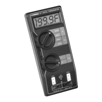
- Page 1 User’ s Guide ® http://www.omega.com e-mail: info@omega.com Only model 871A has CE certification 871A and 872A Digital Thermometers...
- Page 2 CE mark to every appropriate device upon certification. The information contained in this document is believed to be correct but OMEGA Engineering, Inc. accepts no liability for any errors it contains, and reserves the right to alter specifications without notice.
-
Page 3: Table Of Contents
Equipment Needed ..............8 4.3.2 Environmental Conditions............8 4.3.3 Setup..................8 4.3.4 Calibration Procedure ..............9 Disassembly for Model 871A and Model 872A......10 Troubleshooting Guide .............11 4.5.1 DC Voltage checks Model 871A ..........12 4.5.2 DC Voltage Checks Model 872A ..........12 4.5.3 Waveform Checks Model 871A ..........13... -
Page 4: Section 1 Introduction
1ºC over the entire measurement span of the instrument. Although the 871A and 872A are ideal for temperature measurement in the field, they also function well as bench instruments when equipped with the optional tilt stand. The Model 871A and Model 872A provide dual inputs, selectable scales (ºF/ºC), 1.0º... -
Page 5: Section 2 Installation
SECTION INSTALLATION UNPACKING Remove the Packing List and verify that all equipment has been received. If there are any questions about the shipment, please call OMEGA Customer Service Department at 800-622-2378 or (203) 359-1660. The following items are included: Quantity... -
Page 6: Section 3 Operation
Figure 2-1. Battery Installation SECTION OPERATION The Model 871A is designed to work with any type K thermocouple probe or sen- sor, fitted with an OMEGA miniature thermocouple connector SMP-K-M or industry equivalent. The Model 872A is designed to work with any type J thermocouple probe or sensor, fitted with an OMEGA miniature connector SMP-J-M or industry equivalent. - Page 7 TABLE 3-1 MODEL 871A AND MODEL 872A CONTROLS AND INDICATORS ITEM CONTROL/INDICATOR FUNCTION ON/OFF switch Turns unit on or off. Scale and range selector Allows user to select: ºF or ºC scale, any of four possible thermocouple ranges, and 1.0º or 0.1º resolution.
-
Page 8: Operating Procedure
Functionality Check Attach the GG-TC-K-24-36-SMP beaded wire thermocouple probe (supplied) to the Model 871A and the GG-TC-J-24-36-SMP beaded wire thermocouple probe (supplied) to the Model 872A. Hold the sensor end between two fingers. The reading should change from ambient to between... -
Page 9: Accuracy Check
2. 100: 1 divider: 1.98 kilohm and 20 ohm wirewound resistors with 0.02% ratio accuracy or better. 3. OMEGA TRC III Ice Point Reference Chamber or distilled water ice bath. 4. OMEGA type K TRP Reference Probe or make a thermocouple transi- tion junction (see paragraph 4.2.3). -
Page 10: Setup
2. Connect the thermocouple wires from the type K transition junction to an OMEGA miniature thermocouple connector SMP-K-M. 3. Plug in the miniature connector to input TC1 of the Model 871A. 4. Connect the copper wires to the 100:1 divider (see Figure 4-1) with the copper/wire (positive) junction connected through the 1.98 kilohm... -
Page 11: Calibration For Model 872A
2. 100: 1 divider: 1.98 kilohm and 20 ohm wirewound resistors with 0.02% ratio accuracy or better. 3. OMEGA TRC III Ice Point Reference Chamber or distilled water ice bath. 4. OMEGA type J TRP Reference Probe or make a thermocouple transition junction (see paragraph 4.3.3). -
Page 12: Calibration Procedure
3. Plug in the miniature connector to input TC1 of the Model 872A. 4. Connect the copper wires to the 100:1 divider (see Figure 4-3) with the iron wire connected through the 1.98 kilohm resistor, to the dc calibra- tor positive terminal. 5. -
Page 13: Disassembly For Model 871A And Model 872A
DISASSEMBLY FOR MODEL 871A AND MODEL 872A The PC board and LCD assembly are not secured once the case retaining screws are removed. Be careful not to allow the PC board and LCD assembly to fall out or shift out of position. -
Page 14: Troubleshooting Guide
To gain access to the PC board, refer to the first three paragraphs of the disassembly instructions. Utilize the Parts List, Schematic and Component Layout for identifying parts and checkpoint locations. The following checks should be made with the Models 871A and 872A set to the 200ºC Range. -
Page 15: Dc Voltage Checks Model 871A
4.5.1 DC Voltage Checks For Model 871A 1. Battery: VBAT > 7 V 2. Power Supplies: È V + to (Analog Ground) = +2.8 ± 0.4 V È (Digital Ground) = +5 ± 1 V V + to È 3. Reference Diode: CR101 to (Analog Ground) = -1.23 ±... -
Page 16: Waveform Checks Model 871A
4.5.3 Waveform Checks For Model 871A Waveform Checks: Referenced To È (Digital Ground) Clock U111, Pin 3 360 kHz, 5V pp Square Wave A/D Clock U112, Pin 5 40 kHz, 5V pp Rectangular Wave Ref. Clock 1 U102, Pin 9... - Page 17 10% of life remains DIMENSIONS: H: 7.0" (178 mm) x W: 3.1" (78 mm) x D: 1.6" (42 mm) WEIGHT: 10.6 oz. (300 grams) FOR MODEL 871A TEMPERATURE SENSOR: Type K (NiCr-NiAI) thermocouple RANGES: 200ºF, 2000ºF, 200ºC, 1370ºC TEMPERATURE SPAN: -40.0º...
- Page 18 SPECIFICATION (con’t) mV OUTPUT: Non-linearized, cold-junction compensated, amplified thermocouple output (Not isolated from selected TC input.) On ºC Scale: 1mV/ºC on 200º range 0.1mV/ºC on 1370º range 0ºC = OmV output On º F Scale: 5/9 mV/ºF on 200º range 5/90 mV/ºF on 2000º...
-
Page 19: Parts List
SPECIFICATION (con’t) mV OUTPUT: Non-linearized, cold-junction compen- sated, amplified thermocouple output (Not isolated from selected TC input.) On ºC Scale: 1mV/ºC on 200º range 0.1mVºC on 760º range 0ºC = OmV output On ºF Scale: 5/9 mV/ºF on 200º range 5/90 mV/ºF on 1400º... - Page 20 ** For Model 872A only S102 Switch, Rotary To order parts, specify model and circuit designation. S103 Switch, SPDT, ON-OFF TC-1, 2 TC Cable COMPONENT LAYOUT FOR MODEL 871A R120 R127 Jumper COMPONENT LAYOUT FOR MODEL 872A R118A R121 Jumper...
- Page 21 SCHEMATIC MODEL 871A DIGITAL THERMOMETER...
- Page 22 SCHEMATIC MODEL 872A DIGITAL THERMOMETER...
- Page 23 CONDITIONS: Equipment sold by OMEGA is not intended to be used, nor shall it be used: (1) as a “Basic Component” under 10 CFR 21 (NRC), used in or with any nuclear installation or activity; or (2) in medical applications or used on humans.
- Page 24 Where Do I Find Everything I Need for Process Measurement and Control? OMEGA…Of Course! TEMPERATURE Thermocouple, RTD & Thermistor Probes, Connectors, Panels & Assemblies Wire: Thermocouple, RTD & Thermistor Calibrators & Ice Point References Recorders, Controllers & Process Monitors Infrared Pyrometers PRESSURE, STRAIN AND FORCE Transducers &...