Table of Contents
Advertisement
Quick Links
Advertisement
Table of Contents

Related Manuals for Supermicro SBI-7426T-S3


Summary of Contents for Supermicro SBI-7426T-S3
- Page 1 SBI-7426T-S3 Blade Module User’s Manual Revison 1.0a...
- Page 2 This product, including software and documentation, is the property of Supermicro and/or its licensors, and is supplied only under a license. Any use or reproduction of this product is not allowed, except as expressly permitted by the terms of said license.
-
Page 3: About This Manual
Chapter 3: Setup and Installation Refer to this chapter for details on installing the SBI-7426T-S3 blade module into the Superblade chassis. Other sections cover the installation and placement of memory modules and the installation of hard disk drives into the blade module. - Page 4 SBI-7426T-S3 Blade Module User’s Manual Notes...
-
Page 5: Table Of Contents
........1-1 1-3 Blade Module Features ..............1-2 Processors ....................1-2 Memory ....................1-2 Storage....................1-3 Density ....................1-3 1-4 Contacting Supermicro ..............1-4 Chapter 2 System Safety ..............2-1 2-1 Electrical Safety Precautions ............2-1 2-2 General Safety Precautions ............. - Page 6 SBI-7426T-S3 Blade Module User’s Manual 3-9 Configuring and Setting up RAID ..........3-12 Chapter 4 Blade Module Features ..........4-1 4-1 Control Panel ..................4-2 Power Button ..................4-3 KVM Button..................... 4-3 LED Indicators ..................4-3 KVM Connector..................4-3 4-2 Mainboard ...................
- Page 7 Appendix A BIOS POST Codes ............A-1 A-1 BIOS POST Messages ..............A-1 A-2 BIOS POST Codes ................A-3 Recoverable POST Errors ..............A-4 Terminal POST Errors................A-4...
- Page 8 SBI-7426T-S3 Blade Module User’s Manual Notes viii...
- Page 9 Figure 4-3. B8DT6 Mainboard................4-4 Figure 4-4. Intel 5500 Tylersburg Chipset Block Diagram ........ 4-5 Figure 4-5. Exploded View of SBI-7426T-S3 Blade Module ......4-7 Figure 5-1. Advanced Settings Screen ............. 5-3 Figure 5-2. IDE Configuration Screen – Configure RAID Drives....... 5-4 Figure 5-3.
- Page 10 SBI-7426T-S3 Blade Module User’s Manual Notes...
- Page 11 Table 4-3. Blade Module LED Indicators ............4-3 Table 4-4. B8DT6 Mainboard Layout ..............4-5 Table 4-5. Main Components of SBI-7426T-S3 Blade Module ......4-7 Table 6-1. Main BIOS Setup Menu Options............6-5 Table 6-2. Advanced Setup Menu Options ............6-6 Table 6-3.
- Page 12 SBI-7426T-S3 Blade Module User’s Manual Notes...
-
Page 13: Chapter 1 Introduction
Chapter 1 Introduction Overview The SBI-7426T-S3 blade module is a compact self-contained server that connects into a pre-cabled enclosure that provides power, cooling, management and networking functions. One enclosure for the SBI-7426T-S3 blade module can hold fourteen blade units. In this manual, “blade system” refers to the entire system (including the enclosure and blades units), “blade”... -
Page 14: Blade Module Features
Please note that you will need to check the detailed specifications of a particular blade module for a list of the CPUs it supports. Details on installation of the processor into the SBI-7426T-S3 blade module are found in Chapter 3: "Setup and Installation" on page 3-1. -
Page 15: Storage
Chapter 1: Introduction Storage The SBI-7426T-S3 blade module can have three 2.5" SAS2 or SATA (Serial ATA) hard disk drives in front-mounted easy removable carriers. See Chapter 3: "Setup and Installation" on page 3-1 for storage installation details. Density A maximum of fourteen blade modules may be installed into a single blade enclosure. -
Page 16: Contacting Supermicro
SBI-7426T-S3 Blade Module User’s Manual Contacting Supermicro Headquarters Address: Super Micro Computer, Inc. 980 Rock Ave. San Jose, CA 95131 U.S.A. Tel: +1 (408) 503-8000 Fax: +1 (408) 503-8008 marketing@supermicro.com (General Information) Email: support@supermicro.com (Technical Support) Web Site: www.supermicro.com Europe Address: Super Micro Computer B.V. -
Page 17: Chapter 2 System Safety
Chapter 2 System Safety Electrical Safety Precautions Basic electrical safety precautions should be followed to protect yourself from harm and the SuperBlade from damage: • Be aware of how to power on/off the enclosure power supplies and the individual blades as well as the room's emergency power-off switch, disconnection switch or electrical outlet. -
Page 18: General Safety Precautions
SBI-7426T-S3 Blade Module User’s Manual General Safety Precautions Follow these rules to ensure general safety: • Keep the area around the SuperBlade clean and free of clutter. • Place the blade module cover and any system components that have been removed away from the system or on a table so that they won't accidentally be stepped on. -
Page 19: Chapter 3 Setup And Installation
This chapter covers the setup and installation of the blade module and its components. Installing Blade Modules Up to fourteen SBI-7426T-S3 blade modules may be installed into a single blade enclosure (depending upon your enclosure and blad). Blade modules with Windows and Linux operating systems may be mixed together in the same blade enclosure. -
Page 20: Removing/Replacing The Blade Cover
SBI-7426T-S3 Blade Module User’s Manual NOTE: Blade Modules can be Hot-Plugged from the enclosure. Removing/Replacing the Blade Cover The blade cover must be removed to access the mainboard when you need to install or remove processors, memory units, the onboard battery and so on. -
Page 21: Figure 3-1. Inserting A Blade Into The Enclosure
Chapter 3: Setup and Installation Figure 3-1. Inserting a Blade into the Enclosure Figure 3-2. Locking the Blade into Position... -
Page 22: Processor Installation
SBI-7426T-S3 Blade Module User’s Manual Processor Installation One or two processors may be installed to the mainboard of each blade unit. See Chapter 1 for general information on the features of the blade unit and the Supermicro web site for further details including processor, memory and operating system support. -
Page 23: Onboard Battery Installation
Chapter 3: Setup and Installation 8. Place the heatsink on the processor then tighten two diagonal screws until snug, then the other two screws. 9. When all four screws are snug, tighten them all to secure the heatsink to the mainboard. -
Page 24: Memory Installation
Populating Memory Slots The mainboard of a SBI-7426T-S3 blade module has twelve memory slots, depending upon the blade model. Both interleaved and non-interleaved memory are supported, so you may populate any number of DIMM slots. Populating three slots at a time (DIMM1A + DIMM2A + DIMM3A, etc.) with memory modules of the same size and of the same type will result in dual-channel, interleaved memory, which is faster than single-channel, non-interleaved memory. -
Page 25: Figure 3-5. 12-Slot Dimm Numbering
Chapter 3: Setup and Installation NOTE: The DIMM slot number specified in Table 3-1 equals the DIMM slot to be populated. A “---” indicates that the DIMM slot should be left unpopulated. NOTE: Though multiple DIMM memory module types and speeds may be supported, you need to use DIMM memory modules of the same speed and type. -
Page 26: Dimm Installation
SBI-7426T-S3 Blade Module User’s Manual DIMM Installation WARNING: Exercise extreme care when installing or removing DIMM modules to prevent any possible damage. Installing DIMM Memory Modules 1. Power down the blade module (see "Powering Down a Blade Unit" on page 3-1). -
Page 27: Hard Disk Drive Installation
Chapter 3: Setup and Installation Hard Disk Drive Installation Hard disk drives are installed in “carriers” which are hot-swappable and can be removed or replaced without powering down the blade unit they reside in. A blade module needs a hard disk drive with an operating system installed to operate. WARNING: To maintain proper airflow, both hard drive bays must have drive carriers inserted during operation whether or not a drive is installed in the carrier. -
Page 28: Figure 3-7. Installing A Hard Drive In A Carrier
SBI-7426T-S3 Blade Module User’s Manual Figure 3-7. Installing a Hard Drive in a Carrier 3-10... -
Page 29: Installing The Operating System
An operating system (OS) must be installed on each blade module. Blades with Microsoft Windows OS and blades with Linux OS can both occupy and operate within the same blade enclosure. Refer to the SuperMicro web site for a complete list of supported operating systems. -
Page 30: Installing Via Virtual Media (Drive Redirection)
SBI-7426T-S3 Blade Module User’s Manual Notes Installing via Virtual Media (Drive Redirection) You can install the OS via Virtual Media through either the IPMIview (Java based client utility), IPMItool or the Web-based Management Utility. With this method, the OS is installed from an ISO image that resides on another system/blade. -
Page 31: Chapter 4 Blade Module Features
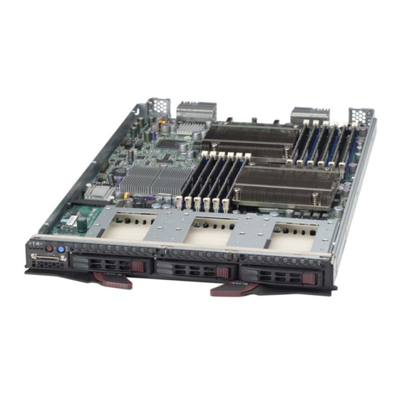
Chapter 4 Blade Module Features Figure 4-1. SBI-7426T-S3 Blade Module Front View This chapter describes the SBI-7426T-S3 blade module. Installation and maintenance should be performed by experienced technicians only. Figure 4-1 for a front view of the blade unit and Table 4-1 for its features. -
Page 32: Control Panel
SBI-7426T-S3 Blade Module User’s Manual Control Panel Each blade has a similar control panel (Figure 4-2) with power on/off button, a KVM connector, a KVM button and four LEDs on the top front of the unit. The numbers mentioned in... -
Page 33: Power Button
Chapter 4: Blade Module Features Power Button Each blade has its own power button so that individual blade units within the enclosure may be turned on or off independently of the others. Press the power button (#1) to turn on the blade server. The power LED (#3) will turn green. To turn off, press and hold the power button for >4 seconds and the power LED will turn orange. -
Page 34: Mainboard
SBI-7426T-S3 Blade Module User’s Manual Mainboard The mainboard of the SBI-7426T-S3 blade unit is a proprietary design, which is based on the Intel 5500 Tylersburg chipset. See Figure 4-4 for a block diagram of this chipset, Figure 4-3 for a view of the B8DT6 Mainboard and... -
Page 35: Figure 4-4. Intel 5500 Tylersburg Chipset Block Diagram
Chapter 4: Blade Module Features Table 4-4. B8DT6 Mainboard Layout Item Description LGA 1366 CPU1 Socket LGA 1366 CPU2 Socket DIMM Slots (see Figure 3-5: "12-Slot DIMM Numbering" on page 3-7 for details) 3 SAS2/SATA Hard Drive Bays InfiniBand Connectors (for InfiniBand cards) Gbx Connectors (for power and logic to backplane) ICH10R (South Bridge chip) Intel 5500 Tylersburg (North Bridge chip) -
Page 36: Jumpers
SBI-7426T-S3 Blade Module User’s Manual Jumpers The jumpers present on the mainboard are used by the manufacturer only; there are no jumpers used to configure the operation of the mainboard. CMOS Clear JBT1 is used to clear CMOS and will also clear any passwords. JBT1 consists of two... -
Page 37: Blade Unit Components
Chapter 4: Blade Module Features Blade Unit Components Figure 4-5. Exploded View of SBI-7426T-S3 Blade Module Main components of the SBI-7426T-S3 blade module are shown in Figure 4-5 described in Table 4-5. Table 4-5. Main Components of SBI-7426T-S3 Blade Module... -
Page 38: Memory Support
SBI-7426T-S3 Blade Module User’s Manual Memory Support The SBI-7426T-S3 blade module supports up to 96 GB/24 GB of VLP ECC Registered/ Unbuffered ECC DDR3-1333/1066/800 SDRAM in twelve DIMM sockets. See Section 3-5 for further details on mainboard memory installation. Hard Disk Drives The SBI-7426T-S3 blade unit accommodates up to three 2.5"... -
Page 39: Chapter 5 Raid Setup Procedure
Chapter 5 RAID Setup Procedure Each SBI-7426T-S3 blade module supports three hard drives, which may be used to create a RAID array. For the blade’s B8DT6 mainboard when using SATA drives, use the BIOS setup to configure for either the Intel or Adaptec RAID controller and utility: use the Intel driver for Windows and the Adaptec driver for Linux - both are included on the CD that ships with the system. -
Page 40: Bios Configuration Utilities
SAS drives, use the LSI MegaRAID Software Configuration Utility found on your system’s CD-ROM disc for your RAID setup For details and instructions on the use of these utilities see the SuperMicro website at http://www.supermicro.com/support/manuals/ for these RAID Installation Guides. -
Page 41: Bios Setup
Chapter 5: RAID Setup Procedure BIOS Setup Use the BIOS setup when using SATA drives to configure for either the Intel or Adaptec RAID Utility and to set other RAID options. The BIOS setup procedure is shown below. Chapter 6 for information on using your system’s BIOS setup. -
Page 42: Figure 5-2. Ide Configuration Screen - Configure Raid Drives
SBI-7426T-S3 Blade Module User’s Manual 2. In the IDE Configuration screen that appears (Figure 5-2), select the SATA drives you wish to configure as RAID drives. For each drive, select the C SATA# ONFIGURE menu option and select the RAID option for it. -
Page 43: Figure 5-3. Selecting Max Ports Option
Chapter 5: RAID Setup Procedure 3. In the changed IDE C screen, select the M SATA# option ONFIGURATION ORTS ON and set your ports selection (Figure 5-3). Figure 5-3. Selecting Max Ports Option... -
Page 44: Figure 5-4. Selecting Raid Utility
SBI-7426T-S3 Blade Module User’s Manual 4. For the RAID ID Support menu option (Figure 5-4), select either the Intel or Adaptec utility for configuring your RAID configuration. Figure 5-4. Selecting RAID Utility... -
Page 45: Figure 5-5. Enabling Hot Plug
Chapter 5: RAID Setup Procedure 5. The last option is for enabling or disabling Hot Plug support for your RAID configuration using the H menu option (Figure 5-5). Figure 5-5. Enabling Hot Plug... -
Page 46: Figure 5-6. Exit Bios Setup
SBI-7426T-S3 Blade Module User’s Manual 6. Press the Esc key once to exit the IDE C screen and go to the E ONFIGURATION menu in the BIOS setup. From the Exit menu, select S HANGES AND confirm your RAID configuration changes and exit the BIOS Setup (Figure 5-6). -
Page 47: Figure 5-7. Screen Message
Chapter 5: RAID Setup Procedure 7. Your system will reboot. When the reboot displays the screen message in Figure 5-7 press C -A to bring up the RAID Configuration Utility you chose in step 4 (Intel or Adaptec). Figure 5-7. Screen Message... - Page 48 SBI-7426T-S3 Blade Module User’s Manual Notes 5-10...
-
Page 49: Chapter 6 Bios
NOTE: Due to periodic changes to the BIOS, some settings may have been added or deleted and might not yet be recorded in this manual. Please refer to http://www.supermicro.com/products/SuperBlade/module/ web site for further details on BIOS setup and the BIOS menus for your SuperBlade blade module. -
Page 50: Bios Updates
SBI-7426T-S3 Blade Module User’s Manual BIOS Updates It may be necessary to update the BIOS used in the blade modules on occasion. However, it is recommended that you not update BIOS if you are not experiencing problems with a blade module. -
Page 51: Running Setup
Chapter 6: BIOS 3. Go to the V menu and select F IRTUAL EDIA LOPPY MAGE PLOAD 4. B or O to locate the *.img file on your desktop and select it. ROWSE 5. Press the U button and wait a few seconds for the image to upload to the PLOAD CMM. -
Page 52: Main Bios Setup
SBI-7426T-S3 Blade Module User’s Manual Main BIOS Setup All Main Setup options are described in this section. Use the U arrow keys to move among the different settings in each menu. Use the L arrow keys to change the options for each setting. -
Page 53: Advanced Setup
Chapter 6: BIOS Table 6-1. Main BIOS Setup Menu Options Menu Option Description To set the system date and time, key in the correct information in the appropriate System Time fields. Then press the <Enter> key to save the data. Using the arrow keys, highlight the month, day and year fields, and enter the System Date correct data for the system date. -
Page 54: Table 6-2. Advanced Setup Menu Options
SBI-7426T-S3 Blade Module User’s Manual The items with a triangle beside them are sub-menus that can be accessed by highlighting the item and pressing <E >. Options for PIR settings are displayed by NTER highlighting the setting option using the arrow keys and pressing <E >. -
Page 55: Table 6-3. Cpu And Clock Configuration Sub-Menu
Chapter 6: BIOS Table 6-3. CPU and Clock Configuration Sub-menu Menu Option Description Sets the ratio between CPU core clock and the FSB frequency. The default setting depends upon the type of CPU installed on the mainboard. The default setting for the CPU installed in your mainboard is 18. Press + or - on your Ratio CMOS Setting keyboard to change this value. -
Page 56: Table 6-5. Pcipnp Configuration Sub-Menu
SBI-7426T-S3 Blade Module User’s Manual Table 6-4. IDE Configuration Menu (Continued) Menu Option Description This setting allows you to select either the Intel or A RAID Configuration DAPTEC RAID ID Support Utility to be used for configuring your RAID setup. This setting is only available when RAID is selected for SATA#1 Configuration. -
Page 57: Table 6-6. Superio Configuration Sub-Menu
Chapter 6: BIOS Table 6-6. SuperIO Configuration Sub-menu Menu Option Description This option specifies the base I/O port address and the Interrupt Request address of Serial Port 1. Select Disabled to prevent the serial port from accessing any system resources. When this option is Disabled, the serial port Serial Port1 Address physically becomes unavailable. - Page 58 SBI-7426T-S3 Blade Module User’s Manual Table 6-7. Chipset Configuration Sub-menu (Continued) Menu Option Description Serial Debug This feature specifies what level of debug messages to display. The default Message Level option is None. North Bridge This sub-menu configures North Bridge features Configuration This feature works with Intel’s I/O Acceleration Technology (AT) to accelerate the...
-
Page 59: Table 6-8. Acpi Configuration Sub-Menu
Chapter 6: BIOS Table 6-7. Chipset Configuration Sub-menu (Continued) Menu Option Description This option allows you to specify what your system will do when power is Restore on AC restored after an AC power loss. Options include Power Off, P OWER Power Loss TATE... -
Page 60: Table 6-9. Ahci Configuration Sub-Menu
SBI-7426T-S3 Blade Module User’s Manual Table 6-9. AHCI Configuration Sub-menu Menu Option Description This option enables AHCI BIOS support on your system. Options include AHCI BIOS Support Enabled and D ISABLED This sets the timeout time in seconds for AHCI CD/DVD boot drives. Some SATA AHCI CD/DVD Boot CD/DVD drives in AHCI mode need to wait longer than others. - Page 61 Chapter 6: BIOS Table 6-11. IPMI Configuration Sub-menu (Continued) Menu Option Description This option allows you to clear the BMC system log. Select Cancel to keep the BMC system log and Ok with the <E > key to clear the BMC system log. NTER Clear BMC System WARNING: Any cleared information is unrecoverable.
-
Page 62: Table 6-12. Mps Configuration Sub-Menu
SBI-7426T-S3 Blade Module User’s Manual Notes Table 6-12. MPS Configuration Sub-menu Menu Option Description This option allows you to select the MPS revision used for your system. Options MPS Revision include 1.1 and 1.4. Table 6-13. PCI Express Configuration Sub-menu... -
Page 63: Security
Chapter 6: BIOS Table 6-16. System Health Monitor Sub-menu Menu Option Description This screen displays information about your system’s health and includes the following health information: • CPU Temperatures (for both CPUs) • System Temperature • CPU Vcore (for both CPUs) •... -
Page 64: Table 6-17. Security Menu Options
SBI-7426T-S3 Blade Module User’s Manual Choose Security from the AMI BIOS Setup Utility main menu with the arrow keys to bring up the S menu (Figure 6-3). Security setting options are displayed ECURITY ETUP by highlighting the setting using the arrow keys and pressing <E >. -
Page 65: Boot
Chapter 6: BIOS Boot Figure 6-4. Boot Setup Menu Choose Boot from the AMI BIOS Setup Utility main menu with the arrow keys to bring up the B menu (Figure 6-4). Security setting options are displayed by ETUP highlighting the setting using the arrow keys and pressing <E >. - Page 66 SBI-7426T-S3 Blade Module User’s Manual Table 6-18. Boot Setup Menu Options (Continued) Menu Option Description AddOn ROM This option allows you to set the display mode for Option ROM. Options include Display Mode Force BIOS or K URRENT Use this option to select a Power-on state for Numlock during boot-up. Options...
-
Page 67: Exit
Chapter 6: BIOS Exit Figure 6-5. Exit Setup Menu Choose E from the AMI BIOS Setup Utility main menu with the arrow keys to display the E menu (Figure 6-5). All Exit BIOS settings are described in Table 6-19 ETUP below. -
Page 68: Hardware Health Information
‘Temperature Tolerance’ is so temperature management can be undertaken. Supermicro uses this featue in its mainboard’s by assigning a temperature status to certain thermal conditions in the processor (Low, Medium and High). This makes it easier for you to understand the CPU’s temperature status, rather than by simply seeing... -
Page 69: System Temperature
Chapter 6: BIOS NOTE: The system may shut down if this high level continues for a long period in order to prevent damage to the CPU. System Temperature The system temperature is displayed (in degrees Celsius and Fahrenheit) as it is detected by the BIOS. - Page 70 SBI-7426T-S3 Blade Module User’s Manual Notes 6-22...
-
Page 71: Appendix A Bios Post Codes
Appendix A BIOS POST Codes BIOS POST Messages During the Power-On Self-Test (POST), the BIOS will check for problems. If a problem is found, the BIOS will activate an alarm or display a message. The following is a list of such BIOS messages. - Page 72 SBI-7426T-S3 Blade Module User’s Manual Table A-1. BIOS POST Messages (Continued) BIOS Message Description Previous POST did not complete successfully. POST loads default values and offers to run Setup. If the failure was caused by incorrect values and they are not corrected, the next boot Previous boot incomplete - Default will likely fail.
-
Page 73: A-2 Bios Post Codes
Table A-1. BIOS POST Messages (Continued) BIOS Message Description Where nnnn is the amount of RAM in kilobytes successfully nnnn kB Extended RAM Passed tested. Where nnnn is the amount of system cache in kilobytes nnnn Cache SRAM Passed successfully tested. Where nnnn is the amount of shadow RAM in kilobytes nnnn kB Shadow RAM Passed successfully tested. -
Page 74: Recoverable Post Errors
SBI-7426T-S3 Blade Module User’s Manual Recoverable POST Errors When a recoverable type of error occurs during POST, the BIOS will display an POST code that describes the problem. BIOS may also issue one of the following beep codes: • One long and two short beeps – video configuration error •... - Page 75 Table A-2. Terminal POST Errors (Continued) Post Code Description 1-3-1-3 Test 8742 Keyboard Controller Auto size DRAM Initialize POST Memory Manager Clear 512 kB base RAM 1-3-4-1 RAM failure on address line xxxx* 1-3-4-3 RAM failure on data bits xxxx* of low byte of memory bus Enable cache before system BIOS shadow Test CPU bus-clock frequency Initialize Phoenix Dispatch Manager...
- Page 76 SBI-7426T-S3 Blade Module User’s Manual Table A-2. Terminal POST Errors (Continued) Post Code Description Test RAM between 512 and 640 kB Test extended memory Test extended memory address lines Jump to UserPatch1 Configure advanced cache registers Initialize Multi Processor APIC...
- Page 77 Table A-2. Terminal POST Errors (Continued) Post Code Description Build MPTABLE for multi-processor boards Install CD ROM for boot Clear huge ES segment register 1-2 Search for option ROMs. One long, two short beeps on check-sum failure Check for SMART Drive (optional) Shadow option ROMs Set up Power Management Initialize security engine (optional)
-
Page 78: Table A-3. Boot Block Flash Rom Terminal Post Errors
SBI-7426T-S3 Blade Module User’s Manual Table A-2. Terminal POST Errors (Continued) Post Code Description Initialize system error handler PnPnd dual CMOS (optional) Initialize note dock (optional) Initialize note dock late Force check (optional) Extended checksum (optional) Redirect Int 15h to enable remote keyboard... - Page 79 Table A-3. Boot Block Flash ROM Terminal POST Errors (Continued) Post Code Description Initialize video Initialize System Management Manager Output one beep Clear Huge Segment Boot to Mini DOS Boot to Full DOS If the BIOS detects error 2C, 2E, or 30 (base 512K RAM error), it displays an additional word-bitmap ( ) indicating the address line or bits that failed.
- Page 80 SBI-7426T-S3 Blade Module User’s Manual Notes A-10...
- Page 81 Disclaimer The products sold by Supermicro are not intended for and will not be used in life support systems, medical equipment, nuclear facilities or systems, aircraft, aircraft devices, aircraft/emergency communication devices or other critical systems whose failure to perform be reasonably expected to result in significant injury or loss of life or catastrophic property damage.
- Page 82 SBI-7426T-S3 Blade Module User’s Manual...