
Related Manuals for Runco VX-5000d


Summary of Contents for Runco VX-5000d
- Page 1 ’ WNER PERATING ANUAL VX-5000d Projector & DHD™ Controller Widescreen Digital Light Processing™ Projector & DHD™ Video Controller with Vivix™ Technology...
-
Page 3: Table Of Contents
Table of Contents Introduction ........................3 Warnings and Safety Precautions.................. 4 Warning ........................5 Safety Tips........................5 Limited Warranty......................6 Features and Benefits ....................8 Projector Description ...................... 9 Top View ........................9 Input Panel ........................9 Ceiling Mount Dimensions.................... 10 Horizontal and Vertical Lens Shift................ -
Page 5: Introduction
The new VX-5000d builds off of the versatility of the VX-5000ci DLP by employing Runco's 3rd Generation engineering practices. The GEN 3 features included with the VX-5000d are: motorized Reflectance Volume Regulation (RVR), digital video input with HDCP, 9-point Color Balance, and the contrast 16:9 HD2+ DMD (Digital Micro-Mirror Device) from Texas Instruments™. -
Page 6: Warnings And Safety Precautions
Warnings and Safety Precautions WARNING FCC Regulations state that any unauthorized changes or modifications to this equipment not expressly approved by the manufacturer could void the user's authority to operate this equipment. CAUTION: TO PREVENT FIRE OR SHOCK HAZARDS, DO NOT REMOVE COVER. DO NOT EXPOSE THIS UNIT TO RAIN OR MOISTURE. -
Page 7: Warning
Should the power cord become damaged in any way, please contact your Runco Dealer for a replacement cord. · Do not remove the cover of the Projector or DHD Controller for any reason. If any problems arise with the unit, please contact a Runco Dealer or Runco International for service. -
Page 8: Limited Warranty
PROVIDING WHEN INSTALLED AND CALIBRATED BY RUNCO AUTHORIZED PERSONNEL. RIGHTS, LIMITS AND EXCLUSIONS: Runco limits its obligations under any implied warranties under state laws to a period not to exceed the warranty period. There are no express warranties. Runco also excludes any obligation on its part for incidental or consequential damages related to the failure of this product to function properly. - Page 9 IMPORTANT: WARRANTY REGISTRATION: Please fill out and mail your warranty registration card. It is imperative that Runco knows how to reach you promptly if we should discover a safety problem or product update for which you must be notified.
-
Page 10: Features And Benefits
Features and Benefits The VX-5000d system is a very unique system and has many important features, including: • Native 1280 x 720, Single HD2+, 16:9 DMD™ Chip creates images with appropriate black levels in darkened scenes • DVI input allows digital connections for a richer pixel for pixel and unadjusted signal. -
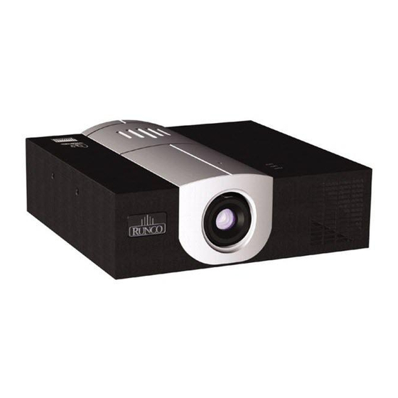
Page 11: Projector Description
Projector AC Power In DVI-I IN ComLink In (100-240 VAC) PC INPUT Connect the ComLink cable from the DHD Controller here RGB Input Service Reset (from DHD Controller) To be used by Authorized Runco Service Technicians... -
Page 12: Ceiling Mount Dimensions
Ceiling Mount Dimensions Front View 12.241 Lens Offset from the logo side of Projector 4.315 5.960 10.979 11.227 20.870 Side View 8.935 1.015 1.645 12.500 Feet Height Bracket Height Bottom View 6.500 (2X) 8.796 27.804 10.750 (2X) 11.400 Center of Bracket 26.304 14.004 15.000 (2X) -
Page 13: Horizontal And Vertical Lens Shift
Horizontal Vertical and Lens Shift Vertical Lens Shift (Up or Down) 150% Height Lens Shift (1.5 x H) 100% Height Lens Shift (1.0 x H) 12.500 10.750 1.645 1.015 8.796 50% Height Lens Shift Screen Center (0.5 x H) 10.580 Base plate to center of lens Approx. -
Page 14: Lens Shift Range
Lens Shift Range The examples show the location of the image position in the lens. The lens can be shifted within the shaded area as shown using the normal projection position as a starting point. Note: If lens is shifted in two directions combined, max. range in either direction cannot be obtained due to rounded off area near edge of lens. - Page 15 Example: 56" x 100" Screen Lens Option 3: Throw Distance 2.76 - 4.85 x Width of Screen TD = 276" to 485" lens to screen When only Vertical or only Horizontal shift is used: 0.95 X 56" = 53.2" up or down Maximum Vertical Shift = 95% of screen height (.95 x height) 0.52 X 100"...
- Page 16 Lens Option 6: Throw Distance 0.8 Fixed x Width of Screen Example: 56" x 100" Screen When only Vertical or only Horizontal Shift is used: TD = 8" lens to screen Maximum. Vertical Shift = 15% of screen height (.15 x height) Maximum Horizontal Shift = 10% of screen width (.1 x width) 0.15 X 56"...
-
Page 17: Lens Adjustments
100' of range to the projector for long throw dis- tances. The IR Receiver for the lens motor assembly is located on the projector behind the front RUNCO logo cover. Rotate the logo cover 90 degrees as shown above to reveal the 0.5" diameter IR Receiver opening. -
Page 18: Prontoneo Remote Control Description
ProntoNeo Remote Control Description Sending LED Learning Eye Serial Port for Communicating with a PC LCD Touch Screen Backlight Button to activate the display Page Up Button Page Down Button 2 Content Specific Buttons Mode Button to switch to Device Button another mode to activate the Device Overview... -
Page 19: Battery Installation And Replacement
Battery Installation and Replacement Insert the 3 AA batteries, making sure to set them in with the proper polarity. 1. Press and open the back cover. 2. Align the batteries according to the (+) and (-) indication inside the case. 3. -
Page 20: Prontoneo Remote Control Usage
Projector and send you to to select your Aspect Ratio. the Aspect Ratio or Source screen. Menu Screen: Focus & Zoom Screen: Runco Screen This screen will access the This screen allows you to Menu. access the focus and zoom feature. -
Page 21: Dhd Controller Description
DHD Controller Description Front Panel RUNCO ICON When the Red light is displayed the unit is in Standby, when Blue light is displayed the unit is On. 2. POWER BUTTON Press once to toggle on from Standby mode to On mode, a second time to place into Standby mode. -
Page 22: Rear Panel
INPUTS: devices. 3. DVI 1 (Digital) 12. RS-232 OUT (RJ-11 Connector) DVI input #1, HDCP compliant. Comlink connection to VX-5000d projector. 4. DVI 2 (Digital) 13. IR DVI input #2, HDCP compliant. Wired input from an external remote control. 5. HD 1 (Analog BNC connectors) 14. -
Page 23: Quick Set-Up Guide
While there are many different ways to connect your source equipment to your Controller, the examples shown above are the most common and are recommended by Runco. • COMPOSITE VIDEO INPUT: Composite video is the most common type of signal used, but is also the lowest in picture qual- ity. - Page 24 Now that your DHD Controller has been installed, it’s time to get it configured for use in your system. The VX- 5000d/DHD is defaulted for RGBHV interface between the DHD controller and the VX-5000d projector. Superior picture quality will be obtained if you connect the two units together with a DVI cable. Please follow the proce-...
-
Page 25: Overall Functional Description
The DHD Controller tells the Projector to turn on or off, controls its brightness, contrast, color tempera- ture and more. All of this is accomplished by Runco's unique ComLink, which is the transfer of informa- tion between the DHD Controller and the Projector via their ComLink ports on a CAT5 cable (or similar) with RJ-11 ends. -
Page 26: Menu Description And Navigation
'looped' directly to the output. When pass-through is the selected source, pressing MENU will not automatically select the last selected input before Pass-through was selected. If you wish to choose another source, Runco recommends using the direct access buttons to select the desired source as opposed to pressing MENU. -
Page 27: Aspect Ratio
Aspect Ratio provides selection of one of four aspect ratios: Anamorphic, Standard 4:3, Letterbox or VirtualWide. To select an aspect ratio via the main menu, press either the up and down buttons on the remote or front panel, highlight ASPECT RATIO and press ENTER. The aspect ratio menu will then appear with the four choices;... - Page 28 CONTRAST adjusts the white level of the image. For Fixed-pixel displays, adjust contrast until there is a distinct definition between the two brightest bars. NOTE: For best results, Runco recommends that CONTRAST be set to '0' or very close to it. (see below)
- Page 29 SHARPNESS adjusts the amount of high-frequency detail in the image. This can be adjusted to the preference of the user. Keep in mind that when SHARPNESS is decreased, fine details in the image will become 'soft'; when it is increased, fine details will become sharper but will also make the picture appear 'noisy' if adjusted too high.
-
Page 30: Lens Replacement Procedure
Lens Replacement Procedure NOTE: Lens Replacement is normally performed at Runco. The only time this procedure will be performed in the field is if there is a change or mistake. Item 1 : Front of Lens Item 2 : Motor Assembly Item 3 : 9/64 Hex Screw (qty. - Page 31 Step 1: Remove the Front Cover (Item 5) by loosening #2 Phillips screw below lens. Figure 1 Step 2: Locate and unplug the Motor Assembly Connector (Item 4); remember wire routing for the new lens. Figure 2 Step 3: Locate the six 9/64 Hex Mounting Screws (Item 3).
- Page 32 Make sure to route the wire harness (Item 4) in original position and away from moving lens stages and Motor Assembly to prevent unexpected disconnect or lens damage. --See Figure 6 Below-- Figure 5 VX-5000d Projector (front view) with Lens Assembly completely removed. Figure 6...
-
Page 33: Basic Troubleshooting Tips
The following is a basic troubleshooting guide that can assist you in resolving typical problems may result in normal operation. If you have encountered problems that are not listed in this guide, please contact your Runco dealer for assistance. PROBLEM... - Page 34 PROBLEM POSSIBLE CAUSE SOLUTION The image appears too · Brightness is set too high. · Turn down the BRIGHTNESS 'washed out', or the darkest · The DVD player may be set level on the Controller. If possi- areas of the image appear too for too high of a brightness ble, use a PLUGE pattern to set bright.
-
Page 35: Rs-232 Communications
RS-232 Communications General Information Baud rate: 19200 (fixed) Bits: 8 No Parity All protocol in ASCII format RS-232 input connector pin numbers: TxD= Pin# 2, RxD= Pin# 3, GnD= Pin# 5 Command format (single command): command value (i.e. brightness 100). NOTE: A space (not an underscore) or comma may be used between the command and its value. -
Page 36: Rs-232 Commands
RS-232 Commands COMMAND PARAMETER Value stored? DESCRIPTION (min/max) POWER Turns DHD On and Off Turns DHD Controller on Turns DHD Controller off COMPOSITE Selects the Composite video input SVIDEO1 Selects the S-Video 1 input SVIDEO2 Selects the S-Video 2 input COMPONENT Selects the Component input Selects the RGB HD 1 input... - Page 37 COMMAND PARAMETER Value stored? DESCRIPTION (min/max) !STORE Stores the current set of values (all values) into non-volatile memory !RESTORE Restores the stored values !FACTORY Restores all values to factory default levels !STATUS Asks the Controller to provide the hardware information, current values and system status to the automation system !RESTART...
- Page 38 VX-5000d Projector Dimensions Top View Side View 26.304 Front View Bottom View 24.069 8.185 1.015 2.235 Lens Dimensions Lens Factor Lens Diameter Lens Distance from Chassis 1.57 - 1.95 4.717 1.492 1.95 - 2.74 5.472 Flush with Chassis 2.76 - 4.85 4.474...
- Page 39 DHD Controller Dimensions Front Panel 3.5" 17.5" Top Panel 11"...
-
Page 40: Dimensions
Specifications VX-5000d Projector: Projector Type: Digital Light Processing™ (DLP™), Single HD2+ DMD™ Chip Native Resolution: 1280 x 720 (Designed for 16:9 screens only) Aspect Ratios: Determined by supplied processor Video Standards: NTSC, PAL DTV Compatibility: 480p, 720p, 1080i Scan Frequency:... - Page 41 DHD Controller: Aspect Ratios: Anamorphic, Letterbox, VirtualWide™, 4:3 Input standards: NTSC / PAL Output resolution: 720P Outputs: (1) HD - R (Pr), G (Y), B (Pb), H, V; (1) DVI w/HDCP Inputs: (1) Composite; (2) S-Video; (1) Component; (2) HD - R (Pr), G (Y), B (Pb), H, V;...
- Page 43 RUMA-010875 rev 9-20-04 v2 • • • • • Runco International 2900 Faber Street Union City, CA 94587 ph (510) 324-7777 fax (510) 324-9300 www.runco.com...