Table of Contents
Advertisement
Quick Links
Advertisement
Table of Contents

Related Manuals for Supero SuperWorkstation 5037A-I


Summary of Contents for Supero SuperWorkstation 5037A-I
- Page 1 UPER ® uper orkstation 5037A-I USER’S MANUAL...
- Page 2 The information in this User’s Manual has been carefully reviewed and is believed to be accurate. The vendor assumes no responsibility for any inaccuracies that may be contained in this document, makes no commitment to update or to keep current the information in this manual, or to notify any person or organization of the updates.
-
Page 3: About This Manual
903B chassis. Chapter 2: Server Installation This chapter describes the steps necessary to set up the SuperWorkstation 5037A-I and to check out the server configuration prior to powering-up the system. If your system was ordered without processor and memory components, this chapter will refer you to the appropriate sections of the manual for their installation. - Page 4 5037A-I User's Manual Chapter 5: Advanced Motherboard Setup Chapter 5 provides detailed information on the X9SRA motherboard, including the locations and functions of connections, headers and jumpers. Refer to this chapter when adding or removing processors or main memory and when reconfiguring the motherboard.
- Page 5 Preface Notes...
-
Page 6: Table Of Contents
5037A-I User's Manual Table of Contents Chapter 1 Introduction Overview ......................1-1 Motherboard Features ..................1-2 Processors ...................... 1-2 Memory ......................1-2 SATA ......................1-2 PCI Expansion Slots ..................1-2 Onboard Controllers/Ports ................1-2 Chassis Features .................... 1-2 System Power .................... - Page 7 Table of Contents Cautions ......................5-1 Unpacking ....................... 5-2 Motherboard Installation .................. 5-2 Connecting Cables ..................5-3 Connecting Data Cables ................. 5-3 Connecting Power Cables ................5-3 Connecting the Control Panel ................. 5-3 I/O Ports ......................5-4 Processor and Heatsink Installation..............5-5 Installing an LGA 2011 Processor ..............
- Page 8 5037A-I User's Manual Removing and Installing Optional 2.5" Hard Drives ........6-11 Power Supply ....................6-13 Chapter 7 BIOS Introduction ...................... 7-1 Starting BIOS Setup Utility ................7-1 How To Change the Configuration Data ............7-1 How to Start the Setup Utility ................. 7-2 Main Setup ......................
-
Page 9: Chapter 1 Introduction
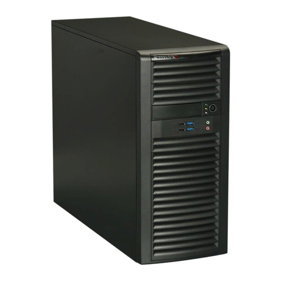
Chapter 1 Introduction Overview The 5037A-I is a high-end workstation comprised of two main subsystems: the SC732D4-903B mid-tower/4U chassis and the X9SRA Intel® Xeon® processor motherboard. Please refer to our web site for information on operating systems that have been certified for use with the SuperWorkstation 5037A-I (www.supermicro. -
Page 10: Motherboard Features
5037A-I User's Manual Motherboard Features At the heart of the SuperWorkstation 5037A-I lies the X9SRA, a single processor motherboard based on the Intel® C600 series chipset. Below are the main features of the X9SRA. (See Figure 1-1 for a block diagram of the chipset). -
Page 11: System Power
2.5" hard drives. Front Control Panel The control panel on the 5037A-I provides you with system monitoring and control. LEDs indicate system power, HDD activity, network activity, overheat conditions and power supply failure. A main power button and a system reset button are also included. -
Page 12: System Block Diagram
5037A-I User's Manual Figure 1-1. Intel C600 Chipset: System Block Diagram Note: This is a general block diagram. Please see Chapter 5 for details. X9SRA #0-8 #0-4 #0-7 VR12 #0-3 #0-6 6 PHASE #0-2 #0-5 #0-1 Sandybridge-EP 8 SNB CORE... -
Page 13: Contacting Supermicro
Chapter 1: Introduction Contacting Supermicro Headquarters Address: Super Micro Computer, Inc. 980 Rock Ave. San Jose, CA 95131 U.S.A. Tel: +1 (408) 503-8000 Fax: +1 (408) 503-8008 Email: marketing@supermicro.com (General Information) support@supermicro.com (Technical Support) Web Site: www.supermicro.com Europe Address: Super Micro Computer B.V. Het Sterrenbeeld 28, 5215 ML 's-Hertogenbosch, The Netherlands Tel:... - Page 14 5037A-I User's Manual Notes...
-
Page 15: Chapter 2 Installation
Installation Overview This chapter provides a quick setup checklist to get your SuperWorkstation 5037A-I up and running. Following these steps in the order given should enable you to have the system operational within a minimum amount of time. This quick setup assumes that your system has come to you with the processor and memory preinstalled. -
Page 16: Choosing A Setup Location
5037A-I User's Manual Choosing a Setup Location • Leave enough clearance in front of the rack to enable you to open the front door completely (~25 inches) and approximately 30 inches of clearance in the back of the rack to allow for sufficient airflow and ease in servicing. -
Page 17: Chapter 3 System Interface
System Interface Overview The control panel on the 5037A-I has several LEDs and two buttons. There are also two LEDs on each hard drive carrier. These LEDs keep you constantly informed of the overall status of the system and the activity and health of specific components. -
Page 18: Control Panel Leds
5037A-I User's Manual Control Panel LEDs The control panel located on the front of the SC732D4-903B chassis has three LEDs that provide you with critical information related to different parts of the system. This section explains what each LED indicates when illuminated and any corrective action you may need to take. -
Page 19: Chapter 4 System Safety
System Safety Electrical Safety Precautions Basic electrical safety precautions should be followed to protect yourself from harm and the SuperWorkstation 5037A-I from damage: • Be aware of the locations of the power on/off switch on the chassis as well as the room's emergency power-off switch, disconnection switch or electrical outlet. -
Page 20: General Safety Precautions
General Safety Precautions Follow these rules to ensure general safety: • Keep the area around the SuperWorkstation 5037A-I clean and free of clutter. • The 5037A-I weighs approximately 29.5 lbs (13.38 kg.) when fully loaded. When lifting the system, two people at either end should lift slowly with their feet spread out to distribute the weight. -
Page 21: Esd Precautions
Chapter 4: System Safety • After accessing the inside of the system, close the system back up and secure it to the rack unit with the retention screws after ensuring that all connections have been made. ESD Precautions Electrostatic discharge (ESD) is generated by two objects with different electrical charges coming into contact with each other. -
Page 22: Operating Precautions
5037A-I User's Manual Operating Precautions Care must be taken to assure that the chassis cover is in place when the system is operating to assure proper cooling. Out of warranty damage to the system can occur if this practice is not strictly followed. -
Page 23: Chapter 5 Advanced Motherboard Setup
Chapter 5: Advanced Serverboard Setup Chapter 5 Advanced Motherboard Setup This chapter covers the steps required to install the X9SRA motherboard into the chassis, connect the data and power cables and install add-on cards. All mother- board jumpers and connections are also described. A layout and quick reference chart are included in this chapter for your reference. -
Page 24: Unpacking
5037A-I User's Manual Unpacking The motherboard is shipped in antistatic packaging to avoid electrical static dis- charge. When unpacking the board, make sure the person handling it is static protected. Motherboard Installation This section explains the first step of physically mounting the X9SRA into the SC732D4-903B chassis. -
Page 25: Connecting Cables
Chapter 5: Advanced Serverboard Setup Connecting Cables Now that the motherboard is installed, the next step is to connect the cables to the board. These include the data (ribbon) cables for the peripherals and control panel and the power cables. Connecting Data Cables The cables used to transfer data from the peripheral devices have been carefully routed to prevent them from blocking the flow of cooling air that moves through the... -
Page 26: I/O Ports
5037A-I User's Manual Figure 5-1. Control Panel Header Pins Ground Power On LED LED VCC HDD LED LED VCC NIC1 LED LED VCC NIC2 LED LED VCC OH/Fan Fail LED LED VCC Power Fail LED LED VCC #3 - 4 Reset Button... -
Page 27: Processor And Heatsink Installation
Chapter 5: Advanced Serverboard Setup Processor and Heatsink Installation Caution: When handling the processor package, avoid placing direct pressure on the label area of the fan. Notes: • Always connect the power cord last and always remove it before adding, re- moving or changing any hardware components. - Page 28 5037A-I User's Manual 3. With the lever labeled 'Close 1st' fully retracted, gently push down on the 'Open 1st' lever to open the load plate. Lift the load plate to open it completely. Gently push 4. Using your thumb and the index...
- Page 29 Chapter 5: Advanced Serverboard Setup Caution: You can only install the CPU to the socket in one direction. Make sure that the CPU is properly inserted into the socket before closing the load plate. If it doesn't close properly, do not force it as it may damage your CPU. Instead, open the load plate again and double-check that the CPU is aligned properly.
-
Page 30: Installing A Cpu Heatsink
5037A-I User's Manual Installing a CPU Heatsink Caution: Remove the power cord before installing heatsinks. Do not reconnect it until the installation is completed. See http://www.supermicro.com/about/policies/ safety_information.cfm. 1. Do not apply any thermal grease to the heatsink or the CPU die; the required amount has already been applied. -
Page 31: Removing The Heatsink
Chapter 5: Advanced Serverboard Setup Removing the Heatsink Caution: We do not recommend that the CPU or the heatsink be removed. How- ever, if you do need to uninstall the heatsink, please follow the instructions below to uninstall the heatsink to prevent damage done to the CPU or the CPU socket. Additional warnings and cautions can be found on the Supermicro Web site at http:// www.supermicro.com/about/policies/safety_information.cfm. -
Page 32: Installing Memory Modules
5037A-I User's Manual Installing Memory Modules Note: Check the Supermicro Web site for recommended memory modules. CAUTION Exercise extreme care when installing or removing DIMM modules to prevent any possible damage. Press down the release tabs Installing and Removing DIMMs 1. -
Page 33: Memory Support
Chapter 5: Advanced Serverboard Setup Memory Support The X9SRA supports up to 256 GB of 1600/1066/1333/1600 MHz ECC/Non-ECC DDR3 DIMMS in eight memory slots. For the latest memory updates, please refer to the product page on the Supermicro Web site. Order of Populating DIMM Slots For memory to work properly, follow the table below for the correct order of populat- ing the DIMM slots. -
Page 34: Adding Pci Add-On Cards
5037A-I User's Manual Adding PCI Add-On Cards The 5037A-I can accommodate standard size add-on cards populated in all slots on the X9SRA motherboard. Installing an Add-on Card 1. Begin by removing the PCI slot shield for the slot you wish to populate. -
Page 35: Motherboard Details
Chapter 5: Advanced Serverboard Setup Motherboard Details Figure 5-4. X9SRA Layout FAN 5 USB 6/7 USB3.0 0/1 USB 4/5 JKBMS1 USB 2/3 HD AUDIO LAN2 LAN1 JPAC1 JSPDIF OUT JI2C1 JSPDIF IN JFPAUDIO USB 0/1 AUDIO FP JUSB45 JI2C2 JAUDIO1 HD AUDIO JSTBY JPAC1:AUDIO... - Page 36 5037A-I User's Manual Motherboard Headers/Connectors Connector Description AUDIO FP Front Panel Audio Header COM1, COM2 COM1 & COM2 Serial Port Headers USB 8/9, USB 10/11, USB 12/13 USB 2.0 Headers for front panel access JUSB2/3 (USB 3.0) USB 3.0 Header for USB 2/3 USB 0/1, USB 2/3, USB 4/5, USB 6/7 Back Panel USB 2.0 Ports...
-
Page 37: Connector Definitions
Chapter 5: Advanced Serverboard Setup Connector Definitions ATX Power 24-pin Connector Pin Definitions (JPW1) ATX Main PWR (JPW1) and CPU Pin# Definition Pin # Definition PWR Connectors (JPW2) +3.3V +3.3V The 24 - pin main power connector -12V +3.3V (JPW1) is used to provide power to the motherboard. - Page 38 5037A-I User's Manual (Back_Panel) High Definition Audio (HD (BP) HD Audio Audio) Conn# Signal This motherboard features a 7.1+2 Channel High S/P DIF Out Definition Audio (HDA) codec that provides 10 Surround Out DAC channels. The HD Audio connections simul- CEN/LFE Out taneously supports multiple-streaming 7.1 sound...
- Page 39 Chapter 5: Advanced Serverboard Setup Power Button Power Button The connection for the power button Pin Definitions (JF1) is on pins 1 and 2 of JF1. The chas- Pin# Definition sis power button should be connected PW_ON here. See the table on the right for pin Ground definitions.
- Page 40 5037A-I User's Manual Power LED Power LED Pin Definitions (JF1) The Power LED connection is located on Pin# Definition pins 15 and 16 of JF1. Refer to the table LED VCC on the right for pin definitions. Ground...
- Page 41 Chapter 5: Advanced Serverboard Setup Legacy Wake-On-LAN Header (JSTBY) Wake-On-LAN Pin Definitions The onboard LANs (LAN1 and LAN2) Pin# Definition do not need WOL header to support its +5V Standby Wake-On-LAN function. We preserved Ground the legacy WOL header to provide con- Wake-up venience for some embedded customers who need internal power source from the...
- Page 42 5037A-I User's Manual Overheat/Fan Fail LED (JOH1 Overheat LED Pin Definitions The JOH1 header is used to connect an Pin# Definition LED to provide warnings of chassis over- 5vDC heat. This LED will also blink to indicate a OH Active fan failure.
- Page 43 Chapter 5: Advanced Serverboard Setup Front Accessible Audio Header 10-in Audio A 10-pin Audio header is located on Pin Definitions the motherboard at AUDIO FP. This Pin# Signal header allows you to connect the Microphone_Left chassis' front panel audio ports to the Audio_Ground motherboard.
-
Page 44: 5-10 Jumper Settings
5037A-I User's Manual 5-10 Jumper Settings Explanation of Jumpers To modify the operation of the mother- board, jumpers can be used to choose Connector between optional settings. Jumpers Pins create shorts between two pins to change the function of the connector. - Page 45 Chapter 5: Advanced Serverboard Setup LAN Port Enable/Disable (JPL2) GLAN Enable Jumper Settings Jumper JPL2 enables or disables LAN Pin# Definition Port 2 on the motherboard. See the table Enabled (default) on the right for jumper settings. The de- Disabled fault setting is pins 1-2 (Enabled).
- Page 46 5037A-I User's Manual ME Recovery (JPME1) ME Recovery Jumper Settings ME Recovery (JPME1) is used to enable Jumper Setting Definition or disable the ME Recovery feature of 1-2 (Default) Normal the motherboard. Install the jumper on pins 1-2 for normal operation. Install pins...
-
Page 47: 5-11 Onboard Indicators
Chapter 5: Advanced Serverboard Setup 5-11 Onboard Indicators LAN Port LEDs The LAN ports are located on the I/O back- Link LEDs (Green/Amber/Off) panel of the motherboard. Each Ethernet LED Color Definition LAN port has two LEDs. The yellow LED No Connection or 10 Mbps indicates activity, while the Link LED may Green... -
Page 48: 5-12 Sata Ports
5037A-I User's Manual 5-12 SATA Ports SATA Ports SATA/SAS Ports There are four (4) SATA 2.0 ports, two (2) Pin Definitions SATA 3.0 ports and an additional four (4) Pin# Signal SATA 2.0 ports located on SAS 0~3:... -
Page 49: 5-13 Installing Software
Chapter 5: Advanced Serverboard Setup 5-13 Installing Software After the hardware has been installed, you should first install the operating system and then the drivers. The necessary drivers are all included on the Supermicro CDs that came packaged with your motherboard. Driver/Tool Installation Display Screen Note: Click the icons showing a hand writing on paper to view the readme files for each item. - Page 50 BIOS. Any subsequent changes to these thresholds must be made within SuperDoctor, as the SuperDoctor settings override the BIOS settings. To set the BIOS temperature threshold settings again, you would first need to uninstall SuperDoctor. Supero Doctor III Interface Display Screen (Health Information) 5-28...
-
Page 51: Superdoctor Iii
Chapter 5: Advanced Serverboard Setup Supero Doctor III Interface Display Screen (Remote Control) Note: The SuperDoctor III program and User's Manual can be downloaded from the Supermicro Web site at http://www.supermicro.com/products/accessories/software/ SuperDoctorIII.cfm. For Linux, we recommend using SuperDoctor II. 5-29... -
Page 52: 5-14 Motherboard Battery
5037A-I User's Manual 5-14 Motherboard Battery Caution: There is a danger of explosion if the onboard battery is installed upside down, which will reverse its polarites (see Figure 5-5). This battery must be re- placed only with the same or an equivalent type recommended by the manufacturer (CR2032). -
Page 53: Chapter 6 Advanced Chassis Setup
Chapter 6: Advanced Chassis Setup Chapter 6 Advanced Chassis Setup This chapter covers the steps required to install components and perform simple maintenance on the SC732D4-903B chassis. Following the component installation steps in the order given will eliminate most common problems. If some steps are unnecessary, skip ahead to the step that follows. -
Page 54: Installation Instructions
5037A-I User's Manual Installation Instructions Removing the Power Cord Before performing any setup or maintenance on the chassis, use the following procedure to ensure that power has been removed disconnected from the system. Removing the Power Cord 1. Use the operating system to Power down the system, following the on-screen prompts. - Page 55 Chapter 6: Advanced Chassis Setup Figure 6-1. Chassis Front View Main Power USB Ports (2x USB 3.0 and 2x USB 2.0) Audio Microphone Eight SATA Drive Bays (Inside chassis interior)
-
Page 56: Front Control Panel
5037A-I User's Manual Front Control Panel The front control panel must be connected to the JF1 connector on the motherboard to provide you with system status and alarm indications. A ribbon cable has bundled these wires together to simplify this connection. -
Page 57: Removing The Chassis Side Covers
Chapter 6: Advanced Chassis Setup Removing the Chassis Side Covers Figure 6-3: Removing the Chassis Side Covers The SC732D4-900B features two removable side covers, allowing easy access to the chassis interior. Removing the Side Covers 1. Disconnect the chassis from any power souce. 2. -
Page 58: System Fans
5037A-I User's Manual System Fans One 12-cm chassis cooling fan provides air intake while another 12-cm exhaust fan expels hot air from the chassis. Both are low-noise fans that result in "Whisper-Quiet" operation (~28 dB). The fans should be connected to headers on the motherboard (see Chapter 5). - Page 59 Chapter 6: Advanced Chassis Setup Figure 6-4. Removing a Chassis Fan...
-
Page 60: Drive Installation
5037A-I User's Manual Drive Installation A total of eight SAS or SATA drives may be housed in the SC732D4-900B chassis. The drive IDs are preconfigured as 0 through 7 in order from bottom to top. Remove the side panel of the chassis to access these drives as described in Chapter Caution: Regardless of how many SATA drives are installed, all drive carriers must remain in the drive bays to promote proper airflow. - Page 61 Chapter 6: Advanced Chassis Setup Figure 6-6: Removing the Hard Drive Carrier from the Hard Drive Cage Release Tabs 4. Press the release tab on the side of the hard drive carrier which is to be removed from the hard drive cage. 5.
- Page 62 5037A-I User's Manual Figure 6-8: Installing the Hard Drive Carrier into the Hard Drive Cage Optional Screw 8. Insert the new hard drive into the hard drive carrier. 9. Insert the hard drive carrier into the hard drive cage, sliding it towards the back of the the hard drive cage until it clicks into a locked position.
-
Page 63: Removing And Installing Optional 2.5" Hard Drives
Chapter 6: Advanced Chassis Setup Removing and Installing Optional 2.5" Hard Drives Figure 6-9: Removing the 2.5" Hard Drives Thumb Screw The SC732D4-900B chassis must be powered-down before hard drives can be removed from the hard drive carriers. Removing and Installing 2.5" Hard Drives 1. - Page 64 5037A-I User's Manual Figure 6-10: Installing 2.5" Hard Drives 5. If a hard drive is already present, remove it by carefully pulling the sides of the hard drive carrier outward. 6. Remove the hard drive from the hard drive carrier.
-
Page 65: Power Supply
Chapter 6: Advanced Chassis Setup Power Supply The SC732D4-900B chassis includes a 900 Watt power supply. In the unlikely event that it becomes necessary to replace the power supply, follow the instructions below. Figure 6-11: Removing the Power Supply Power Supply Changing the Power Supply 1. - Page 66 5037A-I User's Manual Notes 6-14...
-
Page 67: Chapter 7 Bios
Chapter 7: BIOS Chapter 7 BIOS Introduction This chapter describes the AMI BIOS Setup Utility for the X9SRA motherboard series. The AMI ROM BIOS is stored in a Flash EEPROM and can be easily up- dated. This chapter describes the basic navigation of the AMI BIOS Setup Utility setup screens. -
Page 68: How To Start The Setup Utility
5037A-I User's Manual How to Start the Setup Utility Normally, the only visible Power-On Self-Test (POST) routine is the memory test. As the memory is being tested, press the <Delete> key to enter the main menu of the AMI BIOS Setup Utility. From the main menu, you can access the other setup screens. - Page 69 Chapter 7: BIOS System Overview: The following BIOS information will be displayed: System Time/System Date Use this option to change the system time and date. Highlight System Time or Sys- tem Date using the arrow keys. Enter new values through the keyboard. Press the <Tab>...
-
Page 70: Advanced Setup Configurations
5037A-I User's Manual Advanced Setup Configurations Use the arrow keys to select Boot Setup and hit <Enter> to access the submenu items: BIOS SETUP UTILTY Main Advanced Event Logs Security Boot Save & Exit System Boot Feature Setting. -
Page 71: Cpu Configuration
Chapter 7: BIOS 19 at boot and allow the drives that are attached to these host adaptors to function as bootable disks. If this item is set to Disabled, the ROM BIOS of the host adap- tors will not capture Interrupt 19, and the drives attached to these adaptors will not function as bootable devices. - Page 72 5037A-I User's Manual Active Processor Cores Set to Enabled to use a processor's Second Core and beyond. (Please refer to Intel's web site for more information.) The options are All, 1, 2, 3, 4, 5, 6 and 7.
- Page 73 Chapter 7: BIOS creating multiple "virtual" systems in one physical computer. The options are Enabled and Disabled. Note: If there is any change to this setting, you will need to power off and restart the system for the change to take effect. Please refer to Intel’s web site for detailed information.
-
Page 74: Chipset Configuration
5037A-I User's Manual Short duration power limit - During Turbo Mode, the system may exceed the processor's default power setting and exceed the Short Duration Power limit. By increasing this value, the processor can provide better performance for a short duration. - Page 75 Chapter 7: BIOS DIMM Configuration Memory Configuration This section displays memory status such as Current Memory Mode, Memory Speed, Mirroring and Sparing information. DIMM Information This feature displays information regarding the installed memory. Memory Mode The options are Independent, Mirroring, Lockstep and Sparing. Independent - All DIMMs are available to the operating system.
- Page 76 5037A-I User's Manual Patrol Scrub Patrol Scrubbing is a process that allows the CPU to correct correctable memory errors detected on a memory module and send the correction to the requestor (the original source). When this item is set to Enabled, the North Bridge will read and write back one cache line every 16K cycles, if there is no delay caused by internal processing.
-
Page 77: Sata Configuration
Chapter 7: BIOS Legacy USB Support This feature enables support for legacy USB devices. Select Auto to disable legacy support if USB devices are not present. Select Disable to have USB devices available only for EFI applicatioins. The options are Enabled, Disabled and Auto. - Page 78 5037A-I User's Manual SATA Mode This item selects the mode for the installed drives. The options are Disabled, IDE Mode, AHCI Mode and RAID Mode. The following are displayed depending on your selection: IDE Mode The following items are displayed when IDE Mode is selected:...
- Page 79 Chapter 7: BIOS SCU Configuration When this submenu is selected, the AMI BIOS automatically detects the presence of the SAS SCU Devices and displays the following items: Disable Storage Controller Unit (SCU) Devices Set this item to Enabled to activate the chipset's SCU devices. The options are Enabled and Disabled.
- Page 80 5037A-I User's Manual Maximum Read Request This feature selects the setting for the PCIE maximum Read Request size. The options are Auto, 128 Bytes, 256 Bytes, 512 Bytes, 1024 Bytes, 2048 Bytes, and 4096 Bytes. ASPM Support Set this item to the desired ASPM (Active State Power Management) level. The options are Disabled, Auto and Force L0s..
-
Page 81: Serial Port Console Redirection
Chapter 7: BIOS Serial Port 1 Settings / Serial Port 2 Settings This option specifies the base I/O port address and the Interrupt Request address of Serial Port 1 and Serial Port 2. Select Disabled to prevent the serial port from accessing any system resources. When this option is set to Disabled, the serial port becomes unavailable. -
Page 82: Hardware Health Configuration
5037A-I User's Manual Data Bits: 8 or 7 Parity: None, Even, Odd, Mark, or Space Stop Bits: 1 or 2 Flow Control: None or Hardware RTS/CTS VT-UTF8 Combo Key Support: Enabled or Disabled Recorder Mode: Disabled or Enabled... - Page 83 Chapter 7: BIOS system cooling. Select "Full Speed" to allow the onboard fans to run at full speed (of 100% Pulse Width Modulation Duty Cycle) for maximum cooling. This setting is recommended for special system configuration or debugging. Select "Standard" for the onboard fans to run at 50% of the Initial PWM Cycle in order to balance the needs between system cooling and power saving.
-
Page 84: Acpi Settings
5037A-I User's Manual Fan 1 ~ Fan 4, Fan A Speed This feature displays the fan speed readings from fan interfaces Fan1 through Fan4 and FanA. VCORE, 12V, VDIMM, 5VCC, CPU VTT, AVCC, 3.3VCC, VSB, VBAT This feature displays the current voltages of the above voltage monitors. - Page 85 Chapter 7: BIOS Pending operation Displays any TPM-related operation by the system. Pending operation The following are informational status messages that indicate the current TPM State: TPM Enabled Status TPM Active Status TPM Owner Status Intel® TXT (LT-SX) Configuration Intel TXT Initialization Intel TXT (Trusted Execution Technology) helps protect against software-based at- tacks and ensures protection, confidentiality and integrity of data stored or created...
-
Page 86: Event Logs
5037A-I User's Manual Event Logs BIOS SETUP UTILTY Main Advanced Event Logs Security Boot Save & Exit Press <Enter> to change the Change Smbios Event Log Settings Smbios Event Log Configuration. View Smbios Event Log : Select Screen ... - Page 87 Chapter 7: BIOS When Log is Full This option automatically clears the Event Log memory of all messages when it is full. The options are Do Nothing and Erase Immediately. Log System Boot Event This option toggles the System Boot Event logging to enabled or disabled. The options are Disabled and Enabled.
-
Page 88: Security Settings
5037A-I User's Manual Security Settings BIOS SETUP UTILTY Main Advanced Event Logs Security Boot Save & Exit Password Description Set Administrator Password If ONLY the administrator’s password is set, then this only limits access to Setup and is only asked for when entering Setup. -
Page 89: Boot
Chapter 7: BIOS Boot Use this feature to configure Boot Settings: BIOS SETUP UTILTY Main Advanced Event Logs Security Boot Save & Exit Sets the system boot order Boot Option Priorities Boot Option #1 [P5: XXX XXXXXXX ...] Boot Option #2 [IBA GE Slot 00C8 v.. -
Page 90: Save & Exit
5037A-I User's Manual Save & Exit Select the Exit tab from the BIOS Setup Utility screen to enter the Exit BIOS Setup screen. BIOS SETUP UTILTY Main Advanced Event Logs Security Boot Save & Exit Discard Changes and Exit... - Page 91 Chapter 7: BIOS Save As User Defaults To set this feature, select Save as User Defaults from the Exit menu and press <Enter>. This enables the user to save any changes to the BIOS setup for future use Restore User Defaults To set this feature, select Restore User Defaults from the Exit menu and press <En- ter>.
- Page 92 5037A-I User's Manual Notes 7-26...
-
Page 93: Appendix A Bios Error Beep Codes
Appendix A: POST Error Beep Codes Appendix A BIOS Error Beep Codes During the POST (Power-On Self-Test) routines, which are performed each time the system is powered on, errors may occur. Non-fatal errors are those which, in most cases, allow the system to continue with bootup. - Page 94 5037A-I User's Manual Notes...
-
Page 95: Appendix B Uefi Bios Recovery Instructions
UEFI BIOS Recovery Appendix B UEFI BIOS Recovery Instructions Caution: Do not upgrade the BIOS unless your system has a BIOS-related issue. Flashing the wrong BIOS can cause irreparable damage to the system. In no event shall Supermicro be liable for direct, indirect, special, incidental, or consequential damages arising from a BIOS update. - Page 96 X9SRA Motherboard Series User's Manual To perform UEFI BIOS recovery using a USB-attached device, follow the instruc- tions below. 1. Using a different machine, copy the "Super.ROM" binary image file into the disc Root "\" Directory of a USB device or a writeable CD/DVD. Note: If you cannot locate the "Super.ROM"...
- Page 97 UEFI BIOS Recovery Aptio Setup Utility - Copyright (C) 2011 American Megatrends, Inc. Recovery WARNING! System rmware is being updated. Keyboard is locked. DO NOT TURN THE POWER OFF!!! Once rmware update is completed press any key to reboot the system Flash update progress Select Screen Select Item...
- Page 98 X9SRA Motherboard Series User's Manual Note: Do not interrupt this process until BIOS flashing is completed. After seeing the message that BIOS update is completed, unplug the AC power cable to clear CMOS, and then plug in the AC power cable to power on the system.
-
Page 99: Appendix C System Specifications
Appendix D: System Specifications Appendix C System Specifications Processors Intel Xeon E5-2600 / 1600 Series Processor Socket R (LGA 2011). Note: Please refer to our web site for a complete listing of supported processors. Chipset Intel C602 BIOS 32 Mb SPI AMI BIOS® SM Flash BIOS Memory Capacity Eight (8) DIMM slots support up to 256GB of DDR3 Unbuffered, ECC RDIMM memory or 64GB of DDR3 Unbuffered, non-ECC UDIMM memory, up to 1600MHz... -
Page 100: System Cooling
5037A-I User's Manual Chassis SC732D4-903B Form Factor: Mid-tower Dimensions (WxHxD) 7.6 x 16.7 x 20.68 in. (193 x 424 x 525.3 mm) Weight Gross (Bare Bone): 39 lbs. (17.7 kg.) System Cooling One (1) 12-cm low-noise exhaust fan... - Page 101 Appendix D: System Specifications Notes...
- Page 102 5037A-I User's Manual (continued from front) The products sold by Supermicro are not intended for and will not be used in life support systems, medical equipment, nuclear facilities or systems, aircraft, aircraft devices, aircraft/emergency com- munication devices or other critical systems whose failure to perform be reasonably expected to result in significant injury or loss of life or catastrophic property damage.