Advertisement
E2013 Lennox Industries Inc.
Dallas, Texas, USA
THIS MANUAL MUST BE LEFT WITH THE
HOMEOWNER FOR FUTURE REFERENCE
WARNING
The State of California has determined that this product
may contain or produce a chemical or chemicals, in very
low doses, which may cause serious illness or death. It
may also cause cancer, birth defects, or reproductive
harm.
GENERAL
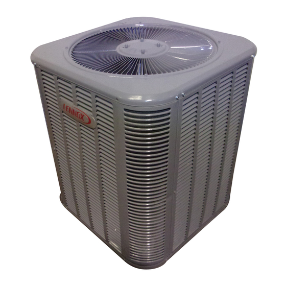
This 13ACX outdoor unit is designed for use with HFC-410A
refrigerant only. This unit must be installed with an approved
indoor unit. See the Lennox 13ACX Product Specifications
bulletin (EHB) for approved indoor component match ups.
These instructions are intended as a general guide and do
not supersede local codes in any way. Consult authorities
having jurisdiction before installation.
STEP 1 -- SETTING THE UNIT -- Clearances
CLEARANCE ON ALL SIDES — INCHES (MILLIMETERS)
6 (152)
12 (305)
36 (914)
MINIMUM CLEARANCE BETWEEN TWO UNITS
7/2012
*2P72012*
NOTES:
S
30 (762)
S
LINE SET
CONNECTIONS
24 (610)
INSTALLATION
INSTRUCTIONS
Merit
Series 13ACX Units
®
AIR CONDITIONER
506945-01
5/2013
Supersedes 7/2012
Improper installation, adjustment, alteration, service or
maintenance can cause personal injury, loss of life, or
damage to property.
Installation and service must be performed by a licensed
professional installer (or equivalent) or a service agency.
Before attempting to perform any service or maintenance,
turn the electrical power to unit OFF at disconnect switch.
As with any mechanical equipment, contact with sharp
sheet metal edges can result in personal injury. Take care
while handling this equipment.
Clearance to one of the other three
sides must be 36 inches (914mm).
Clearance to one of the remaining
two sides may be 12 inches
(305mm) and the final side may be
6 inches (152mm).
CONNECTIONS
FIGURE 1
Page 1
WARNING
CAUTION
CAUTION
MINIMUM CLEARANCE
ABOVE UNIT
48 (1219)
ACCESS
PANEL
LINE SET
506945-01
*P506945-01*
Litho U.S.A.
Advertisement
Table of Contents

Related Manuals for Lennox Merit 13ACX-018-230


Summary of Contents for Lennox Merit 13ACX-018-230
-
Page 1: Installation Instructions
This 13ACX outdoor unit is designed for use with HFC-410A refrigerant only. This unit must be installed with an approved CAUTION indoor unit. See the Lennox 13ACX Product Specifications bulletin (EHB) for approved indoor component match ups. As with any mechanical equipment, contact with sharp These instructions are intended as a general guide and do sheet metal edges can result in personal injury. -
Page 2: Step 1 -- Setting The Unit
This will diminish unit performance VIEW and longevity. FIGURE 2 PLACEMENT TABLE 1 UNIT DIMENSIONS INSTALL UNIT AWAY Model Numbers FROM WINDOWS 13ACX-018-230 24-1/4 (616) 25-1/4 (641) 13ACX-024-230 24-1/4 (616) 25-1/4 (641) 13ACX-030-230 24-1/4 (616) 29-1/4 (743) 13ACX-036-230... -
Page 3: Installation
LINE SET IMPORTANT — Refrigerant lines must not contact structure. INSTALLATION REFRIGERANT LINE SET — INSTALLING Line Set Isolation — The following illustrations are VERTICAL RUNS (NEW CONSTRUCTION SHOWN) examples of proper refrigerant line set isolation: NOTE — Insulate liquid line when it is routed through areas where the surrounding ambient temperature could become higher than the REFRIGERANT LINE SET —... - Page 4 Polyol ester (POE) LIQUID LINE FILTER DRIER INSTALLATION oils are used in Lennox units charged with HFC-410A refrigerant. Residual mineral oil can act as an insula The filter drier (one is shipped with each 13ACX unit) must tor, preventing proper heat transfer.
- Page 5 STEP 2 -- REFRIGERANT PIPING -- Removing Existing Indoor Metering Device TYPICAL EXISTING FIXED ORIFICE TYPICAL EXISTING EXPANSION VALVE REMOVAL REMOVAL PROCEDURE PROCEDURE (UNCASED COIL SHOWN) (UNCASED COIL SHOWN) STUB END TWO-PIECE PATCH PLATE LIQUID LINE DISTRIBUTOR TUBES (UNCASED COIL ONLY) ORIFICE EXPANSION LIQUID LINE ORIFICE HOUSING...
-
Page 6: Cap And Core Removal
STEP 2 -- REFRIGERANT PIPING -- Brazing Procedures CAP AND CORE REMOVAL CUT AND DEBUR Cut ends of the refrigerant lines square (free from nicks or dents) Remove service cap and core from and debur the ends. The pipe must remain round. Do not crimp end both the suction / vapor and liquid line of the line. -
Page 7: Braze Line Set
WRAP SERVICE VALVES To help protect service valve seals during brazing, wrap water-saturated cloths around service valve bodies and copper tube stubs. Use additional water-saturated cloths underneath the valve body to protect the base paint. FLOW NITROGEN Flow regulated nitrogen (at 1 to 2 psig) through the refrigeration gauge set into the valve stem port connection on the liquid service valve and out of the suction / vapor valve stem port. - Page 8 STEP 2 -- REFRIGERANT PIPING -- Installing Indoor Expansion Valve This outdoor unit is designed for use in systems that use either an fixed orifice (RFC) (included with outdoor unit), or expansion valve metering device (purchased separately) at the indoor coil. See the 13ACX Product Specifications bulletin (EHB) for approved expansion valve kit match ups.
-
Page 9: Step 3 -- Leak Test And Evacuation
STEP 3 -- LEAK TEST AND EVACUATION LEAK TEST HIGH MANIFOLD GAUGE SET TO VAPOR SERVICE VALVE (ANGLE OR BALL TYPE) NITROGEN OUTDOOR UNIT HFC-410A CONNECT GAUGE SET Connect the high pressure hose of an HFC-410A manifold gauge set to the vapor valve service port. NOTE —... - Page 10 STEP 3 -- LEAK TEST AND EVACUATION (CONTINUED) EVACUATION HIGH CONNECT GAUGE SET NOTE — Remove cores from service valves (if not already done). Connect low side of manifold gauge set with 1/4 SAE in-line tee to vapor line service valve Connect high side of manifold gauge set to liquid line service valve MANIFOLD...
-
Page 11: Install Thermostat
STEP 4 -- ELECTRICAL -- Circuit Sizing and Wire Routing In the U.S.A., wiring must conform with current local codes and IMPORTANT ! the current National Electric Code (NEC). In Canada, wiring must conform with current local codes and the current If unit is equipped with a crankcase heater, it should Canadian Electrical Code (CEC). -
Page 12: Step 5 -- Unit Start-Up
STEP 4 -- ELECTRICAL (CONTINUED) -- High Voltage and Field Control Wiring The following illustration provide an example of control wiring connections when using standard thermostat. ROUTING HIGH VOLTAGE, GROUND AND CONTROL WIRING FIELD CONTROL WIRING HIGH VOLTAGE / GROUND WIRES THERMOSTAT INDOOR UNIT Any excess high voltage field wiring should be... - Page 13 TABLE 3. TORQUE REQUIREMENTS gauge set that features low loss anti-blow back fittings. Parts Recommended Torque Manifold gauge set used with HFC-410A refrigerant systems must be capable of handling the higher system Service valve cap 8 ft.- lb. 11 NM operating pressures.
- Page 14 Before attempting to perform any service or mainte 1. Ask your Lennox dealer to show you where your indoor nance, turn the electrical power to unit OFF at discon unit's filter is located. It will be either at the indoor unit nect switch.
-
Page 15: Start Up Checks
13ACX Start-Up and Performance Checklist Customer Address Indoor Unit Model Serial Outdoor Unit Model Serial Notes: START UP CHECKS Refrigerant Type: Rated Load Amps: Actual Amps Rated Volts Actual Volts Condenser Fan Full Load Amps Actual Amps: COOLING MODE Suction Pressure: Liquid Pressure: Supply Air Temperature: Ambient Temperature:...