Advertisement
Quick Links
Service Literature
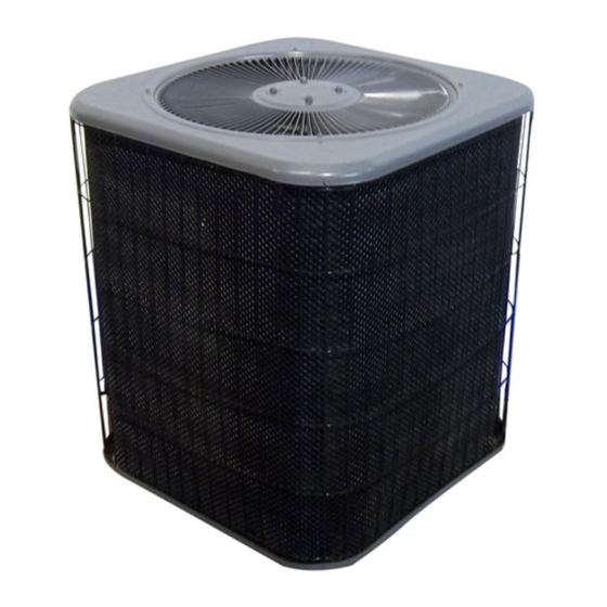
The 13ACD is a residential split-system condensing unit
with SEER ratings up to 14.80. The series is designed for
use with expansion valves (TXV) or refrigerant flow control
(RFC). All 13ACD units utilize scroll compressors.
13ACD condensing units are available in 1−1/2, 2, 2 -1/2, 3, 3
-1/2, 4 and 5 ton capacities. All major components (indoor
blower and coil) must be matched according to Lennox rec-
ommendations for the compressor to be covered under war-
ranty. Refer to the Engineering Handbook for approved sys-
tem matchups.
Information contained in this manual is intended for use by
qualified service technicians only. All specifications are subject
to change.
This manual is divided into sections which discuss the
major components, refrigerant system, charging proce-
dure, maintenance and operation sequence.
WARNING
Improper installation, adjustment, alteration, service
or maintenance can cause property damage, person-
al injury or loss of life. Installation and service must
be performed by a qualified installer or service
agency.
WARNING
Refrigerant can be harmful if it is inhaled. Refrigerant
must be used and recovered responsibly.
Failure to follow this warning may result in personal
injury or death.
TABLE OF CONTENTS
Specifications / Electrical Data
I Unit Components
. . . . . . . . . . . . . . . . . . .
II Refrigerant System
. . . . . . . . . . . . . . . . .
III Charging
. . . . . . . . . . . . . . . . . . . . . . . . .
IV Maintenance
. . . . . . . . . . . . . . . . . . . . . .
V Wiring and Operating Sequence
Corp. 0518−L8
Revised 03−2007
13ACD SERIES UNITS
. . . . . . . . .
Page 2
Page 3
Page 5
Page 6
Page 11
. . . . .
Page 12
Page 1
ELECTROSTATIC DISCHARGE (ESD)
Precautions and Procedures
CAUTION
Electrostatic discharge can affect electronic
components. Take precautions during unit instal-
lation and service to protect the unit's electronic
controls. Precautions will help to avoid control
exposure to electrostatic discharge by putting
the unit, the control and the technician at the
same electrostatic potential. Neutralize electro-
static charge by touching hand and all tools on an
unpainted unit surface before performing any
service procedure.
IMPORTANT
The Clean Air Act of 1990 bans the intentional venting
of (CFC's and HFC's) as of July 1, 1992. Approved
methods of recovery, recycling or reclaiming must be
followed. Fines and/or incarceration my be levied for
noncompliance.
13ACD
©2005 Lennox Industries Inc.
Advertisement

Related Manuals for Lennox 13ACD Series


Summary of Contents for Lennox 13ACD Series
- Page 1 13ACD condensing units are available in 1−1/2, 2, 2 -1/2, 3, 3 -1/2, 4 and 5 ton capacities. All major components (indoor blower and coil) must be matched according to Lennox rec- ommendations for the compressor to be covered under war- ranty.
- Page 2 SPECIFICATIONS General Model No. 13ACD−018 13ACD−024 13ACD−030 13ACD−036 13ACD−042 13ACD−048 13ACD−060 Data (−1, −2 units) Nominal Tonnage Connections Liquid line o.d. − in. (sweat) Suction line o.d. − in. 1-1/8 Refrigerant (R-22) furnished 4 lbs. 0 oz. 4 lbs. 8 oz. 5 lbs. 5 oz. 6 lbs. 15 oz. 6 lbs. 15 oz. 9 lbs. 8 oz. 13 lbs.
- Page 3 See figure 2. Single−pole contactors are used thermostat demand is satisfied, the time delay opens the in 13ACD series units. K1 is energized by the indoor ther- circuit to the compressor contactor coil and the compressor mostat terminal Y1 (24V) when thermostat demand is is de−energized.
- Page 4 NOTE − During operation, the head of a scroll compressor may ter of the scroll and is discharged. If the compressor is re- be hot since it is in constant contact with discharge gas. placed, conventional Lennox cleanup practices must be used. SUCTION SUCTION...
- Page 5 (sweat connections) to the indoor See compressor nameplate or ELECTRICAL DATA for evaporator coil (flare or sweat connections). Use Lennox compressor specifications. L15 (sweat) series line sets as shown in table 1. C − Condenser Fan Motor TABLE 1 All units use single−phase PSC fan motors which require a run...
- Page 6 Table 2 Service Valve Torque Requirements (Valve Closed) Part Recommended Torque stem cap service Service valve cap 8 ft.− lb. 11 NM port Sheet metal screws 16 in.− lb. 2 NM insert hex Machine screws #10 28 in.− lb. 3 NM to outdoor coil wrench here Compressor bolts...
- Page 7 Manual trace amount of HCFC-22. [A trace amount is a maxi- Corp.9351−L9 and available on the Lennox DaveNet mum of 2 ounces (57 g) or 3 pounds (31 kPa) pressure.] web site for line sets over 50 feet (15.2 m).
- Page 8 5 − Evacuate the line set and indoor unit to an absolute D − Charging pressure of 23,000 microns (29.01 inches of mercury). Units are factory-charged with the amount of HCFC−22 re- During the early stages of evacuation, it is desirable to frigerant indicated on the unit rating plate.
- Page 9 Charge Using Subcooling Method Charge using Subcooling Method Outdoor Temp. >65°F (18°C) Outdoor Temp. t65ºF (18ºC) (TXV Systems) If you charge a fixed orifice system when the outdoor ambi- This charging procedure should not be used if ambient tem- ent is 65_F (18_C) or above, use the subcooling method to peratures are below 65ºF.
- Page 10 Checking Charge Using Normal Operating Pressures IMPORTANT Use table 8 to help perform maintenance checks. Table 8 is not a procedure for charging the system. Mi- nor variations in these pressures may be due to differ- ences in installations. Significant deviations could mean that the system is not properly charged or that a problem exists with some component in the system.
- Page 11 IV − MAINTENANCE Then, using pliers to grip the head of the push pins, pull straight out to extract the push pins along one side of the coil. If necessary, remove the push pins along the WARNING back of the unit; it is usually unnecessary to fully re- move the inner mesh screen.
- Page 12 V − WIRING DIAGRAMS AND SEQUENCE OF OPERATION 13ACD NOTE− The thermostat used may be electromechanical or electronic. NOTE− Transformer in indoor unit supplies power (24 VAC) to the thermostat and outdoor unit controls. COOLING: 1− Cooling demand initiates at Y1 in the thermostat. 2−...