
Related Manuals for Gigabyte GA-Z77X-UD3H


Summary of Contents for Gigabyte GA-Z77X-UD3H
- Page 1 Инструкция для GigaByte GA-Z77X-UD3H rev. 1.0 Перейти в карточку товара 8 800 775 98 98...
- Page 2 GA-Z77X-UD3H User's Manual Rev. 1002 12ME-Z77XU3H-1002R...
- Page 3 Motherboard GA-Z77X-UD3H Motherboard GA-Z77X-UD3H Mar. 16, 2012 Mar. 16, 2012...
-
Page 4: Identifying Motherboard Revision
Copyright © 2012 GIGA-BYTE TECHNOLOGY CO., LTD. All rights reserved. The trademarks mentioned in this manual are legally registered to their respective owners. Disclaimer Information in this manual is protected by copyright laws and is the property of GIGABYTE. without prior notice. No part of this manual may be reproduced, copied, translated, transmit- ted, orpublished in any form or by any means without GIGABYTE's prior written permission. -
Page 5: Table Of Contents
Table of Contents Box Contents ........................6 Optional Items .........................6 GA-Z77X-UD3H Motherboard Layout ................7 GA-Z77X-UD3H Motherboard Block Diagram ..............8 Chapter 1 Hardware Installation ..................9 Installation Precautions ................... 9 ................... 10 Installing the CPU and CPU Cooler............... 13 1-3-1 Installing the CPU ....................13 1-3-2 Installing the CPU Cooler ..................15... - Page 6 Download Center ................... 62 New Program ....................62 Chapter 4 Unique Features ...................63 Xpress Recovery2 ..................63 BIOS Update Utilities ..................66 4-2-1 Updating the BIOS with the Q-Flash Utility ............66 4-2-2 Updating the BIOS with the @BIOS Utility ............69 EasyTune 6 ....................
-
Page 7: Box Contents
One GC-WB150D (including two antennas, one USB 2.0 cable, driver disk, and user's manual) Only for GA-Z77X-UD3H The box contents above are for reference only and the actual items shall depend on the product package you obtain. The box contents are subject to change without notice. -
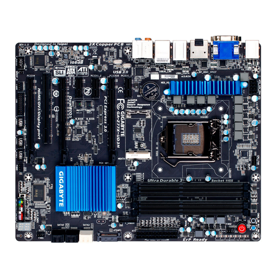
Page 8: Ga-Z77X-Ud3H Motherboard Layout
GA-Z77X-UD3H Motherboard Layout CMOS_SW CPU_FAN RST_SW KB_USB3 VCORE ATX_12V_2X4 CPUVTT LGA1155 CPUPLL DVI VGA VDIMM DDRVTT PCHIO DP_HDMI_SPDIF USB3_ESATA USB30_LAN VL800 AUDIO mSATA PCIEX1_1 GA-Z77X-UD3H Atheros GbE LAN PCIEX16 F_USB30 PCIEX1_2 B_BIOS BBIOS_LED Intel ® Marvell PCIEX1_3 SATA3 MBIOS_LED 88SE9172... -
Page 9: Ga-Z77X-Ud3H Motherboard Block Diagram
GA-Z77X-UD3H Motherboard Block Diagram PCIe CLK CPU CLK+/- (100 MHz) (100 MHz) DDR3 1600/1333/1066 MHz LGA1155 Dual Channel Memory 2 PCI Express x8 1 PCI Express x16 4 USB 3.0/2.0 2 SATA 6Gb/s Switch Marvell VL800 88SE9172 PCI Express Bus... -
Page 10: Chapter 1 Hardware Installation
Chapter 1 Hardware Installation Installation Precautions The motherboard contains numerous delicate electronic circuits and components which can become damaged as a result of electrostatic discharge (ESD). Prior to installation, carefully read the user's manual and follow these procedures: Prior to installation, make sure the chassis is suitable for the motherboard. Prior to installation, do not remove or break motherboard S/N (Serial Number) sticker or warranty sticker provided by your dealer. - Page 11 Support for Intel ® Core ™ i7 processors/Intel ® Core ™ i5 processors/ Intel ® Core ™ i3 processors/Intel ® Pentium ® processors/Intel ® Celeron ® processors in the LGA1155 package (Go to GIGABYTE's website for the latest CPU support list.) L3 cache varies with CPU Chipset Intel...
- Page 12 Storage Interface Chipset: 2 x SATA 6Gb/s connectors (SATA3 0/SATA3 1) supporting up to 2 SATA 6Gb/s devices 4 x SATA 3Gb/s connectors (SATA2 2~5) supporting up to 4 SATA 3Gb/s devices 1 x mSATA connector * The SATA2 5 connector will become unavailable when the mSATA connector is installed with a solid state drive.
- Page 13 Back Panel 1 x PS/2 keyboard/mouse port 1 x D-Sub port Connectors 1 x DVI-D port 1 x optical S/PDIF Out connector 1 x HDMI port 1 x DisplayPort 2 x eSATA 6Gb/s connectors 6 x USB 3.0/2.0 ports 1 x RJ-45 port 6 x audio jacks (Center/Subwoofer Speaker Out, Rear Speaker Out, Side Speaker Out, Line In/Mic In, Line Out) I/O Controller...
-
Page 14: Installing The Cpu And Cpu Cooler
Installing the CPU and CPU Cooler Read the following guidelines before you begin to install the CPU: Make sure that the motherboard supports the CPU. (Go to GIGABYTE's website for the latest CPU support list.) Always turn off the computer and unplug the power cord from the power outlet before installing the CPU to prevent hardware damage. - Page 15 B. Follow the steps below to correctly install the CPU into the motherboard CPU socket. Before installing the CPU, make sure to turn off the computer and unplug the power cord from the power outlet to prevent damage to the CPU. Step 1: Step 2: Gently press the CPU socket lever handle down...
-
Page 16: Installing The Cpu Cooler
1-3-2 Installing the CPU Cooler Follow the steps below to correctly install the CPU cooler on the motherboard. (The following procedure uses Intel ® boxed cooler as the example cooler.) Male Push Pin Direction of the Arrow Sign The Top on the Male of Female Push Pin... -
Page 17: Installing The Memory
Installing the Memory Read the following guidelines before you begin to install the memory: Make sure that the motherboard supports the memory. It is recommended that memory of the same capacity, brand, speed, and chips be used. (Go to GIGABYTE's website for the latest supported memory speeds and memory modules.) Always turn off the computer and unplug the power cord from the power outlet before installing the memory to prevent hardware damage. -
Page 18: Installing A Memory
1-4-2 Installing a Memory Before installing a memory module, make sure to turn off the computer and unplug the power cord from the power outlet to prevent damage to the memory module. DDR3 and DDR2 DIMMs are not compatible to each other or DDR DIMMs. Be sure to install DDR3 DIMMs on this motherboard. Notch DDR3 DIMM your memory modules in the memory sockets. -
Page 19: Installing An Expansion Card
Installing an Expansion Card Read the following guidelines before you begin to install an expansion card: Make sure the motherboard supports the expansion card. Carefully read the manual that came with your expansion card. Always turn off the computer and unplug the power cord from the power outlet before installing an expansion card to prevent hardware damage. -
Page 20: Setting Up Amd Crossfirex
Setting up AMD CrossFireX ™ A. System Requirements Windows 7, XP operating system A CrossFireX/SLI-supported motherboard with two PCI Express x16 slots and correct driver Two CrossFireX/SLI-ready graphics cards of identical brand and chip and correct driver CrossFireX (Note) /SLI bridge connectors power requirement) B. -
Page 21: Back Panel Connectors
Back Panel Connectors PS/2 Keyboard/Mouse Port Use this port to connect a PS/2 mouse or keyboard. USB 3.0/2.0 Port D-Sub Port The D-Sub port supports a 15-pin D-Sub connector. Connect a monitor that supports D-Sub connection to this port. DVI-D Port (Note) (the actual resolutions supported depend on the monitor being used). - Page 22 DisplayPort DisplayPort is one of the new generation interface technologies that delivers high quality digital imaging and audio, supporting bi-directional audio transmition. DisplayPort can support both DPCP and HDCP content protection mechanisms. Connect the audio/video device that supports DisplayPort to this port. The DisplayPort Technology can support a maximum resolution of 2560x1600 but the actual resolutions supported depend on the monitor being used.
-
Page 23: Onboard Buttons, Switches, And Leds
Onboard Buttons, Switches, and LEDs BIOS Switch and BIOS LED Indicators The BIOS switch (SW4) allows users to easily select a different BIOS for boot up or overclocking, helping to reduce BIOS failure during overclocking. The LED indicator (MBIOS_LED/BBIOS_LED) shows which BIOS is active. BIOS Switch: 1: Main BIOS (Boot from the main BIOS) 3: Backup BIOS (Boot from the backup BIOS) - Page 24 Voltage Measurement Points Users can use a multimeter to measure component voltages, including VCORE, CPU VTT, VSA, CPU PLL, DDR VTT, VDIMM, and PCHIO. You can employ following way to measure component voltages. VCORE Pin 1 Pin No. CPUVTT +12V Pin 1 Pin 1 CPUPLL...
-
Page 25: Internal Connectors
Internal Connectors ATX_12V_2X4 F_PANEL ATX4P1 F_AUDIO CPU_FAN SPDIF_O SYS_FAN1/2/3/4 F_USB1/F_USB2/F_USB3 SATA3 0/1 F_USB30 SATA2 2/3/4/5 mSATA CLR_CMOS Read the following guidelines before connecting external devices: First make sure your devices are compliant with the connectors you wish to connect. Before installing the devices, be sure to turn off the devices and your computer. Unplug the power cord from the power outlet to prevent damage to the devices. - Page 26 1/2) ATX_12V_2X4/ATX (2x4 12V Power Connector and 2x12 Main Power Connector) With the use of the power connector, the power supply can supply enough stable power to all the components off and all devices are properly installed. The power connector possesses a foolproof design. Connect the power supply cable to the power connector in the correct orientation.
- Page 27 3) ATX4P1 (PCIe Power Connector) The power connector provide auxiliary power to the onboard PCI Express x16 slots. When two or more graphics cards are installed, we recommend that you connect the SATA power cable(s) from the power supply to the ATX4P1 connector to ensure system stability. Pin No.
- Page 28 6) SATA3 0/1 (SATA 6Gb/s Connectors, Controlled by Intel Z77 Chipset) The SATA connectors conform to SATA 6Gb/s standard and are compatible with SATA 3Gb/s and SATA 1.5Gb/s standard. Each SATA connector supports a single SATA device. The "SATA3 0" and "SATA3 1" connectors support RAID 0 and RAID 1.
- Page 29 8) mSATA (Solid-State Drive Connector, Controlled by the Intel Z77 Chipset) The mSATA connector conforms to SATA 3Gb/s standard and can connect to a single solid-state drive. When the mSATA connector is installed with a solid-state drive, the SATA2 5 connector will become unavailable.
- Page 30 10) F_PANEL (Front Panel Header) Connect the power switch, reset switch, speaker, chassis intrusion switch/sensor and system status indicator on the chassis to this header according to the pin assignments below. Note the positive and negative pins before connecting the cables. Message/Power/ Sleep LED Power Switch...
- Page 31 11) F_AUDIO (Front Panel Audio Header) your chassis front panel audio module to this header. Make sure the wire assignments of the module connector match the pin assignments of the motherboard header. Incorrect connection between the module connector and the motherboard header will make the device unable to work or even damage it. For HD Front Panel Audio: For AC'97 Front Panel Audio: Pin No.
- Page 32 13) F_USB1/F_USB2/F_USB3 (USB 2.0/1.1 Headers) optional USB bracket. For purchasing the optional USB bracket, please contact the local dealer. Pin No. Power (5V) Power (5V) USB DX- USB DY- USB DX+ USB DY+ No Pin 14) F_USB30 (USB 3.0/2.0 Header) optional 3.5"...
- Page 33 15) TPM (Trusted Platform Module Header) You may connect a TPM (Trusted Platform Module) to this header. Pin No. Pin No. LCLK LAD0 LFRAME No Pin LRESET SB3V SERIRQ LAD3 LAD2 VCC3 LAD1 SUSCLK 16) CLR_CMOS (Clear CMOS Jumper) CMOS values to factory defaults. To clear the CMOS values, use a metal object like a screwdriver to touch the two pins for a few seconds.
-
Page 34: Chapter 2 Bios Setup
Chapter 2 BIOS Setup BIOS (Basic Input and Output System) records hardware parameters of the system in the CMOS on the motherboard. Its major functions include conducting the Power-On Self-Test (POST) during system startup, saving system parameters and loading operating system, etc. BIOS includes a BIOS Setup program that allows When the power is turned off, the battery on the motherboard supplies the necessary power to the CMOS to To access the BIOS Setup program, press the <Delete>... -
Page 35: Startup Screen
Startup Screen The following startup Logo screen will appear when the computer boots. Function Keys Function Keys: <DEL>: BIOS SETUP\Q-FLASH Press the <Delete> key to enter BIOS Setup or to access the Q-Flash utility in BIOS Setup. <F9>: SYSTEM INFORMATION Press the <F9>... -
Page 36: The Main Menu
The Main Menu A. The 3D BIOS Screen (Default) On GIGABYTE's uniquely designed 3D BIOS screen, you can use your mouse to move through the motherboard arrow over the CPU and memory sockets and enter the System Tuning function menu icons at the bottom of the screen or press <F1> to switch to the main menu of the BIOS Setup program. - Page 37 BIOS Setup Program Function Keys < >< > Move the selection bar to select a setup menu < >< > <Enter> Execute command or enter a menu <+>/<Page Up> Increase the numeric value or make changes <->/<Page Down> Decrease the numeric value or make changes <F1>...
-
Page 38: M.i.t
M.I.T. Whether the system will work stably with the overclock/overvoltage settings you made is dependent to CPU, chipset, or memory and reduce the useful life of these components. This page is for advanced users only and we recommend you not to alter the default settings to prevent system instability or other unexpected results. - Page 39 M.I.T. Current Status This screen provides information on CPU/memory frequencies/parameters. Advanced Frequency Settings CPU/PCIe Base Clock Allows you to manually set the CPU base clock and PCIe bus frequency in 0.01 MHz increments. (Default: Auto) Important: It is highly recommended that the CPU frequency be set in accordance with the CPU Internal Graphics Clock Allows you to set the onboard graphics clock.
- Page 40 Advanced CPU Core Features CPU Clock Ratio, CPU Frequency The settings under the two items above are synchronous to those under the same items on the Advanced Frequency Settings menu. Intel(R) Turbo Boost Technology (Note) Allows you to determine whether to enable the Intel CPU Turbo Boost technology. Auto lets the BIOS Turbo Ratio (1-Core Active~4-Core Active) (Note) Allows you to set the CPU Turbo ratios for different number of active cores.
- Page 41 CPU Enhanced Halt (C1E) (Note 1) Enables or disables Intel CPU Enhanced Halt (C1E) function, a CPU power-saving function in system halt state. When enabled, the CPU core frequency and voltage will be reduced during system halt state to decrease power consumption. Auto C3/C6 State Support (Note 1) Allows you to determine whether to let the CPU enter C3/C6 mode in system halt state.
- Page 42 Advanced Memory Settings (Note) , System Memory Multiplier (SPD), Memory Frequency(Mhz) The settings under the three items above are synchronous to those under the same items on the Advanced Frequency Settings menu. Performance Enhance Allows the system to operate at three different performance levels. Normal Lets the system operate at its basic performance level.
- Page 43 Channel A/B Timing Settings This sub-menu provides memory timing settings for each channel of memory. The respective timing setting DRAM Timing Selectable is set to Quick or Expert. Note: Your system may become unstable or fail to boot after you make changes on the memory timings. If this occurs, please reset the board to default values by loading optimized defaults or clearing the CMOS values.
- Page 44 3D Power Control PWM Phase Control Allows you to automatically change the PWM phase according to the CPU load. The power-saving levels are (from lowest to highest): eXm Perf (Extreme Performance ), High Perf (High Performance), Perf (Performance), Balanced, Mid PWR (Mid Power), and Lite PWR (Light Power). Auto lets the BIOS Vcore Voltage Response Standard~Fast Selects Standard or Fast which represents different levels of the response time...
- Page 45 Vcore Loadline Calibration ( Allows you to set the Load-Line Calibration level for the Vcore. The levels are (from highest to lowest): Extreme, Turbo, High, Medium, Low, and Standard. Selecting a higher level keeps the Vcore more consistent with what is set in BIOS under heavy load. Auto GFX Voltage Loadline Calibration Allows you to set the Load-Line Calibration level for the GFX voltage.
- Page 46 GFX Current Protection Allows you to set the over-current protection level for the GFX voltage. Standard~Extreme Selects Standard, Low, Medium, High, Turbo, or Extreme which represents different level of over-current protection for the GFX voltage. DDR CH(A/B) Current Protection Allows you to set the over-current protection level for the memory voltage. Standard~Extreme Selects Standard, Low, Medium, High, Turbo, or Extreme which represents different level of over-current protection for the memory voltage.
- Page 47 PC Health Status Reset Case Open Status Disabled Keeps or clears the record of previous chassis intrusion status. (Default) Enabled Clears the record of previous chassis intrusion status and the Case Open "No" at next boot. Case Open Displays the detection status of the chassis intrusion detection device attached to the motherboard CI clear the chassis intrusion status record, set Reset Case Open Status to Enabled, save the settings to the CMOS, and then restart your system.
- Page 48 CPU Vcore/Dram Voltage/+3.3V/+12V Displays the current system voltages. CPU/PCH/System Temperature Displays current CPU/Chipset/System temperature. CPU/System FAN Speed Displays current CPU/system fan speeds. CPU Warning Temperature Sets the warning threshold for CPU temperature. When CPU temperature exceeds the threshold, BIOS will emit warning sound.
-
Page 49: System
System This section provides information on your CPU, memory, motherboard model, and BIOS version. You can also select the default language used by the BIOS and manually set the system time. System Language Selects the default language used by the BIOS. System Date Sets the system date. -
Page 50: Bios Features
BIOS Features Boot Option Priorities (Boot Option #1) and DVD ROM drive as the second priority (Boot Option #2). The list only Hard Drive BBS Priorities submenu will be presented here. string. Or if you want to install an operating system that supports GPT partitioning such as Windows 7 64-bit, select Hard Drive/CD/DVD ROM Drive/Floppy Drive/Network Device BBS Priorities and devices that support Boot from LAN function, etc. -
Page 51: Administrator Password
Limit CPUID Maximum (Note) Allows you to determine whether to limit CPUID maximum value. Set this item to Disabled for Windows XP operating system; set this item to Enabled for legacy operating system such as Windows NT4.0. (Default: Disabled) Execute Disable Bit (Note) Enables or disables Intel Execute Disable Bit function. -
Page 52: Peripherals
Peripherals LAN PXE Boot Option ROM Allows you to decide whether to activate the boot ROM integrated with the onboard LAN chip. (Default: Disabled) SATA Controller(s) (Intel Z77 Chipset) Enables or disables the integrated SATA controllers. (Default: Enabled) - 51 - BIOS Setup... - Page 53 SATA Mode Selection (Intel Z77 Chipset) SATA controllers to AHCI mode. RAID Enables RAID for the SATA controller. Serial ATA features such as Native Command Queuing and hot plug. (Default) xHCI Pre-Boot Driver (Intel Z77 Chipset) Enabled The USB 3.0 ports are routed to the xHCI controller before booting to OS. (Default) Disabled The USB 3.0 ports are routed to the EHCI controller before booting to OS.
- Page 54 Audio Controller Enables or disables the onboard audio function. (Default: Enabled) If you wish to install a 3rd party add-in audio card instead of using the onboard audio, set this item to Disabled. Init Display First Specifes the frst initiation of the monitor display from the installed PCI graphics card, PCI Express graphics card, or the onboard graphics.
- Page 55 OnBoard LAN Controller#1 Enables or disables the onboard LAN function. (Default: Enabled) If you wish to install a 3rd party add-in network card instead of using the onboard LAN, set this item to Disabled. installed. All PCI Express x1 slots will become unavailable when a PCIe x4 expansion card is installed.
- Page 56 GSATA Controller (Marvell 88SE9172 Chip, GSATA3 6 and GSATA3 7 connectors) the SATA controllers to AHCI mode. The area below displays the current status of the two SATA ports. mode. Serial ATA features such as Native Command Queuing and hot plug. (Default) RAID Mode Enables RAID for the SATA controllers.
-
Page 57: Power Management
Power Management AC BACK Determines the state of the system after the return of power from an AC power loss. Always Off The system stays off upon the return of the AC power. (Default) Always On The system is turned on upon the return of the AC power. Memory The system returns to its last known awake state upon the return of the AC power. - Page 58 High Precision Event Timer (Note) Enables or disables High Precision Event Timer (HPET) for Windows 7 operating system. (Default: Enabled) Soft-Off by PWR-BTTN Instant-Off Press the power button and then the system will be turned off instantly. (Default) Delay 4 Sec Press and hold the power button for 4 seconds to turn off the system.
-
Page 59: Save & Exit
Save & Exit Save & Exit Setup Press <Enter> on this item and select Yes. This saves the changes to the CMOS and exits the BIOS Setup program. Select No or press <Esc> to return to the BIOS Setup Main Menu. Exit Without Saving Press <Enter>... -
Page 60: Chapter 3 Drivers Installation
Chapter 3 Drivers Installation After installing the operating system, insert the motherboard driver disk into your optical drive. The driver Autorun screen is automatically displayed which looks like that shown in the screen shot below. (If the driver Autorun screen does not appear automatically, go to My Computer, double-click the optical drive and execute the Run.exe program.) Installing Chipset Drivers After inserting the driver disk, "Xpress Install"... -
Page 61: Application Software
Application Software This page displays all the utilities and applications that GIGABYTE develops and some free software. You can click the Install button on the right of an item to install it. Technical Manuals This page provides the content descriptions for this driver disk. Drivers Installation - 60 -... -
Page 62: Contact
Contact the URL on this page to link to the GIGABYTE website. System This page provides the basic system information. - 61 - Drivers Installation... -
Page 63: Download Center
Download Center To update the BIOS, drivers, or applications, click the Download Center button to link to the GIGABYTE website. The latest version of the BIOS, drivers, or applications will be displayed. New Program This page provides a quick link to GIGABYTE's lately developed utilities for users to install. You can click the Install button on the right of an item to install it. -
Page 64: Chapter 4 Unique Features
Chapter 4 Unique Features Xpress Recovery2 Xpress Recovery2 is a utility that allows you to quickly compress and back up your system data and perform restoration of it. Supporting NTFS, FAT32, SATA hard drives and restore it. Before You Begin: for the operating system. - Page 65 Step 3: Step 4: When partitioning your hard drive, make sure to leave After the operating system is installed, click Start, unallocated space (10 GB or more is recommended; right-click the Computer and select Manage. Go to actual size requirements vary, depending on the Disk Management to check disk allocation.
- Page 66 D. Using the Restore Function in Xpress Recovery2 Select RESTORE to restore the backup to your hard drive in case the system breaks down. The RESTORE option will not be present if no backup is created before. E. Removing the Backup Step 1: Step 2: If you wish to remove the backup file, select...
-
Page 67: Bios Update Utilities
BIOS Update Utilities GIGABYTE motherboards provide two unique BIOS update tools, Q-Flash and @BIOS . GIGABYTE Q-Flash ™ ™ and @BIOS are easy-to-use and allow you to update the BIOS without the need to enter MS-DOS mode. Additionally, this motherboard features the DualBIOS design, which enhances protection for the safety and ™... - Page 68 B. Updating the BIOS In the main menu of Q-Flash, use the keyboard or mouse to select an item to execute. When updating the Step 1: Update BIOS From Drive. The Save BIOS to Drive an independent SATA controller, use the <End> key during the POST to access Q-Flash. Select Flash Disk.
- Page 69 Step 4: During the POST, press <Delete> to enter BIOS Setup. Select Load Optimized Defaults on the Save & Exit screen and press <Enter> to load BIOS defaults. System will re-detect all peripheral devices after a BIOS update, so we recommend that you reload BIOS defaults. Select Yes to load BIOS defaults Step 5: Select Save &...
-
Page 70: Updating The Bios With The @Bios Utility
4-2-2 Updating the BIOS with the @BIOS Utility A. Before You Begin In Windows, close all applications and TSR (Terminate and Stay Resident) programs. This helps prevent unexpected failures when performing a BIOS update. During the BIOS update process, ensure the Internet connection is stable and do NOT interrupt the Internet connection (for example, avoid a power loss or switching off the Internet). -
Page 71: Easytune 6
EasyTune 6 settings or do overclock/overvoltage in Windows environment. The user-friendly EasyTune 6 interface also includes tabbed pages for CPU and memory information, letting users read their system-related information without the need to install additional software. The EasyTune 6 Interface Tabs Information Function The CPU tab provides information on the installed CPU and motherboard. -
Page 72: Q-Share
Q-Share you are able to share your data with computers on the same network, making full use of Internet resources. Directions for using Q-Share After installing Q-Share from the motherboard driver disk, go to Start>All Programs>GIGABYTE>Q-Share.exe to launch the Q-Share tool. Find the Q-Share icon Figure 1. -
Page 73: Extreme Hard Drive (X.h.d)
eXtreme Hard Drive (X.H.D) With GIGABYTE eXtreme Hard Drive (X.H.D) (Note 1) ready system for RAID 0 when a new SATA drive is added. For a RAID 0 array that already exists, users also can use X.H.D to easily add a hard drive into the array to expand its capacity. -
Page 74: Auto Green
Auto Green Auto Green is an easy-to-use tool that provides users with simple options to enable system power savings via a Bluetooth cell phone. When the phone is out of the range of the computer's Bluetooth receiver, the system First, you have to set your Bluetooth cell phone as a portable key. On the Auto Green main menu, click and then click . -
Page 75: Intel Rapid Start Technology
Intel Rapid Start Technology A. System Requirements Windows 7 with SP1 An SSD with size larger than the total system memory Intel Rapid Start Technology enabled in BIOS Setup AHCI/RAID mode supported (please note if the SSD has been assigned as a member of a RAID array, it cannot be used to set up Intel Rapid Start store partition);... - Page 76 DISKPART>detail disk (Displays the properties of the selected disk and the volumes on that disk) DISKPART>select volume X store partition. Refer to the results from "detail disk" for exact volume number) DISKPART>set id=84 override (Change the partition type) (Figure 3) GPT format: Follow the commands for MBR format.
-
Page 77: Intel Smart Connect Technology
Intel Smart Connect Technology Intel Smart Connect Technology allows user's computer to automatically update programs designed to work (Note) with the Internet to obtain their data while your system is suspended (sleeping). The user can obtain the latest data when the computer is waked up. A. - Page 78 Step 3: As shown in the left screenshot below, right-click on OEM, select New > Multi-String Value, and type WhiteList. Double-click WhiteList and type the application name to be added in Edit Multi-String. For example, to add Microsoft Outlook, type outlook.exe; to add Microsoft Windows Live, type wlmail. exe.
-
Page 79: Intel Smart Response
Intel Smart Response A. System Requirements An Intel Chipset-based motherboard An Intel Core series processor RAID enabled for the Intel SATA controllers in BIOS Setup A conventional SATA disk and an SSD (Note 1) Windows 7 with SP1 (Note 2) All motherboard drivers correctly installed original data on the hard disk will be lost once you enable RAID mode. - Page 80 Step 4: After selecting the SSD you want to use, the size of the SSD allocated for the cache memory, the hard disk/ volume to accelerate, and the acceleration mode, click OK Response Technology. The "Enable Acceleration" Dialog Box: Select the SSD to be used if more than one SSD is installed.
- Page 81 Unique Features - 80 -...
-
Page 82: Chapter 5 Appendix
Chapter 5 Appendix RAID Levels RAID 0 RAID 1 RAID 5 RAID 10 Minimum Number of Hard Drives Array Capacity Number of hard Size of the smallest (Number of hard (Number of hard drives * Size of the drive drives -1) * Size of drives/2) * Size of the smallest drive the smallest drive... - Page 83 B. Configuring SATA controller mode in BIOS Setup Make sure to configure the SATA controller mode correctly in system BIOS Setup. Step 1: Turn on your computer and press <Delete> to enter BIOS Setup during the POST (Power-On Self-Test). To create RAID, set SATA Mode Selection under the Peripherals menu to RAID (Figure 1).
- Page 84 C. Configuring a RAID array in RAID BIOS Enter the RAID BIOS setup utility to configure a RAID array. Skip this step and proceed with the installation of Windows operating system for a non-RAID configuration. Step 1: After the POST memory test begins and before the operating system boot begins, look for a message which says "Press <Ctrl-I>...
- Page 85 Step 3: After entering the CREATE VOLUME MENU screen, enter a volume name with 1~16 letters (letters cannot be special characters) under the Name item and press <Enter>. Then, select a RAID level (Figure 4). RAID levels supported include RAID 0, RAID 1, RAID 10, and RAID 5 (the selections available depend on the number of the hard drives being installed).
- Page 86 Step 5: Enter the array capacity and press <Enter>. Finally press <Enter> on the Create Volume item to begin creating the RAID array. When prompted to confirm whether to create this volume, press <Y> to confirm or <N> to cancel (Figure 6). Intel(R) Rapid Storage Technology - Option ROM - 11.0.0.1339 Copyright(C) 2003-11 Intel Corporation.
- Page 87 Recovery Volume Options Intel Rapid Recover Technology provides data protection by allowing users to easily restore data and system operation using a designated recovery drive. With the Rapid Recovery Technology, which employs RAID 1 functionality, users can copy the data from the master drive to the recovery drive; if needed, the data on the recovery drive can be restored back to the master drive.
- Page 88 Step 3: Press <Enter> under the Select Disks item. In the SELECT DISKS box, press <Tab> on the hard drive you want to use for the master drive and press <Space> on the hard drive you want to use for the recovery drive. (Make sure the recovery drive has equal or larger capacity than the master drive.) Then press <Enter>...
- Page 89 Delete RAID Volume To delete a RAID array, select Delete RAID Volume in MAIN MENU and press <Enter>. In the DELETE VOLUME MENU section, use the up or down arrow key to select the array to be deleted and press <Delete>. When prompted to confirm your selection (Figure 12), press <Y>...
- Page 90 A. Installing SATA hard drive(s) in your computer Attach one end of the SATA signal cable to the rear of the SATA hard drive and the other end to available SATA port on the motherboard. The Marvell 88SE9172 SATA controllers control the onboard eSATA connectors. Then connect the power connector from your power supply to the hard drive.
- Page 91 Figure 2 Step 2: Save changes and exit BIOS Setup. C. Configuring a RAID array in RAID BIOS Enter the RAID BIOS setup utility to configure a RAID array. Skip this step and proceed to the installation of Windows operating system for a non-RAID configuration. After the POST memory test begins and before the operating system boot begins, look for a message which says "Press <Ctrl>+<M>...
- Page 92 On the main screen of the RAID setup utility (Figure 4), use the left or right arrow key to move through tabs. Marvell BIOS Setup (c) 2009 Marvell Technology Group Ltd. [ Adapter ] [ Devices ] [ RAID ] Adapter 0 Vendor ID Device ID: 1B4B:91A2...
- Page 93 Step 2: The next screen displays the two hard drives you installed. Press <Enter> or <Space> on the two hard drives respectively to add them into the RAID array. Selected hard drives are marked with an asterisk (Figure 6). Then press <Enter> on NEXT. Marvell BIOS Setup (c) 2009 Marvell Technology Group Ltd.
- Page 94 NEXT: After completing the settings above, move to NEXT and press <Enter> to begin creating the array. When prompted to confirm, press <Y> to confirm or <N> to cancel (Figure 8). Marvell BIOS Setup (c) 2009 Marvell Technology Group Ltd. [ Adapter] [ Devices] [ RAID ]...
- Page 95 Delete the RAID Array: To deleted the existing array, press <Enter> on the RAID tab and select Delete VD. When the Delete VD menu appears, press <Enter> on the array to select it and then press <Enter> on NEXT. When prompted, press <Y> to confirm (Figure 10).
-
Page 96: Installing The Sata Raid/Ahci Driver And Operating System
5-1-3 Installing the SATA RAID/AHCI Driver and Operating System With the correct BIOS settings, you are ready to install Windows 7/XP. A. Installing Windows 7 For the Intel Z77: As Windows 7 already include Intel SATA RAID/AHCI driver, you do not need to install separate RAID/AHCI driver during the Windows installation process. - Page 97 B. Installing Windows XP Before installing Windows XP, connect a USB floppy disk drive to your computer first because you need to install the SATA RAID/AHCI driver from a floppy disk that contains the driver during the OS installation. Without the driver, the hard drive(s) may not be recognized during the Windows setup process.
- Page 98 Refer to the following for installing the driver during the Windows setup process. Step 1: Restart your system to boot from the Windows XP setup disk and press <F6> as soon as you see the message "Press F6 if you need to install a 3rd party SCSI or RAID driver." A screen will then appear asking you to specify an additional SCSI adapter.
- Page 99 For the Marvell 88SE9172: Insert the floppy disk containing the SATA RAID/AHCI driver and press <Enter>. Select either the 32-bit or 64-bit items depending on whether you want to install the 32-bit or 64-bit version of Windows XP (Figure 4). Both of the Marvell shared library and Marvell 91xx SATA RAID Controller need to be installed.
- Page 100 C. Rebuilding an Array Rebuilding is the process of restoring data to a hard drive from other drives in the array. Rebuilding applies only to fault-tolerant arrays such as RAID 1, RAID 5 or RAID 10 arrays. The procedures below assume a new drive is added to replace a failed drive to rebuild a RAID 1 array.
- Page 101 Performing the Rebuild in the Operating System While in the operating system, make sure the chipset driver has been installed from the motherboard driver disk. Then launch the Intel Rapid Storage Technology utility from All Programs in the Start menu. Step 2: Select a new drive to rebuild the RAID and click Rebuild.
- Page 102 Restoring the Master Drive to a Previous State (for Recovery Volume only) When two hard drives are set to Recovery Volume in Update on Request mode, you can restore the master drive data to the last backup state when needed. For example, in case the master drive detects a virus, you can restore the recovery drive data to the master drive.
- Page 103 For the Marvell 88SE9172: Turn off your computer and replace the failed hard drive with a new one. Restart your computer. To enable an automatic rebuild in the operating system, you have to set the new hard drive as a Spare drive in the RAID setup utility first.
- Page 104 Step 3: Make sure you have installed the Marvell RAID driver and Marvell Storage Utility from the motherboard driver disk. While in the operating system, launch the Marvell Storage Utility from Start\All Programs\Marvell Storage Utility\Marvell Tray, right-click on the icon in the notification area, and select Open MSU. Then login the Marvell Storage Utility.
- Page 105 The motherboard provides five audio jacks on the back panel which support 2/4/5.1/7.1-channel audio. (Note) The picture to the right shows the default audio jack Center/Subwoofer Line In Speaker Out assignments. Rear Speaker Out Front Speaker Out The integrated HD (High Definition) audio provides jack Side Mic In retasking capability that allows the user to change the...
- Page 106 Step 2: Connect an audio device to an audio jack. The Please select a function dialog box appears. Select the device according to the type of device you connect. Then click OK. Step 3: Go to the Speaker screen. On the Speaker Setting and Test tab, select 2, 4, 6, or 8-channel speaker according to the type of speaker configuration you wish to set up.
- Page 107 The S/PDIF Out jack can transmit audio signals to an external decoder for decoding to get the best audio quality. 1. Connecting a S/PDIF Out Cable: Connect a S/PDIF optical cable to the corresponding S/PDIF out connector as shown below and an external decoder for transmitting the S/PDIF digital audio signals.
- Page 108 Step 1: After installing the audio driver, the VIA HD Audio Deck icon will appear in the notification area. Click the icon to access the VIA HD Audio Deck. Step 2: Connect your microphone to the Mic in jack (pink) on the back panel or the Mic in jack (pink) on the front panel.
- Page 109 Step 5: After completing the settings above, click Start, point to All Programs, point to Accessories, and then click Sound Recorder to begin the sound recording. * Enabling Stereo Mix If the VIA HD Audio Deck does not display the recording device you wish to use, refer to the steps below. The following steps explain how to enable Stereo Mix (which may be needed when you want to record sound from your computer).
-
Page 110: Using The Sound Recorder
Step 4: Now you can access the VIA HD Audio Deck to configure Stereo Mix and use Sound Recorder to record the sound. 5-2-4 Using the Sound Recorder A. Recording Sound Make sure you have connected the sound input device (e.g. microphone) to the computer. To record the audio, click the Start Recording button To stop recording audio, click the... -
Page 111: Troubleshooting
Troubleshooting 5-3-1 Frequently Asked Questions To read more FAQs for your motherboard, please go to the Support & Downloads\FAQ page on GIGABYTE's website. Q: Why is the light of my keyboard/optical mouse still on after the computer shuts down? A: Some motherboards provide a small amount of standby power after the computer shuts down and that's why the light is still Q: How do I clear the CMOS values? A: For motherboards that have a Clear CMOS button, press this button to clear the CMOS values (before doing this, please turn off the computer and unplug the power cord). -
Page 112: Troubleshooting Procedure
5-3-2 Troubleshooting Procedure If you encounter any troubles during system startup, follow the troubleshooting procedure below to solve the problem. START Turn off the power. Remove all peripherals, connecting cables, and power cord etc. Make sure the motherboard does not short-circuit with the chassis or Isolate the short circuit. - Page 113 The power supply, CPU or When the computer is turned on, is the CPU cooler running? CPU socket might fail. The graphics card, expansion slot, or monitor Check if there is display on your monitor. might fail. Turn off the computer. Plug in the keyboard and mouse and restart the computer.
-
Page 114: Debug Led Codes
Debug LED Codes Regular Boot Code Description PEI Core is started. Pre-memory CPU initialization is started. 12~14 Reserved. Pre-memory North-Bridge initialization is started. 16~18 Reserved. Pre-memory South-Bridge initialization is started. 1A~2A Reserved. 2B~2F Memory initialization. Memory installed. 32~36 CPU PEI initialization. 37~3A IOH PEI initialization. - Page 115 Code Description PCI Bus initialization is started. PCI Bus hot plug initialization. PCI Bus enumeration for detecting how many resources are requested. Check PCI device requested resources. Assign PCI device resources. Console Output devices connect (ex. Monitor is lighted). Console input devices connect (ex. PS2/USB keyboard/mouse are activated). Super IO initialization.
-
Page 116: Recovery
Code Description USB device hot plug-in. PCI device hot plug. Clean-up of NVRAM. Reconfigure NVRAM settings. B8~BF Reserved. C0~CF Reserved. S3 Resume Code Description S3 Resume is stared (called from DXE IPL). Fill boot script data for S3 resume. Initializes VGA for S3 resume. OS S3 wake vector call. - Page 117 Code Description PCH initialization error. Some of the Architectural Protocols are not available. PCI resource allocation error. Out of Resources. No Space for Legacy Option ROM initialization. No Console Output Devices are found. No Console Input Devices are found. It is an invaild password. D9~DA Can't load Boot Option.
-
Page 118: Regulatory Statements
Regulatory Statements Regulatory Notices This document must not be copied without our written permission, and the contents there of must not be imparted to a third party nor be used for any unauthorized purpose. Contravention will be prosecuted. We believe that the information contained herein was accurate in all respects at the time of printing. - Page 119 Appendix - 118 -...
- Page 120 - 119 - Appendix...
- Page 121 Appendix - 120 -...
- Page 122 - 121 - Appendix...
- Page 123 Appendix - 122 -...
- Page 124 Shenyang Giga-Byte SINGAPORE PTE. LTD. - Singapore TEL: +86-24-83992901 WEB address : http://www.gigabyte.sg FAX: +86-24-83992909 Thailand GIGABYTE TECHNOLOGY (INDIA) LIMITED - India WEB address : http://th.giga-byte.com WEB address : http://www.gigabyte.in Vietnam Saudi Arabia WEB address : http://www.gigabyte.vn WEB address : http://www.gigabyte.com.sa Gigabyte Technology Pty.
- Page 125 WEB address : http://www.giga-byte.co.uk WEB address : http://www.gigabyte.com.tr Giga-Byte Technology B.V. - The Netherlands Russia WEB address : http://www.giga-byte.nl WEB address : http://www.gigabyte.ru GIGABYTE TECHNOLOGY FRANCE - France Poland WEB address : http://www.gigabyte.fr WEB address : http://www.gigabyte.pl Sweden Ukraine WEB address : http://www.gigabyte.se WEB address : http://www.gigabyte.ua...
- Page 126 GigaByte GA-Z77X-UD3H rev. 1.0 Описание Характеристики Отзывы...