Advertisement
Table of Contents
- 1 Table of Contents
- 2 Warning Decal Placement
- 3 Important Precautions
- 4 Before You Begin
- 5 Assembly
- 6 Operation and Adjustment
- 7 How to Fold and Move the Treadmill
- 8 Troubleshooting
- 9 Exercise Guidelines
- 10 Part List
- 11 Exploded Drawing
- 12 Ordering Replacement Parts
- 13 Recycling Information
- Download this manual
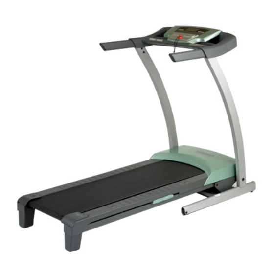
Model No. WETL40708.0
Serial No.
Write the serial number in the
space above for reference.
Serial
Number
Decal
QUESTIONS?
As a manufacturer, we are commit-
ted to providing complete customer
satisfaction. If you have questions,
or if there are missing parts,
please contact us at the numbers
or addresses listed below:
Call: 08457 089 009
Outside UK: 0 (44) 113 3877133
Fax: 0 (44) 113 3877125
E-mail: csuk@iconeurope.com
Write:
ICON Health & Fitness, Ltd.
Unit 4
Revie Road Industrial Estate
Revie Road, Beeston
Leeds, LS11 8JG,
UK
CAUTION
Read all precautions and instruc-
tions in this manual before using
this equipment. Save this manual
for future reference.
USER'S MANUAL
Advertisement
Table of Contents

Related Manuals for Weslo compact XL


Summary of Contents for Weslo compact XL
- Page 1 Model No. WETL40708.0 USER'S MANUAL Serial No. Write the serial number in the space above for reference. Serial Number Decal QUESTIONS? As a manufacturer, we are commit- ted to providing complete customer satisfaction. If you have questions, or if there are missing parts, please contact us at the numbers or addresses listed below: Call: 08457 089 009...
-
Page 2: Table Of Contents
Apply the decal in the location shown. Note: The decals may not be shown at actual size. WESLO is a registered trademark of ICON IP, Inc. -
Page 3: Important Precautions
IMPORTANT PRECAUTIONS WARNING: To reduce the risk of serious injury, read all important precautions and in- structions in this manual and all warnings on your treadmill before using your treadmill. ICON as- sumes no responsibility for personal injury or property damage sustained by or through the use of this product. - Page 4 20. Do not attempt to raise, lower, or move the 24. Never drop or insert any object into any treadmill until it is properly assembled. (See opening on the treadmill. DANGER: ASSEMBLY on page 6, and HOW TO FOLD AND MOVE THE TREADMILL on page 20.) Always unplug the power You must be able to safely lift 45 lbs.
-
Page 5: Before You Begin
And when youʼre not exercising, The model number and the location of the serial num- the unique COMPACT XL treadmill can be folded up, re- ber decal are shown on the front cover of this manual. quiring less than half the floor space of other treadmills. -
Page 6: Assembly
ASSEMBLY Assembly requires two persons. Set the treadmill in a cleared area and remove all packing materials; do not dispose of the packing materials until assembly is completed. Note: The underside of the treadmill walking belt is coated with high-performance lubricant. During shipping, a small amount of lubricant may be transferred to the top of the walking belt or the shipping carton. - Page 7 1. Make sure that the power cord is unplugged. Orient the Base (101) as shown. Attach four Base Feet (100) to the Base (101) in the locations shown with four M4.2 x 19mm Foot Screws (14). 2. Identify the Right Upright (98), which has a square hole in the location shown.
- Page 8 3. Orient the Left Upright (96) and the Base (101) as shown. Attach the Left Upright to the Base with two M10 x 53mm Patch Bolts (18), two M10 Flat Washers (16), and two M10 Star Washers (8); do not fully tighten the Patch Bolts yet. 4.
- Page 9 5. See the left inset drawing. Identify the two Upright Spacers (99). Open the included packet of grease, and apply grease to both sides of both Upright Spacers. Next, identify the outer side of each Upright Spacer. Have a second person raise the Frame (67) and hold it until step 7 is completed.
- Page 10 7. Identify the Right Handrail Cover (95) and the Left Handrail Cover (93). Slide the end of the Hole Right Handrail (94) through the hole in the Right Handrail Cover, and slide the end of Left Handrail (92) through the hole in the Left Handrail Cover.
- Page 11 9. Attach the Right Handrail (94) to the Console (109) with an M5 x 16mm Screw (13), an M5 Star Washer (12), and two M4.2 x 19mm Screws (10). Make sure that no wires are pinched. Start all three Screws before tight- ening any of them.
- Page 12 11. Attach the Console (109) to the Uprights (96, 98) with six M8 x 16mm Bolts (17) and six 5/16" Star Washers (2). Start all six Bolts before tightening them. 12. With the help of a second person, lower the Side View Uprights (96, 98) as shown.
- Page 13 13. Attach the ground wire on the Upright Wire (97) to the indicated hole in the Base (101) with a #8 Hole x 3/4" Ground Screw (11). Press the Grommet (90) into the Right Upright (98). Ground Wire 14. With the help of a second person, raise the Right Upright (98) and the Left Upright (not shown).
- Page 14 15. Attach the Rear Feet (70, 71) to the Frame (67) with four #8 x 1" Screws (7). Lower the Frame (67) (see HOW TO LOWER THE TREADMILL FOR USE on page 21). 16. Make sure that all parts are properly tightened before you use the treadmill. Note: Extra hardware may be included.
-
Page 15: Operation And Adjustment
OPERATION AND ADJUSTMENT THE PRE-LUBRICATED WALKING BELT Your treadmill features a walking belt coated with high-performance lubricant. IMPORTANT: Never apply sili- cone spray or other substances to the walking belt or the walking platform. Such substances will deterio- rate the walking belt and cause excessive wear. HOW TO PLUG IN THE POWER CORD Socket on Treadmill This product must be earthed. - Page 16 CONSOLE DIAGRAM Clip FEATURES OF THE CONSOLE To turn on the power, see page 17. To use the man- ual mode, see page 17. To use a preset workout, see The treadmill console offers a selection of features page 19. designed to make your workouts more effective.
- Page 17 HOW TO TURN ON THE POWER the Workout Select button repeatedly until only zeros appear in the display. IMPORTANT: If the treadmill has been exposed to cold temperatures, allow it to warm to room tem- 3. Start the walking belt. perature before turning on the power.
- Page 18 • Incline—This mode displays the incline of the into the console, and then release the Stop button. treadmill whenever the incline changes. An “M” for metric kilometers or an “E” for English miles will appear in the display. Press the Speed in- •...
- Page 19 HOW TO USE A PRESET WORKOUT speed or incline of the walking belt will automati- cally adjust to the speed or incline setting for the 1. Insert the key into the console. next segment. See HOW TO TURN ON THE POWER on page 17. The workout will continue in this way until the last segment of the workout ends.
-
Page 20: How To Fold And Move The Treadmill
HOW TO FOLD AND MOVE THE TREADMILL HOW TO FOLD THE TREADMILL FOR STORAGE Before folding the treadmill, adjust the incline to the lowest position. If you do not do this, you may damage the treadmill when you fold it. Remove the key and unplug the power cord. - Page 21 HOW TO LOWER THE TREADMILL FOR USE 1. Hold the upper end of the treadmill with your right hand. Pull the latch knob to the left and hold it. It may be neces- sary to push the frame forward as you pull the knob to the left.
-
Page 22: Troubleshooting
TROUBLESHOOTING Most treadmill problems can be solved by following the steps below. Find the symptom that applies, and follow the steps listed. If further assistance is needed, please see the front cover of this manual. PROBLEM: The power does not turn on SOLUTION: a. - Page 23 Locate the Reed Switch (55) and the Magnet (49) on the left side of the Pulley (58). Turn the Pulley 1/8 in. until the Magnet is aligned with the Reed Switch. Make sure that the gap between the Magnet and the Reed Switch is about 1/8 in.
- Page 24 PROBLEM: The walking belt is off-center or slips when walked on SOLUTION: a. If the walking belt is off-center, first remove the key and UNPLUG THE POWER CORD. If the walking belt has shifted to the left, use the hex key to turn the left idler roller bolt clockwise 1/2 of a turn;...
-
Page 25: Exercise Guidelines
EXERCISE GUIDELINES WARNING: Burning Fat—To burn fat effectively, you must exer- cise at a low intensity level for a sustained period of Before beginning this time. During the first few minutes of exercise, your or any exercise program, consult your physi- body uses carbohydrate calories for energy. -
Page 26: Part List
PART LIST—Model No. WETL40708.0 R0808A To locate the parts listed below, see the EXPLODED DRAWING near the end of this manual. Key No. Qty. Description Key No. Qty. Description 3/8" x 2" Bolt Rear Cushion 5/16" Star Washer Left Platform Cushion 3/8"... - Page 27 Key No. Qty. Description Key No. Qty. Description Base M4 Nut Wheel Spacer 7/32" Hex Key Wheel – 8" Green Wire, F/R Latch Cap – 8" Black Wire, M/F 8" Wire Tie – 10" Red Wire, M/F Latch Warning Decal –...
-
Page 28: Exploded Drawing
EXPLODED DRAWING A—Model No. WETL40708.0 R0808A... - Page 29 EXPLODED DRAWING B—Model No. WETL40708.0 R0808A...
- Page 30 EXPLODED DRAWING C—Model No. WETL40708.0 R0808A...
- Page 31 EXPLODED DRAWING D—Model No. WETL40708.0 R0808A...
-
Page 32: Ordering Replacement Parts
ORDERING REPLACEMENT PARTS To order replacement parts, see the front cover of this manual. To help us assist you, please be prepared to pro- vide the following information when contacting us: • the model number and the serial number of the product (see the front cover of this manual) •...