Lenovo ThinkCentre Hardware Maintenance Manual
Machine types: 1729, 1731, 1732, 1734, 1736, 1737, 7074, 7075, 7077, 7078, 7556, and 7559
Hide thumbs
Also See for ThinkCentre:
- Hardware maintenance manual (546 pages) ,
- Safety and warranty manual (265 pages) ,
- User manual (32 pages)

Related Manuals for Lenovo ThinkCentre


Summary of Contents for Lenovo ThinkCentre
- Page 1 ThinkCentre Hardware Maintenance Manual Machine Types: 1729, 1731, 1732, 1734, 1736, 1737, 7074, 7075, 7077, 7078, 7556, and 7559...
- Page 3 ThinkCentre Hardware Maintenance Manual Machine Types: 1729, 1731, 1732, 1734, 1736, 1737, 7074, 7075, 7077, 7078, 7556, and 7559...
- Page 4 Note: Before using this information and the product it supports, be sure to read and understand the ThinkCentre Edge Safety and Warranty Guide and Appendix A “Notices” on page 189. First Edition (May 2011) © Copyright Lenovo 2011. LIMITED AND RESTRICTED RIGHTS NOTICE: If data or software are delivered pursuant a General Services Administration “GSA”...
-
Page 5: Table Of Contents
Lenovo ThinkVantage Tools ..Lenovo Welcome....Chapter 7. Symptom-to-FRU Index . 57 Lenovo ThinkVantage Toolbox .. - Page 6 Index....Windows 7 Professional 32 Recovery CD ..Windows 7 Professional 64 Recovery CD ..ThinkCentre Hardware Maintenance Manual...
-
Page 7: Chapter 1. About This Manual
Chapter 1. About this manual This manual contains service and reference information for ThinkCentre® computers listed on the cover. It is intended only for trained servicers who are familiar with Lenovo® computer products. Before servicing a Lenovo product, be sure to read the Safety Information in Chapter 2 “Safety information”... - Page 8 Lenovo plans to transition to RoHS compliance well before the implementation date and expects its suppliers to be ready to support Lenovo's requirements and schedule in the EU. Products sold in 2005 will contain some RoHS compliant FRUs. The following statement pertains to these products and any product Lenovo produces containing RoHS compliant parts.
-
Page 9: Chapter 2. Safety Information
Observe the following rules when working on electrical equipment. © Copyright Lenovo 2011... - Page 10 (This practice ensures correct grounding of the units.) • If an electrical accident occurs: – Use caution; do not become a victim yourself. – Switch off power. – Send another person to get medical aid. ThinkCentre Hardware Maintenance Manual...
-
Page 11: Safety Inspection Guide
Safety inspection guide The intent of this inspection guide is to assist you in identifying potentially unsafe conditions on these products. Each machine, as it was designed and built, had required safety items installed to protect users and service personnel from injury. This guide addresses only those items. However, good judgment should be used to identify potential safety hazards due to attachment of features or options not covered by this inspection guide. -
Page 12: Grounding Requirements
• Do not connect or disconnect any cables or perform installation, maintenance, or reconfiguration of this product during an electrical storm. • Connect all power cords to a properly wired and grounded electrical outlet. • Connect to properly wired outlets any equipment that will be attached to this product. ThinkCentre Hardware Maintenance Manual... - Page 13 • When possible, use one hand only to connect or disconnect signal cables. • Never turn on any equipment when there is evidence of fire, water, or structural damage. • Disconnect the attached power cords, telecommunications systems, networks, and modems before you open the device covers, unless instructed otherwise in the installation and configuration procedures.
- Page 14 The device also might have more than one power cord. To remove all electrical current from the device, ensure that all power cords are disconnected from the power source. ThinkCentre Hardware Maintenance Manual...
- Page 15 Chapter 2 Safety information...
- Page 16 ≥18 kg (37 lbs) ≥32 kg (70.5 lbs) ≥55 kg (121.2 lbs) PERIGO ThinkCentre Hardware Maintenance Manual...
- Page 17 A corrente elétrica proveniente de cabos de alimentação, de telefone e de comunicações é perigosa. Para evitar risco de choque elétrico: • Não conecte nem desconecte nenhum cabo ou execute instalação, manutenção ou reconfiguração deste produto durante uma tempestade com raios. •...
- Page 18 O dispositivo também pode ter mais de um cabo de alimentação. Para remover toda a corrente elétrica do dispositivo, assegure que todos os cabos de alimentação estejam desconectados da fonte de alimentação. ThinkCentre Hardware Maintenance Manual...
- Page 19 Chapter 2 Safety information...
- Page 20 ThinkCentre Hardware Maintenance Manual...
- Page 21 Chapter 2 Safety information...
- Page 22 (sauf instruction contraire mentionnée dans les procédures d'installation et de configuration). • Lorsque vous installez, que vous déplacez, ou que vous manipulez le présent produit ou des périphériques qui lui sont raccordés, reportez-vous aux instructions ci-dessous pour connecter et déconnecter les différents cordons. ThinkCentre Hardware Maintenance Manual...
- Page 23 Connexion Déconnexion 1. Mettez les unités HORS TENSION. 1. Mettez les unités HORS TENSION. 2. Commencez par brancher tous les cordons sur les 2. Débranchez les cordons d'alimentation des prises. unités. 3. Débranchez les câbles d'interface des connecteurs. 3. Branchez les câbles d'interface sur des connecteurs. 4.
- Page 24 Schutzkontakt anschließen. • Die Signalkabel nach Möglichkeit einhändig anschließen oder lösen, um einen Stromschlag durch Berühren von Oberflächen mit unterschiedlichem elektrischem Potenzial zu vermeiden. • Geräte niemals einschalten, wenn Hinweise auf Feuer, Wasser oder Gebäudeschäden vorliegen. ThinkCentre Hardware Maintenance Manual...
- Page 25 • Die Verbindung zu den angeschlossenen Netzkabeln, Telekommunikationssystemen, Netzwerken und Modems ist vor dem Öffnen des Gehäuses zu unterbrechen, sofern in den Installations- und Konfigurationsprozeduren keine anders lautenden Anweisungen enthalten sind. • Zum Installieren, Transportieren und Öffnen der Abdeckungen des Computers oder der angeschlossenen Einheiten die Kabel gemäß...
- Page 26 Mit dem Netzschalter an der Einheit und am Netzteil wird die Stromversorgung für die Einheit nicht unterbrochen. Die Einheit kann auch mit mehreren Netzkabeln ausgestattet sein. Um die Stromversorgung für die Einheit vollständig zu unterbrechen, müssen alle zum Gerät führenden Netzkabel vom Netz getrennt werden. ThinkCentre Hardware Maintenance Manual...
- Page 27 Chapter 2 Safety information...
- Page 28 • Collegare tutti i fili elettrici a una presa di alimentazione correttamente cablata e dotata di messa a terra. • Collegare alle prese elettriche appropriate tutte le apparecchiature che verranno utilizzate per questo prodotto. ThinkCentre Hardware Maintenance Manual...
- Page 29 • Se possibile, utilizzare solo una mano per collegare o scollegare i cavi di segnale. • Non accendere assolutamente apparecchiature in presenza di incendi, perdite d'acqua o danno strutturale. • Scollegare i cavi di alimentazione, i sistemi di telecomunicazione, le reti e il modem prima di aprire i coperchi del dispositivo, salvo istruzioni contrarie relative alle procedure di installazione e configurazione.
- Page 30 Il pulsante di controllo dell'alimentazione presente sull'unità e l'interruttore dell'alimentatore non disattivano l'alimentazione corrente fornita all'unità. E' possibile che l'unità disponga di più cavi di alimentazione. Per disattivare l'alimentazione dall'unità, accertarsi che tutti i cavi di alimentazione siano scollegati dalla fonte di alimentazione. ThinkCentre Hardware Maintenance Manual...
- Page 31 Chapter 2 Safety information...
- Page 32 • Cualquier equipo que se conecte a este producto también debe conectarse a tomas de corriente debidamente cableadas. • Siempre que sea posible, utilice una sola mano para conectar o desconectar los cables de señal. • No encienda nunca un equipo cuando hay señales de fuego, agua o daños estructurales. ThinkCentre Hardware Maintenance Manual...
- Page 33 • Desconecte los cables de alimentación, los sistemas de telecomunicaciones, las redes y los módems conectados antes de abrir las cubiertas de los dispositivos, a menos que se indique lo contrario en los procedimientos de instalación y configuración. • Conecte y desconecte los cables, como se describe en la tabla siguiente, cuando instale, mueva o abra las cubiertas de este producto o de los dispositivos conectados.
- Page 34 Además, el dispositivo podría tener más de un cable de alimentación. Para suprimir toda la corriente eléctrica del dispositivo, asegúrese de que todos los cables de alimentación estén desconectados de la toma de corriente. ThinkCentre Hardware Maintenance Manual...
-
Page 35: Chapter 3. General Information
To access the Lenovo ThinkVantage Tools program, click Start ➙ All Programs ➙ Lenovo ThinkVantage Tools. The following table lists the programs that you can access from the Lenovo ThinkVantage Tools program. To access a program, double-click the corresponding icon. -
Page 36: Specifications
– Low range: Minimum: 100 V ac Maximum: 127 V ac Input frequency range: 50 to 60 Hz – High range: Minimum: 200 V ac Maximum: 240 V ac Input frequency range: 50 to 60 Hz ThinkCentre Hardware Maintenance Manual... -
Page 37: Chapter 4. General Checkout
Service Support and Engineering functions. • Machine type and model • Processor or hard disk drive upgrades • Failure symptom – Do diagnostics indicate a failure? – What, when, where, single, or multiple systems? – Is the failure repeatable? © Copyright Lenovo 2011... - Page 38 7. Have the same configuration options set in the system 8. Have the same setup for the operating system control files Comparing the configuration and software set-up between “working and non-working” systems will often lead to problem resolution. ThinkCentre Hardware Maintenance Manual...
-
Page 39: Chapter 5. Troubleshooting And Diagnostics
Note: If you cannot correct the problem, have the computer serviced. For a list of service and support telephone numbers, refer to the ThinkCentre Edge Safety and Warranty Guide that comes with your computer or go to the Lenovo Support Web site at http://www.lenovo.com/support/phone. -
Page 40: Troubleshooting Procedure
• If the diagnostic programs detect a hardware failure, contact the Lenovo Customer Support Center. See “Additional information resources” on page 29 for more information. • If you are unable to run the diagnostic programs, contact the Lenovo Customer Support Center. See “Additional information resources” on page 29 for more information. -
Page 41: Troubleshooting
Troubleshooting Use the troubleshooting information to find solutions to problems that have definite symptoms. If the symptom your computer is experiencing occurred immediately after a new hardware option or new software installed, do the following before referring to the troubleshooting information: 1. -
Page 42: Cd Problems
If you need technical assistance, see “Additional information resources” on page 29. CD problems Select your symptom from the following list: • “An audio disc or AutoPlay-enabled disc does not automatically play when it is inserted into a CD drive” on page 37 ThinkCentre Hardware Maintenance Manual... -
Page 43: Dvd Problems
• “A CD or DVD does not work” on page 37 • “Unable to use a startable (bootable) recovery medium, such as the Product Recovery CD, to start your computer” on page 37 An audio disc or AutoPlay-enabled disc does not automatically play when it is inserted into a CD drive Symptom: An audio disc or AutoPlay-enabled disc does not automatically play when it is inserted into a CD drive. - Page 44 If these actions do not correct the problem, run the diagnostic programs (see “Diagnostics” on page 49 for instructions). If you need technical assistance, see “Additional information resources” on page 29. Invalid disc or no disc found message Symptom: Invalid disc or no disc found message Actions: ThinkCentre Hardware Maintenance Manual...
-
Page 45: Intermittent Problems
• Ensure that a DVD disc is in the drive with the shiny side of the disc facing down. • Ensure that video resolution is set to less than 1152 x 864. • On computers that have a CD-ROM or CD-RW drive in addition to a DVD-ROM drive, make sure that the DVD disc is in the drive labeled “DVD”. - Page 46 • The batteries still retain their current. • The wireless keyboard is located less than ten meters away from the transceiver. • The transceiver is fully installed. Action: If the transceiver communications LED is not on, reconnect the transceiver and the keyboard. ThinkCentre Hardware Maintenance Manual...
-
Page 47: Monitor Problems
Monitor problems Note: Many monitors have status-indicator lights and built-in controls for adjusting brightness, contrast, width, height, and other picture adjustments. However, the controls vary from monitor type to monitor type. Select your symptom from the following list: • “Wrong characters appear on the screen” on page 41 •... -
Page 48: Networking Problems
• “If your computer is a Gigabit Ethernet model, it cannot connect to the network at 1000 Mbps. Instead, it connects at 100 Mbps” on page 44 Your computer cannot connect to the network Symptom: Your computer cannot connect to the network. ThinkCentre Hardware Maintenance Manual... - Page 49 Actions: Make sure that: • The cable is installed properly. The network cable must be securely connected to both the Ethernet connector of your computer and the RJ45 connector of the hub. The maximum allowable distance from the computer to hub is 100 meters.
- Page 50 Action: Do the following: 1. Exit the application that uses the sound device (for example, Windows Media Player). 2. Open the Control Panel by clicking Start ➙ Control Panel. 3. Click Hardware and Sound ➙ Sound . ThinkCentre Hardware Maintenance Manual...
-
Page 51: Option Problems
Bluetooth, a PIM item sent from the Windows 7 operating system system might be saved as a file with the extension contact. Option problems Use this information to diagnose problems with Lenovo hardware options that do not have their own troubleshooting information. Select your symptom from the following list: •... -
Page 52: Performance And Lockup Problems
4. Click Clean up system files. 5. Click the More Options tab. 6. In the Programs and Features area, click the Clean up button. 7. A list of installed applications is displayed. Select the application you want to remove. Click Uninstall/Change. ThinkCentre Hardware Maintenance Manual... -
Page 53: Printer Problems
• Clean out your Inbox, Sent Items, and Deleted Items folders from your e-mail application. The folder names and procedures vary depending on your e-mail application. If you need assistance, see the help system for your e-mail application. Excessive number of fragmented files Symptom: Excessive number of fragmented files Action: Run the Windows Disk Defragmenter program. -
Page 54: Software Problems
• Check with your software manufacturer to see if any updates are available. Many software manufacturers make updates available from the World Wide Web. ThinkCentre Hardware Maintenance Manual... -
Page 55: Usb Problems
2. If you are unable to isolate and repair the problem yourself after running the programs, save and print the log files created by the programs. You will need the log files when you speak to a Lenovo technical support representative. -
Page 56: Pc-Doctor For Dos
To run the Lenovo ThinkVantage Toolbox program on the Windows 7 operating system, click Start ➙ All Programs ➙ Lenovo ThinkVantage Tools ➙ System Health and Diagnostics. Follow the instructions on the screen. Follow the instructions on the screen. For additional information, refer to the Lenovo ThinkVantage Toolbox help system. - Page 57 • Using the cursor movement keys, highlight Run Normal Test or Run Quick Test from the Diagnostics menu and then press Enter. This automatically runs a pre-defined group of tests from each test category. Run Normal Test runs a more extensive set of tests than does Run Quick Test and takes longer to complete.
- Page 58 To view details of a failure or to view a list of test results, use the following procedure from any test category screen: 1. Press F3 to activate the log file. 2. Press F3 again to save the file to diskette or press F2 to print the file. ThinkCentre Hardware Maintenance Manual...
-
Page 59: Copyright Lenovo 2011
A password can be any combination of up to 64 alphabetic and numeric characters. For security reasons, it is recommended to use a strong password that cannot be easily compromised. To set a strong password, use the following guidelines: © Copyright Lenovo 2011... -
Page 60: Power-On Password
2. From the Setup Utility program main menu, select Devices. 3. Depending on the device you want to enable or disable, do one of the following: • Select USB Setup to enable or disable a USB device. ThinkCentre Hardware Maintenance Manual... -
Page 61: Selecting A Startup Device
• Select ATA Drive Setup to enable or disable an internal or external SATA device. 4. Select the desired settings and press Enter. 5. Press F10 to save and exit the Setup Utility program. See “Exiting from the Setup Utility program” on page 55. - Page 62 ThinkCentre Hardware Maintenance Manual...
-
Page 63: Chapter 7. Symptom-To-Fru Index
• Power cord • On/Off switch connector • On/Off switch power supply connector • System board power supply connectors • Microprocessor(s) connection Check the power cord for continuity. Power cord Check the power-on switch for continuity. Power-on switch © Copyright Lenovo 2011... -
Page 64: Diagnostic Error Codes
Information only Restart the test, if necessary 000-195-XXX BIOS Test aborted by user 000-196-XXX BIOS test halt, error threshold exceeded 1. Press F3 to review the log file. 2. Restart the test to reset the log file. ThinkCentre Hardware Maintenance Manual... - Page 65 Diagnostic Error Code FRU/Action 1. Make sure the component that is called out is 000-197-XXX BIOS test warning connected and/or enabled. See Chapter 6 “Using the Setup Utility program” on page 53. 2. Re-run test. 3. Replace the component that is called out in warning statement 4.
- Page 66 2. System board 001-270-XXX System IRQ3 failure 1. Device on IRQ3 2. System board 001-271-XXX System IRQ4 failure 1. Device on IRQ4 2. System board 001-272-XXX System IRQ5 failure 1. Device on IRQ5 2. System board ThinkCentre Hardware Maintenance Manual...
- Page 67 Diagnostic Error Code FRU/Action 001-273-XXX System IRQ6 (diskette drive) failure 1. Diskette Cable 2. Diskette drive 3. System board 001-274-XXX System IRQ7 failure 1. Device on IRQ7 2. System board 001-275-XXX System IRQ8 failure 1. Device on IRQ8 2. System board 001-276-XXX System IRQ9 failure 1.
- Page 68 3. Go to “Undetermined problems” on page 78. 005-199-XXX Video test failed, cause unknown 1. Go to “Undetermined problems” on page 78. 2. Flash the system and re-test. See “Flash update procedures” on page 185. 3. Replace component under function test. ThinkCentre Hardware Maintenance Manual...
- Page 69 Diagnostic Error Code FRU/Action 005-2XX-XXX 005-3XX-XXX Video subsystem error 1. Video card, if installed 2. System board 006-000-XXX Diskette interface Test Passed No action 006-0XX-XXX Diskette interface error 1. Diskette drive Cable 2. Diskette drive 3. System board 006-195-XXX Diskette interface Test aborted by user Information only Restart the test, if necessary 006-196-XXX Diskette interface test halt, error threshold 1.
- Page 70 014-195-XXX Parallel port Test aborted by user Information only Restart the test, if necessary. 014-196-XXX Parallel port test halt, error threshold 1. Press F3 to review the log file. exceeded 2. Restart the test to reset the log file. ThinkCentre Hardware Maintenance Manual...
- Page 71 Diagnostic Error Code FRU/Action 014-197-XXX Parallel port test warning 1. Make sure the component that is called out is connected and/or enabled. See Chapter 6 “Using the Setup Utility program” on page 53. 2. Re-run test. 3. Replace the component that is called out in warning statement.
- Page 72 3. Go to “Undetermined problems” on page 78. 018-199-XXX PCI Card test failed, cause unknown 1. Go to “Undetermined problems” on page 78. 2. Flash the system and re-test. See “Flash update procedures” on page 185. 3. Replace component under function test. ThinkCentre Hardware Maintenance Manual...
- Page 73 Diagnostic Error Code FRU/Action 018-250-XXX PCI Card Services error 1. PCI card 2. Riser card, if installed. 3. System board 020-000-XXX PCI Interface Test Passed No action 020-0XX-XXX PCI Interface error 1. PCI card 2. Riser card, if installed. 3. System board 020-195-XXX PCI Test aborted by user Information only Restart the test, if necessary 020-196-XXX PCI test halt, error threshold exceeded...
- Page 74 030-03X-XXX 030-04X-XXX SCSI interface error 1. SCSI signal cable 2. Check power supply 3. SCSI device 4. SCSI adapter card, if installed. 5. System board 030-195-XXX SCSI interface Test aborted by user Information only Restart the test, if necessary. ThinkCentre Hardware Maintenance Manual...
- Page 75 Diagnostic Error Code FRU/Action 030-196-XXX SCSI interface test halt, error threshold 1. Press F3 to review the log file. exceeded 2. Restart the test to reset the log file. 030-197-XXX SCSI interface test warning 1. Make sure the component that is called out is connected and/or enabled.
- Page 76 080-195-XXX Game Port interface Test aborted by user Information only Restart the test, if necessary. 1. Press F3 to review the log file. 080-196-XXX Game Port interface test halt, error threshold exceeded 2. Restart the test to reset the log file. ThinkCentre Hardware Maintenance Manual...
- Page 77 Diagnostic Error Code FRU/Action 1. Make sure the component that is called out is 080-197-XXX Game Port interface test warning connected and/or enabled. See Chapter 6 “Using the Setup Utility program” on page 53. 2. Re-run test. 3. Replace the component that is called out in warning statement.
- Page 78 170-198-XXX Voltage Sensor(s) test aborted connected and/or enabled. See Chapter 6 “Using the Setup Utility program” on page 53. 2. Flash the system and re-test. See “Flash update procedures” on page 185. 3. Go to “Undetermined problems” on page 78. ThinkCentre Hardware Maintenance Manual...
- Page 79 Diagnostic Error Code FRU/Action 170-199-XXX Voltage Sensor(s) test failed, cause unknown 1. See “Undetermined problems” on page 78. 2. Flash the system and re-test. See “Flash update procedures” on page 185. 3. Replace component under function test. 1. Power supply 170-250-XXX 170-251-XXX Voltage Sensor(s) Voltage limit error 2.
- Page 80 No action 302-000-XXX Mouse Test Passed No action 302-XXX-XXX Mouse error 1. Mouse 2. Check and test Keyboard. 3. System board 303-000-XXX Joystick Test Passed No action 303-XXX-XXX Joystick error Remove the Joystick and re-test the system. ThinkCentre Hardware Maintenance Manual...
-
Page 81: Beep Symptoms
Diagnostic Error Code FRU/Action No action 305-000-XXX Monitor DDC Test Passed 305-250-XXX Monitor DDC self test failure 1. Run the Setup Utility program to enable DDC. 2. Cable 3. Monitor 4. Video card 5. System board 415-000-XXXModem Test Passed No action 415-XXX-XXX Modem error Remove the Modem and re-test the system. -
Page 82: Miscellaneous Error Conditions
Computer will not RPL from server 1. Ensure that network is in startup sequence as first device or first device after diskette. 2. Ensure that network adapter is enabled for RPL. 3. Network adapter (Advise network administrator of new MAC address) ThinkCentre Hardware Maintenance Manual... - Page 83 Message/Symptom FRU/Action Computer will not perform a Wake On LAN® (if applicable) 1. Check power supply and signal cable connections to network adapter. 2. Ensure that the operating system settings are set to enable Wake on LAN. 3. Ensure Wake On LAN feature is enabled in Setup/Configuration (see “Starting the Setup Utility program”...
-
Page 84: Undetermined Problems
3. Power-on the computer to re-test the system. 4. Repeat steps 1 through 3 until you find the failing device or adapter. If all devices and adapters have been removed, and the problem continues, replace the system board. ThinkCentre Hardware Maintenance Manual... -
Page 85: Chapter 8. Replacing Frus
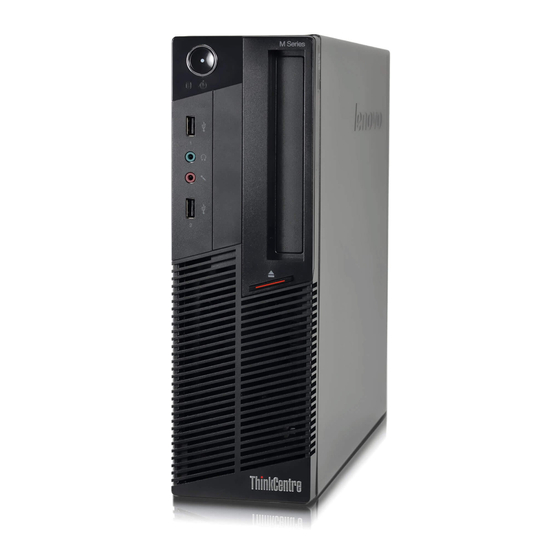
Locating connectors, controls, and indicators on the front of your computer Figure 1 “Front connector, control, and indicator locations” on page 80 shows the locations of the connectors, controls, and indicators on the front of your computer. © Copyright Lenovo 2011... - Page 86 Card reader (available in some models) Integrated microphones USB connector Power switch Headphone connector Brightness-up / Auto-adjusting control Microphone connector Brightness-down control USB connector VGA-in control Auto-adjusting control is enabled only while the computer is used in monitor mode. ThinkCentre Hardware Maintenance Manual...
-
Page 87: Using Your Computer In Monitor Mode
Using your computer in monitor mode Your computer can work in two modes: computer mode or monitor mode. This section provides instructions on how to use your computer in monitor mode. To use your computer in monitor mode, you need to have a second computer. Connect one end of the VGA cable to the VGA-in connector on the rear of your computer, and connect the other end to the VGA connector on the second computer. -
Page 88: Fru Locations
System stand hinge cover Foot stand Internal speaker System stand Computer cover Power supply System board shield window Rear I/O connector System board shield Internal speaker System fan Control button board Handle bar LCD panel Battery Foot stand ThinkCentre Hardware Maintenance Manual... - Page 89 Heat sink assembly (with a microprocessor underneath) Hard disk drive Memory module LCD bracket Microprocessor fan Optical drive System board VESA mount bracket Card reader Integrated camera Chapter 8 Replacing FRUs...
-
Page 90: System Board Parts And Connectors
Do not open your computer or attempt any repair before reading and understanding the “Important safety information” in the ThinkCentre Edge Safety and Warranty Guide that came with your computer. To obtain a copy of the ThinkCentre Edge Safety and Warranty Guide, go to: http://www.lenovo.com/support... - Page 91 CAUTION: Turn off the computer and wait three to five minutes to let the computer cool before removing the system stand hinge cover. To remove and reinstall the system stand hinge cover, do the following: 1. Remove any media from the drives and turn off all attached devices and the computer. 2.
-
Page 92: Removing And Reinstalling The System Stand
Do not open your computer or attempt any repair before reading and understanding the “Important safety information” in the ThinkCentre Edge Safety and Warranty Guide that came with your computer. To obtain a copy of the ThinkCentre Edge Safety and Warranty Guide, go to: http://www.lenovo.com/support... - Page 93 This section provides instructions on how to remove and reinstall the system stand. To remove and reinstall the system stand, do the following: 1. Turn off the computer and disconnect all power cords from electrical outlets. 2. Remove the system stand hinge cover. See “Removing and reinstalling the system stand hinge cover” on page 84.
-
Page 94: Removing And Reinstalling The Foot Stands
Do not open your computer or attempt any repair before reading and understanding the “Important safety information” in the ThinkCentre Edge Safety and Warranty Guide that came with your computer. To obtain a copy of the ThinkCentre Edge Safety and Warranty Guide, go to: http://www.lenovo.com/support... - Page 95 Figure 11. Removing each foot stand from the computer 7. To reinstall the foot stands, place each foot stand on the computer so that the screw hole aligns with the corresponding hole in the computer, and then reinstall the screw to secure each foot stand to the computer.
- Page 96 Figure 13. Reinstalling the rubber piece on each foot stand ThinkCentre Hardware Maintenance Manual...
-
Page 97: Removing The Computer Cover
Do not open your computer or attempt any repair before reading and understanding the “Important safety information” in the ThinkCentre Edge Safety and Warranty Guide that came with your computer. To obtain a copy of the ThinkCentre Edge Safety and Warranty Guide, go to: http://www.lenovo.com/support... - Page 98 ThinkCentre Edge Safety and Warranty Guide, go to: http://www.lenovo.com/support This section provides instructions on how to replace the hard disk drive. To replace the hard disk drive, do the following: 1. Remove all media from the drives and turn off all attached devices and the computer. Then, disconnect all power cords from electrical outlets and disconnect all cables that are connected to the computer.
-
Page 99: Replacing The Optical Drive
Replacing the optical drive Attention Do not open your computer or attempt any repair before reading and understanding the “Important safety information” in the ThinkCentre Edge Safety and Warranty Guide that came with your computer. To obtain a Chapter 8 Replacing FRUs... - Page 100 ThinkCentre Edge Safety and Warranty Guide, go to: http://www.lenovo.com/support This section provides instructions on how to replace the optical drive. Note: The optical drive is available only in some models. To replace the optical drive, do the following: 1.
-
Page 101: Removing The Vesa Mount Bracket
Do not open your computer or attempt any repair before reading and understanding the “Important safety information” in the ThinkCentre Edge Safety and Warranty Guide that came with your computer. To obtain a copy of the ThinkCentre Edge Safety and Warranty Guide, go to: http://www.lenovo.com/support... -
Page 102: Replacing The Rear I/O Assembly
Do not open your computer or attempt any repair before reading and understanding the “Important safety information” in the ThinkCentre Edge Safety and Warranty Guide that came with your computer. To obtain a copy of the ThinkCentre Edge Safety and Warranty Guide, go to: http://www.lenovo.com/support... - Page 103 To replace the rear I/O assembly, do the following: 1. Remove all media from the drives and turn off all attached devices and the computer. Then, disconnect all power cords from electrical outlets and disconnect all cables that are connected to the computer. 2.
-
Page 104: Removing And Reinstalling The System Board Shield
Do not open your computer or attempt any repair before reading and understanding the “Important safety information” in the ThinkCentre Edge Safety and Warranty Guide that came with your computer. To obtain a copy of the ThinkCentre Edge Safety and Warranty Guide, go to: http://www.lenovo.com/support... -
Page 105: Removing And Reinstalling The System Fan
Do not open your computer or attempt any repair before reading and understanding the “Important safety information” in the ThinkCentre Edge Safety and Warranty Guide that came with your computer. To obtain a copy of the ThinkCentre Edge Safety and Warranty Guide, go to: http://www.lenovo.com/support... -
Page 106: Replacing The Power Supply
Do not open your computer or attempt any repair before reading and understanding the “Important safety information” in the ThinkCentre Edge Safety and Warranty Guide that came with your computer. To obtain a copy of the ThinkCentre Edge Safety and Warranty Guide, go to: http://www.lenovo.com/support... - Page 107 1. Remove all media from the drives and turn off all attached devices and the computer. Then, disconnect all power cords from electrical outlets and disconnect all cables that are connected to the computer. 2. Place a soft, clean towel or cloth on the desk or other flat surface. Hold the sides of your computer and gently lay it down so that the screen is against the surface and the cover is facing up.
-
Page 108: Replacing The Microprocessor Fan
Do not open your computer or attempt any repair before reading and understanding the “Important safety information” in the ThinkCentre Edge Safety and Warranty Guide that came with your computer. To obtain a copy of the ThinkCentre Edge Safety and Warranty Guide, go to: http://www.lenovo.com/support... -
Page 109: Replacing The Heat Sink Assembly
Do not open your computer or attempt any repair before reading and understanding the “Important safety information” in the ThinkCentre Edge Safety and Warranty Guide that came with your computer. To obtain a copy of the ThinkCentre Edge Safety and Warranty Guide, go to: http://www.lenovo.com/support... -
Page 110: Replacing The Microprocessor
Do not open your computer or attempt any repair before reading and understanding the “Important safety information” in the ThinkCentre Edge Safety and Warranty Guide that came with your computer. To obtain a copy of the ThinkCentre Edge Safety and Warranty Guide, go to: http://www.lenovo.com/support... - Page 111 1. Remove all media from the drives and turn off all attached devices and the computer. Then, disconnect all power cords from electrical outlets and disconnect all cables that are connected to the computer. 2. Place a soft, clean towel or cloth on the desk or other flat surface. Hold the sides of your computer and gently lay it down so that the screen is against the surface and the cover is facing up.
- Page 112 10. Hold the new microprocessor and align the notches on it with the alignment keys in the microprocessor socket, or align the small triangle on one corner of the new microprocessor with the corresponding beveled corner of the microprocessor socket. ThinkCentre Hardware Maintenance Manual...
-
Page 113: Replacing The Card Reader
Do not open your computer or attempt any repair before reading and understanding the “Important safety information” in the ThinkCentre Edge Safety and Warranty Guide that came with your computer. To obtain a copy of the ThinkCentre Edge Safety and Warranty Guide, go to: http://www.lenovo.com/support... -
Page 114: Opening The System Board Shield Window
Do not open your computer or attempt any repair before reading and understanding the “Important safety information” in the ThinkCentre Edge Safety and Warranty Guide that came with your computer. To obtain a copy of the ThinkCentre Edge Safety and Warranty Guide, go to: http://www.lenovo.com/support... -
Page 115: Replacing The Battery
Do not open your computer or attempt any repair before reading and understanding the “Important safety information” in the ThinkCentre Edge Safety and Warranty Guide that came with your computer. To obtain a copy of the ThinkCentre Edge Safety and Warranty Guide, go to: http://www.lenovo.com/support... -
Page 116: Installing Or Replacing A Memory Module
Do not open your computer or attempt any repair before reading and understanding the “Important safety information” in the ThinkCentre Edge Safety and Warranty Guide that came with your computer. To obtain a copy of the ThinkCentre Edge Safety and Warranty Guide, go to: http://www.lenovo.com/support... - Page 117 Your computer has two memory slots for installing or replacing DDR3 SODIMMs (small outline dual inline memory modules). When installing or replacing a memory module, use 1 GB, 2 GB or 4 GB DDR3 SODIMMs in any combination up to a maximum of 8 GB of system memory. To install or replace a memory module, do the following: 1.
-
Page 118: Replacing The Internal Speakers
Do not open your computer or attempt any repair before reading and understanding the “Important safety information” in the ThinkCentre Edge Safety and Warranty Guide that came with your computer. To obtain a copy of the ThinkCentre Edge Safety and Warranty Guide, go to: http://www.lenovo.com/support... -
Page 119: Replacing The Integrated Camera
Do not open your computer or attempt any repair before reading and understanding the “Important safety information” in the ThinkCentre Edge Safety and Warranty Guide that came with your computer. To obtain a copy of the ThinkCentre Edge Safety and Warranty Guide, go to: http://www.lenovo.com/support... -
Page 120: Replacing The System Board
Do not open your computer or attempt any repair before reading and understanding the “Important safety information” in the ThinkCentre Edge Safety and Warranty Guide that came with your computer. To obtain a copy of the ThinkCentre Edge Safety and Warranty Guide, go to: http://www.lenovo.com/support... - Page 121 5. Locate the system board in the computer. See “FRU locations” on page 82. 6. Remove the heat sink assembly. See “Replacing the heat sink assembly” on page 103. 7. Remove the microprocessor. See “Replacing the microprocessor” on page 104. 8.
-
Page 122: Replacing The Lcd Panel
Do not open your computer or attempt any repair before reading and understanding the “Important safety information” in the ThinkCentre Edge Safety and Warranty Guide that came with your computer. To obtain a copy of the ThinkCentre Edge Safety and Warranty Guide, go to: http://www.lenovo.com/support... - Page 123 1. Remove all media from the drives and turn off all attached devices and the computer. Then, disconnect all power cords from electrical outlets and disconnect all cables that are connected to the computer. 2. Place a soft, clean towel or cloth on the desk or other flat surface. Hold the sides of your computer and gently lay it down so that the screen is against the surface and the cover is facing up.
- Page 124 13. Reinstall the foot stands. See “Removing and reinstalling the foot stands” on page 88. 14. Connect all the cables that were disconnected. See “System board parts and connectors” on page 84. 15. Go to “Completing the parts replacement” on page 120. ThinkCentre Hardware Maintenance Manual...
-
Page 125: Replacing The Wi-Fi Card
Do not open your computer or attempt any repair before reading and understanding the “Important safety information” in the ThinkCentre Safety and Warranty Guide that came with your computer. To obtain a copy of the ThinkCentre Safety and Warranty Guide, go to: http://www.lenovo.com/support... -
Page 126: Completing The Parts Replacement
2. Make sure that the cables are routed correctly before reinstalling the computer cover. Keep cables clear of the hinges and sides of the computer chassis to avoid interference with reinstalling the computer cover. ThinkCentre Hardware Maintenance Manual... - Page 127 Setup Utility program. Refer to Chapter 6 “Using the Setup Utility program” on page 53. Note: In most areas of the world, Lenovo requires the return of the defective Customer Replaceable Unit (CRU). Information about this will come with the CRU or will come a few days after the CRU arrives.
- Page 128 ThinkCentre Hardware Maintenance Manual...
-
Page 129: Chapter 9. Fru Lists
Optional-service CRU. Overall: MT 1729, 1731, 1732, 1734, 1736, 1737, 7074, 7075, 7077, 7078, 7556, and 7559 The Fru list below is for MTs: 1729, 1731, 1732, 1734, 1736, 1737, 7074, 7075, 7077, 7078, 7556, and 7559 © Copyright Lenovo 2011... - Page 130 • MT 7559: CTO B1B B3B B6V B7V E1Q E2Q E3Q F1Q H3J H4J J3G J4G Microprocessor, Ci3 2120 Sandy Bridge 3MB 2c FCLGA 3.3GHz 65W • MT 7074: CTO • MT 7075: CTO 03T8010 • MT 7077: CTO • MT 7078: CTO • MT 7556: CTO • MT 7559: CTO ThinkCentre Hardware Maintenance Manual...
- Page 131 Item # FRUs FRU # Microprocessor, Ci7 2600S Sandy Bridge 8MB 4c FCLGA 2.8GHZ 65W vPro • MT 7074: CTO B1J B2G B2M B2A B2H B2J B3M B4J • MT 7075: CTO 03T8015 • MT 7077: CTO B1G • MT 7078: CTO •...
- Page 132 G1U G1F G1S G2U G2F G2S 64Y6649 • MT 7077: CTO • MT 7078: CTO • MT 7556: CTO • MT 7559: CTO B1B B6V B7V B8V B9V D1V E1Q E2Q E3Q E9Q F1Q F2Q F3Q F7Q H1J H2J H3J H4J ThinkCentre Hardware Maintenance Manual...
- Page 133 Item # FRUs FRU # Memory module, 1GB PC3-10600 1333MHz DDR3 SoDIMM • MT 7074: CTO • MT 7075: CTO 64Y6650 • MT 7077: CTO • MT 7078: CTO • MT 7556: CTO • MT 7559: CTO Memory module, 2GB PC3-10600 1333MHz DDR3 SoDIMM •...
- Page 134 • MT 7559: CTO B1B B2B B3B B4B B5B B6V B7V B8V B9V D1V E1Q E2Q E3Q E4Q E5Q E6Q E7Q E8Q E9Q F1Q F2Q F3Q F4Q F5Q F6Q F7Q H1J H2J H3J H4J J1G J2G J3G J4G J5G J6G J7G ThinkCentre Hardware Maintenance Manual...
- Page 135 Item # FRUs FRU # Power supply, 180w 92+ • MT 7074: CTO B1J B2G B2M B2A B2H B2J B3M B4J B5A B5T B6A B6T B7A B7T B8A B8T • MT 7075: CTO 03T9023 • MT 7077: CTO B1G B2G B3G B4G B5G B6G B7G •...
- Page 136 • MT 7075: CTO B2M B6J B7J D2G D2M D2A D2H D2J D3G D3M D3A D3H D3J F4A F4H F4J G1U G1F G1S 45K0409 • MT 7077: CTO • MT 7078: CTO • MT 7556: CTO • MT 7559: CTO H1J H2J ThinkCentre Hardware Maintenance Manual...
- Page 137 Item # FRUs FRU # Hard disk drive, SATA 320G 7200RPM/6Gb • MT 7074: CTO B2G B2M B2A B2H B2J • MT 7075: CTO B2M B6J B7J D2G D2M D2A D2H D2J D3G D3M D3A D3H D3J F4A F4H F4J G1U G1F G1S 03T7040 •...
- Page 138 • MT 7559: CTO E6Q F4Q F5Q F6Q Integrated camera, 2.0M • MT 7074: all models • MT 7075: all models 03T9024 • MT 7077: all models • MT 7078: all models • MT 7556: all models • MT 7559: all models ThinkCentre Hardware Maintenance Manual...
-
Page 139: Mechanical Frus
Mechanical FRUs The FRUs listed in the following tables are not illustrated. Mechanical FRUs FRU # FRU, cable. converter panel FFC • MT 7074: all models • MT 7075: all models 03T7059 • MT 7077: all models • MT 7078: all models •... - Page 140 • MT 7559: all models FRU, converter for CMO • MT 7074: all models • MT 7075: all models 03T9036 • MT 7077: all models • MT 7078: all models • MT 7556: all models • MT 7559: all models ThinkCentre Hardware Maintenance Manual...
- Page 141 Mechanical FRUs FRU # FRU, converter for AUO • MT 7074: all models • MT 7075: all models 03T9037 • MT 7077: all models • MT 7078: all models • MT 7556: all models • MT 7559: all models FRU, converter for Samsung •...
- Page 142 FRU, cable. converter panel, Samsung • MT 7074: all models • MT 7075: all models 03T9664 • MT 7077: all models • MT 7078: all models • MT 7556: all models • MT 7559: all models ThinkCentre Hardware Maintenance Manual...
-
Page 143: Adapters And Miscellaneous Frus
Adapters and miscellaneous FRUs Adapters and miscellaneous FRUs FRU # L2-1000 condor peak • MT 7074: CTO • MT 7075: CTO 60Y3241 • MT 7077: CTO • MT 7078: CTO • MT 7556: CTO • MT 7559: CTO Cbt BCM43227 MOW M PCIE NB HMC •... -
Page 144: Keyboard And Mouse
• MT 7077: CTO B2G B3G B4G B5G B6G B7G • MT 7078: CTO B1G B2G B3G B4G B5G B6G • MT 7556: CTO B4G B5G B6G B7G B8G B9G • MT 7559: CTO J1G J2G J3G J4G J5G J6G J7G ThinkCentre Hardware Maintenance Manual... - Page 145 Keyboard - Slim USB FRU # Slim USB--Belgium/UK • MT 7074: CTO • MT 7075: CTO 54Y9297 • MT 7077: CTO B2G B3G B4G B5G B6G B7G • MT 7078: CTO B1G B2G B3G B4G B5G B6G • MT 7556: CTO B4G B5G B6G B7G B8G B9G •...
- Page 146 • MT 7556: CTO • MT 7559: CTO Slim USB--French Canadian • MT 7074: CTO • MT 7075: CTO G1F G2F 54Y9306 • MT 7077: CTO • MT 7078: CTO • MT 7556: CTO • MT 7559: CTO ThinkCentre Hardware Maintenance Manual...
- Page 147 Keyboard - Slim USB FRU # Slim USB--German • MT 7074: CTO • MT 7075: CTO 54Y9307 • MT 7077: CTO B2G B3G B4G B5G B6G B7G • MT 7078: CTO B1G B2G B3G B4G B5G B6G • MT 7556: CTO B4G B5G B6G B7G B8G B9G •...
- Page 148 • MT 7077: CTO B2G B3G B4G B5G B6G B7G • MT 7078: CTO B1G B2G B3G B4G B5G B6G • MT 7556: CTO B4G B5G B6G B7G B8G B9G • MT 7559: CTO J1G J2G J3G J4G J5G J6G J7G ThinkCentre Hardware Maintenance Manual...
- Page 149 Keyboard - Slim USB FRU # Slim USB--Polish • MT 7074: CTO • MT 7075: CTO 54Y9318 • MT 7077: CTO B2G B3G B4G B5G B6G B7G • MT 7078: CTO B1G B2G B3G B4G B5G B6G • MT 7556: CTO B4G B5G B6G B7G B8G B9G •...
- Page 150 • MT 7559: CTO J1G J2G J3G J4G J5G J6G J7G Slim USB--Thailand • MT 7074: CTO • MT 7075: CTO E7T E8T E9T F1T F2T 54Y9327 • MT 7077: CTO • MT 7078: CTO • MT 7556: CTO • MT 7559: CTO ThinkCentre Hardware Maintenance Manual...
- Page 151 Keyboard - Slim USB FRU # Slim USB--Turkish • MT 7074: CTO • MT 7075: CTO 54Y9328 • MT 7077: CTO B2G B3G B4G B5G B6G B7G • MT 7078: CTO B1G B2G B3G B4G B5G B6G • MT 7556: CTO B4G B5G B6G B7G B8G B9G •...
- Page 152 Full USB--US English • MT 7074: CTO • MT 7075: CTO F4A F4H D9A E1A E2A E4A 41A5289 • MT 7077: CTO • MT 7078: CTO • MT 7556: CTO • MT 7559: CTO F1Q F2Q F7Q ThinkCentre Hardware Maintenance Manual...
- Page 153 Keyboard - Preferred Pro USB Full size Keyboard FRU # Full USB--Arabic • MT 7074: CTO • MT 7075: CTO 41A5290 • MT 7077: CTO • MT 7078: CTO • MT 7556: CTO • MT 7559: CTO Full USB--Arabic/French • MT 7074: CTO •...
- Page 154 • MT 7078: CTO • MT 7556: CTO • MT 7559: CTO Full USB--Dutch • MT 7074: CTO • MT 7075: CTO 41A5299 • MT 7077: CTO • MT 7078: CTO • MT 7556: CTO • MT 7559: CTO ThinkCentre Hardware Maintenance Manual...
- Page 155 Keyboard - Preferred Pro USB Full size Keyboard FRU # Full USB--French • MT 7074: CTO • MT 7075: CTO 41A5300 • MT 7077: CTO • MT 7078: CTO • MT 7556: CTO • MT 7559: CTO Full USB--French Canadian •...
- Page 156 • MT 7078: CTO • MT 7556: CTO • MT 7559: CTO Full USB--Italy • MT 7074: CTO • MT 7075: CTO 41A5309 • MT 7077: CTO • MT 7078: CTO • MT 7556: CTO • MT 7559: CTO ThinkCentre Hardware Maintenance Manual...
- Page 157 Keyboard - Preferred Pro USB Full size Keyboard FRU # Full USB--Japanese • MT 7074: CTO • MT 7075: CTO F4J D5J D6J 41A5310 • MT 7077: CTO • MT 7078: CTO • MT 7556: CTO B2J B3J • MT 7559: CTO H1J H2J H3J H4J Full USB--Korean •...
- Page 158 • MT 7078: CTO • MT 7556: CTO • MT 7559: CTO Full USB--Serbian/Cyrillic • MT 7074: CTO • MT 7075: CTO 41A5319 • MT 7077: CTO • MT 7078: CTO • MT 7556: CTO • MT 7559: CTO ThinkCentre Hardware Maintenance Manual...
- Page 159 Keyboard - Preferred Pro USB Full size Keyboard FRU # Full USB--Slovak • MT 7074: CTO • MT 7075: CTO 41A5320 • MT 7077: CTO • MT 7078: CTO • MT 7556: CTO • MT 7559: CTO Full USB--Spanish • MT 7074: CTO •...
- Page 160 • MT 7556: CTO • MT 7559: CTO Full USB-- Slovenian +++ • MT 7074: CTO • MT 7075: CTO 41A5329 • MT 7077: CTO • MT 7078: CTO • MT 7556: CTO • MT 7559: CTO ThinkCentre Hardware Maintenance Manual...
- Page 161 Keyboard - Preferred Pro USB Full size Keyboard FRU # Full USB--Arabic (New) • MT 7074: CTO • MT 7075: CTO 45J4880 • MT 7077: CTO • MT 7078: CTO • MT 7556: CTO • MT 7559: CTO Full USB--Lithuanian •...
- Page 162 • MT 7559: CTO Wireless edge keyboard and mouse--Chinese/US/Taiwanese • MT 7074: CTO • MT 7075: CTO 03X8208 • MT 7077: CTO • MT 7078: CTO • MT 7556: CTO • MT 7559: CTO B4B B5B B9V ThinkCentre Hardware Maintenance Manual...
- Page 163 Wireless edge keyboard and mouse FRU # Wireless edge keyboard and mouse--Czech (QWERTY or ABB) • MT 7074: CTO B2G • MT 7075: CTO D2G 03X8209 • MT 7077: CTO B1G • MT 7078: CTO • MT 7556: CTO • MT 7559: CTO Wireless edge keyboard and mouse--Danish •...
- Page 164 • MT 7559: CTO Wireless edge keyboard and mouse--Hebrew • MT 7074: CTO B2G • MT 7075: CTO D2G 03X8218 • MT 7077: CTO B1G • MT 7078: CTO • MT 7556: CTO • MT 7559: CTO ThinkCentre Hardware Maintenance Manual...
- Page 165 Wireless edge keyboard and mouse FRU # Wireless edge keyboard and mouse--Hungarian • MT 7074: CTO B2G • MT 7075: CTO D2G 03X8219 • MT 7077: CTO B1G • MT 7078: CTO • MT 7556: CTO • MT 7559: CTO Wireless edge keyboard and mouse--Iceland •...
- Page 166 • MT 7559: CTO Wireless edge keyboard and mouse--Russian/Cy US • MT 7074: CTO B2G • MT 7075: CTO D2G 03X8228 • MT 7077: CTO B1G • MT 7078: CTO • MT 7556: CTO • MT 7559: CTO ThinkCentre Hardware Maintenance Manual...
- Page 167 Wireless edge keyboard and mouse FRU # Wireless edge keyboard and mouse--Slovak • MT 7074: CTO B2G • MT 7075: CTO D2G 03X8229 • MT 7077: CTO B1G • MT 7078: CTO • MT 7556: CTO • MT 7559: CTO Wireless edge keyboard and mouse--Spanish •...
- Page 168 • MT 7559: CTO Wireless edge keyboard and mouse--Brazil/Portuguese (without battery) • MT 7074: CTO B2G • MT 7075: CTO D2G 03X8206 • MT 7077: CTO B1G • MT 7078: CTO • MT 7556: CTO • MT 7559: CTO ThinkCentre Hardware Maintenance Manual...
-
Page 169: Power Cords
Mice FRU # Lenovo Enhanced Optical USB mouse • MT 7074: CTO • MT 7075: CTO B2M B4M B6J B7J F4A F4H F4J D4M D5J D6J D9A E1A E2A E4A E7T E8T E9T F1T F2T G1U G1F G1S G2U G2F G2S 45J4889 •... - Page 170 • MT 7559: CTO B1B B2B B3B B4B B5B J1G J2G J3G J4G J5G J6G J7G Line cord-Taiwan • MT 7074: CTO • MT 7075: CTO 41R3278 • MT 7077: CTO • MT 7078: CTO • MT 7556: CTO • MT 7559: CTO B6V B7V B8V B9V D1V ThinkCentre Hardware Maintenance Manual...
- Page 171 Power Cords FRU # Line cord-Italy • MT 7074: CTO B2G • MT 7075: CTO D2G D3G G1S G2S 41R3232 • MT 7077: CTO B1G B2G B3G B4G B5G B6G B7G • MT 7078: CTO B1G B2G B3G B4G B5G B6G •...
- Page 172 • MT 7075: CTO B6J B7J B8J D2J D3J F4J D5J D6J D7J D8J 41R3249 • MT 7077: CTO • MT 7078: CTO • MT 7556: CTO B2J B3J • MT 7559: CTO H1J H2J H3J H4J ThinkCentre Hardware Maintenance Manual...
- Page 173 Power Cords FRU # Line cord-Brazil • MT 7074: CTO • MT 7075: CTO 41R3271 • MT 7077: CTO • MT 7078: CTO • MT 7556: CTO • MT 7559: CTO Line cord-LA (High Voltage) Argentina, Paraguay and Uruguay • MT 7074: CTO •...
- Page 174 • MT 7077: CTO B1G B2G B3G B4G B5G B6G B7G • MT 7078: CTO B1G B2G B3G B4G B5G B6G • MT 7556: CTO B4G B5G B6G B7G B8G B9G • MT 7559: CTO J1G J2G J3G J4G J5G J6G J7G ThinkCentre Hardware Maintenance Manual...
-
Page 175: Windows 7 Home Basic 32 Recovery Cd
Power Cords FRU # Line cord-South Africa • MT 7074: CTO B2G B2M B2A B5A B6A B7A B8A • MT 7075: CTO B2M B3M B4M B5M B9A D1A D2G D2M D2A D3G D3M D3A D4M D9A E1A E2A E4A E5A E6A 41R3221 •... -
Page 176: Windows 7 Home Premium 32 Recovery Cd
• MT 7078: CTO • MT 7556: CTO • MT 7559: CTO Spanish • MT 7074: CTO • MT 7075: CTO 03T0948 • MT 7077: CTO • MT 7078: CTO • MT 7556: CTO • MT 7559: CTO ThinkCentre Hardware Maintenance Manual... - Page 177 Windows 7 Home Premium 32 FRU # French • MT 7074: CTO • MT 7075: CTO 03T0938 • MT 7077: CTO • MT 7078: CTO • MT 7556: CTO • MT 7559: CTO Italian • MT 7074: CTO • MT 7075: CTO 03T0942 •...
- Page 178 • MT 7078: CTO • MT 7556: CTO • MT 7559: CTO Hebrew • MT 7074: CTO • MT 7075: CTO 03T0940 • MT 7077: CTO • MT 7078: CTO • MT 7556: CTO • MT 7559: CTO ThinkCentre Hardware Maintenance Manual...
-
Page 179: Windows 7 Home Premium 64 Recovery Cd
Windows 7 Home Premium 32 FRU # Portuguese • MT 7074: CTO • MT 7075: CTO 03T0946 • MT 7077: CTO • MT 7078: CTO • MT 7556: CTO • MT 7559: CTO India English • MT 7074: CTO • MT 7075: CTO 03T0937 •... - Page 180 • MT 7078: CTO • MT 7556: CTO • MT 7559: CTO Polish • MT 7074: CTO • MT 7075: CTO 03T0958 • MT 7077: CTO • MT 7078: CTO • MT 7556: CTO • MT 7559: CTO ThinkCentre Hardware Maintenance Manual...
-
Page 181: Windows 7 Professional 32 Recovery Cd
Windows 7 Home Premium 64 FRU # Hebrew • MT 7074: CTO • MT 7075: CTO 03T0955 • MT 7077: CTO • MT 7078: CTO • MT 7556: CTO • MT 7559: CTO Portuguese • MT 7074: CTO • MT 7075: CTO 03T0959 •... - Page 182 • MT 7078: CTO • MT 7556: CTO • MT 7559: CTO Italian • MT 7074: CTO • MT 7075: CTO 03T0970 • MT 7077: CTO • MT 7078: CTO • MT 7556: CTO • MT 7559: CTO ThinkCentre Hardware Maintenance Manual...
- Page 183 Windows 7 Professional 32 FRU # German • MT 7074: CTO • MT 7075: CTO 03T0967 • MT 7077: CTO • MT 7078: CTO • MT 7556: CTO • MT 7559: CTO C&L EMEA (EN FR GR IT NL) • MT 7074: CTO •...
- Page 184 • MT 7078: CTO • MT 7556: CTO • MT 7559: CTO India English • MT 7074: CTO • MT 7075: CTO 03T0965 • MT 7077: CTO • MT 7078: CTO • MT 7556: CTO • MT 7559: CTO ThinkCentre Hardware Maintenance Manual...
-
Page 185: Windows 7 Professional 64 Recovery Cd
Windows 7 Professional 64 Recovery CD Windows 7 Professional 64 FRU # English • MT 7074: CTO B2G B2M B2A B2H B3M • MT 7075: CTO B2M B3M B5M D2G D2M D2A D2H D3G D3M D3A D3H G2U 03T1001 • MT 7077: CTO B1G B3G B5G B7G •... - Page 186 • MT 7075: CTO D2G D3G 03T0980 • MT 7077: CTO B1G B3G B5G B7G • MT 7078: CTO B2G B4G B6G • MT 7556: CTO B5G B7G B9G • MT 7559: CTO J2G J5G J7G ThinkCentre Hardware Maintenance Manual...
- Page 187 Windows 7 Professional 64 FRU # Chinese-Traditional (Taiwan) • MT 7074: CTO • MT 7075: CTO 03T0981 • MT 7077: CTO • MT 7078: CTO • MT 7556: CTO • MT 7559: CTO B6V D1V Polish • MT 7074: CTO B2G •...
- Page 188 • MT 7075: CTO D2G D3G 03T0982 • MT 7077: CTO B1G B3G B5G B7G • MT 7078: CTO B2G B4G B6G • MT 7556: CTO B5G B7G B9G • MT 7559: CTO J2G J5G J7G ThinkCentre Hardware Maintenance Manual...
- Page 189 Windows 7 Professional 64 FRU # Slovakian • MT 7074: CTO B2G • MT 7075: CTO D2G D3G 03T0996 • MT 7077: CTO B1G B3G B5G B7G • MT 7078: CTO B2G B4G B6G • MT 7556: CTO B5G B7G B9G •...
- Page 190 ThinkCentre Hardware Maintenance Manual...
-
Page 191: Chapter 10. Additional Service Information
– Start the Setup Utility. – Select Standard CMOS Features. • Sources for obtaining the latest level BIOS available 1. Lenovo support web site: http://www.lenovo.com/support/ 2. Lenovo Customer Support Center 3. Levels 1 and 2 Support To update (flash) the BIOS, see “Flash update procedures” on page 185. -
Page 192: Updating (Flashing) The Bios From Your Operating System
Updating (flashing) the BIOS from your operating system Note: Because Lenovo makes constant improvements to its Web sites, the Web page contents are subject to change without notice, including the contents referenced in the following procedure. -
Page 193: Power Management
4. Move the jumper from the standard position (pin 1 and pin 2) to the maintenance position (pin 2 and pin 3). 5. Install the computer cover and reconnect all cables and power cords that were disconnected. See “Completing the parts replacement” on page 120. 6. - Page 194 ThinkCentre Hardware Maintenance Manual...
-
Page 195: Appendix A. Notices
Lenovo representative for information on the products and services currently available in your area. Any reference to a Lenovo product, program, or service is not intended to state or imply that only that Lenovo product, program, or service may be used. Any functionally equivalent product, program, or service that does not infringe any Lenovo intellectual property right may be used instead. -
Page 196: Television Output Notice
Macrovision Corporation. Reverse engineering or disassembly is prohibited. European conformance CE mark Trademarks The following terms are trademarks of Lenovo in the United States, other countries, or both: Lenovo The Lenovo logo Rescue and Recovery ThinkVantage Microsoft and Windows are trademarks of the Microsoft group of companies. -
Page 197: Index
I/O assembly, replacing recovering a POST/BIOS update failure recovery hard disk drive, replacing boot-block heat sink assembly, replacing removing system board shield system fan VESA mount bracket information removing computer cover resources removing the foot stand © Copyright Lenovo 2011... - Page 198 BIOS, updating (flashing) 185–186 trademarks troubleshooting, basic troubleshooting, diagnostics updating (flashing) the BIOS ThinkCentre Hardware Maintenance Manual...
- Page 200 Part Number: 0A96894 Printed in USA (1P) P/N: 0A96894 *0A96894*...