Advertisement
Table of Contents
-
1
Location: Back Panel
- 1.1 Table of Contents
- 1.2 Means that There Is no Danger of Hazardous Radiation Outside
- 1.3 The Marking this Product Has Been Classified as Class 1. It
- 1.4 The Product
- 1.5 Parts Descriptions
- 1.6 Pc Board
- 1.7 Schematic Diagram
- 1.8 Component Side View
- 1.9 Exploded View
- 1.10 Power Supply
- 1.11 Parts List
- 1.12 Specifications
- 2 Laser Product
- Download this manual
DVD AV CONTROL CENTER
DVR-6300
SERVICE MANUAL
(DVT-6300/7300/8300)
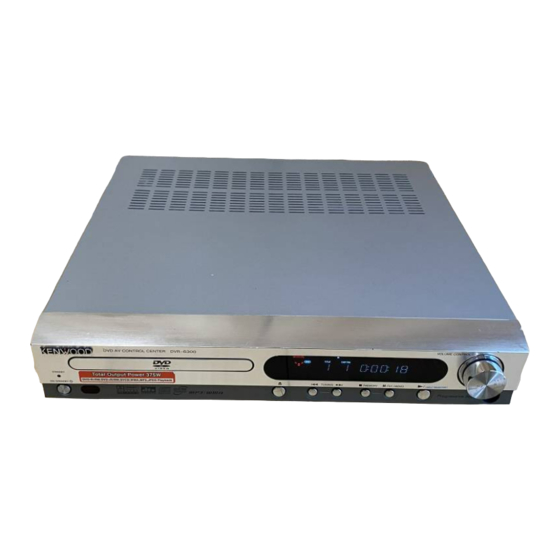
Panel ass'y *
(A60-)
POWER
Cabinet
(A01-3942-08)
Terminal block
(E70-1003-08)
* Refer to parts list on page 27.
In compliance with Federal Regulations, following are repro-
duction of labels on, or inside the product relating to laser
product safety.
Caution : No connection of ground line if disassemble
the unit. Please connect the ground line on
rear panel, PCBs, Chassis and some others.
Door
(A29-1243-08)
Jack RCA
(E59-0001-08)
Jack RCA *
(E63-)
KENWOOD Corp. certifies this equipment conforms to DHHS
Regulations No.21 CFR 1040. 10, Chapter 1, subchapter J.
DANGER : Laser radiation when open and interlock defeated.
AVOID DIRECT EXPOSURE TO BEAM.
© 2004-8 PRINTED IN KOREA
B51-5922-00 (K/K) 746
Knob
(K29-8412-08)
Fiber opt jack
Tuner *
(W02-4590-08)
(W02-)
Phone jack
(E11-0989-08)
70%
Advertisement
Table of Contents

Related Manuals for Kenwood DVR-6300


Summary of Contents for Kenwood DVR-6300
- Page 1 * Refer to parts list on page 27. In compliance with Federal Regulations, following are repro- KENWOOD Corp. certifies this equipment conforms to DHHS duction of labels on, or inside the product relating to laser Regulations No.21 CFR 1040. 10, Chapter 1, subchapter J.
-
Page 2: Table Of Contents
HACHIOJI-SHI, TOKYO, JAPAN tion has dried up. Be specially cautious against condensation in the following circum- KENWOOD CORP. CERTIFIES THIS EQUIPMENT CONFORMS TO DHHS REGULATIONS NO. 21 CFR stances: 1040.10, CHAPTER 1, SUBCHAPTER J. When this unit is carried from one place to another across a large... -
Page 3: Parts Descriptions
DVR-6300 PARTS DESCRIPTIONS CAPACITORS • Capacitor value CC 45 TH 1H 220 J Color* CC45 010 = 1pF 0 = 22pF 100 = 10pF 1 = Type ... ceramic, electrolytic, etc. 4 = Voltage rating Multiplier 2 = Shape ... round, square, ect. -
Page 4: Pc Board
PC BOARD(Component side view) SMPS CN902 CN901 W917 W931 C952 C953 W912 IC921 IC922 W930 C929 W929 FH900B PN901 C935 IC923 C951 C930 L923 C924 F901 W910 C944 D933 Q921 C954 C942 VR901 D951 FH900A W909 R900 C923 C943 C927 C926 CM901 C941... -
Page 5: Schematic Diagram
PC BOARD(Component side view) C6A5 C6A6 C5C9 C5C2 C5C8 C5E0 C5C3 R6A5 JK6A1 R5A7 R5C1 Q501 R5A8 C569 R5E1 IC5A1 R5C2 R5A9 R526 R616 C592 R5C3 C5C4 R5E2 IC5C1 R5C9 R6A3 C5C5 R5C4 ZD6A3 JK6A2 R5E0 R5C5 C5C7 C503 TP551 C502 R5C6 C516... - Page 6 PC BOARD(Foil side view) TP522 TP510 TP520 TP523 TP524 TP526 TP528 TP540 TP530 TP533 TP542 TP535 TP541 TP511 TP512 TP509 TP532 TP531 TP203 TP202 TP201 TP204 TP226 TP559 TP225 TP205 Refer to the schematic diagram for the value of resistors and capacitors.
- Page 7 PC BOARD(Component side view) MAIN PN901 PN902 R324 L700 C981 L309 L303 PN101 PN102 L308 L304 L307 L302 L306 C338 C322 L311 C341 C583 R583 C562 Q504 C973 R326 C975 C314 C329 C313 R327 C557 C312 R328 C561 C515 IC301 R329 R319 C564...
- Page 8 PC BOARD(Foil side view) MAIN Refer to the schematic diagram for the value of resistors and capacitors.
-
Page 9: Component Side View
PC BOARD PHONES VFD001 VR001 C001 Component side view R024 JK001 R023 FRONT R025 Q001 C005 LD001 PN002 R021 C008 C002 R050 C004 SKIP+/SEARCH+ R032 R030 PRESET+ R029 R028 PN002 SW002 SW007 SW006 SW005 SW004 SW003 SW001 R027 R026 RMC001 C003 L001 PAUSE... - Page 10 DVR-6300 PICKUP 1 2 3 4 PDM01 R209 0 DOWN HFM VCC LOAD RF OUT L201 LD DVD R207 MD DVD 10uH VR DVD +3.3V +3.3V TP205 GND PD C202 0.1 C255 C253 VREF C203 0.1 L202 C575 AVDDP IC505...
- Page 11 R526 TP554 Q501 1.8K 47u16 MRESET R523 TP555 DVD CLK L501 +3.3V +3.3V +3.3V +3.3V +3.3V +3.3V +2.5V +2.5V PDA01 GND(A) L604 L603 +3.3V +3.3V 3.3V SMPS- +3.3V CN903 GND(D) +2.5V +2.5V 2.5V +8V(M) GND(M) AT-2 DVR-6300(M) (1/4) DVD (2/2)
- Page 12 DVR-6300 R531 68K R224 C526 56P IC501(/2) R533 C535 R539 R521 C524 10u35 100u16 R535 C536 R540 R334 10u35 R523 1.2K R534 47K Q501 R582 C301 C528 47P C342 L310 C302 Q502 C529 47P +2.5V 0.01 C341 R537 47K L300...
- Page 13 SIGNAL LINE C896 6800P GND LINE nal input. The measurement L210 B LINE value may vary depending on the B LINE measuring instruments used or L208 on the product. +3.3V +3.3V +33V +33V WOOFER +12VA +12VA CENTER DVR-6300 (2/4) MAIN (2/2)
- Page 14 4G 3G The DC voltage is an actual reading measured with a high impedance type voltmeter with no signal input. The mea- surement value may vary depending on the measuring instruments used or on the product. (2G-11G) (12G) DVR-6300 (3/4) FRONT...
- Page 15 T3.15L 250V AC110-120V/220-240V~ 50/60Hz FH900A FH900B DVR-6300 (4/4) CAUTION: For continued safety, replace safety critical components only The DC voltage is an actual reading measured with a high with manufacturer's recommended parts (refer to parts list). indicates impedance type voltmeter with no signal input. The mea- safety critical components.
-
Page 16: Exploded View
DVR-6300 EXPLODED VIEW (MECHANISM) N09-5539-08 φ2x6(TP) N09-5540-08 φ2x6(BLK) N89-2006-45 φ1.7x6 N09-5541-08 φ2x4 N84-2004-46 M2x3 N30-2003-46 DVR-6300 Parts with exploded numbers larger than 700 are not supplied. - Page 17 J K601 JK200 φ3x10(BLK) : N89-3010-45 φ3x10 : N89-3010-46 SPEAKERS φ3x8 : N89-3008-46 J K700 φ3x16 : N89-3016-46 PHONES JK0 01 VOLUME VFD001 CONTROL VR001 POWER TUNING /MEMORY /ST./MONO /(INPUT SELECTOR) ON/STANDBY SW007 SW006 SW005 SW004 SW003 SW002 SW001 DVR-6300...
-
Page 18: Power Supply
Parts No. Description Ref. No Parts No. ress Parts nation marks Parts nation marks ress C932 CE04KW0J102M ELECTRO 1000UF 6.3WV DVR-6300 C933 CE04KW1C222M ELECTRO 2200UF 16WV C934 CE04KW0J102M ELECTRO 1000UF 6.3WV ✻ B60-5526-08 INSTRUCTION AS 3835RH0040B C935 CE04KW1C470M ELECTRO 47UF 16WV ✻... - Page 19 ✽ New Parts ✽ New Parts Parts without Parts No. are not supplied. Parts without Parts No. are not supplied. Les articles non mentionnes dans le Parts No. ne sont pas fournis. Les articles non mentionnes dans le Parts No. ne sont pas fournis. Teile ohne Parts No.
- Page 20 ✽ New Parts ✽ New Parts Parts without Parts No. are not supplied. Parts without Parts No. are not supplied. Les articles non mentionnes dans le Parts No. ne sont pas fournis. Les articles non mentionnes dans le Parts No. ne sont pas fournis. Teile ohne Parts No.
- Page 21 ✽ New Parts ✽ New Parts Parts without Parts No. are not supplied. Parts without Parts No. are not supplied. Les articles non mentionnes dans le Parts No. ne sont pas fournis. Les articles non mentionnes dans le Parts No. ne sont pas fournis. Teile ohne Parts No.
- Page 22 ✽ New Parts ✽ New Parts Parts without Parts No. are not supplied. Parts without Parts No. are not supplied. Les articles non mentionnes dans le Parts No. ne sont pas fournis. Les articles non mentionnes dans le Parts No. ne sont pas fournis. Teile ohne Parts No.
- Page 23 ✽ New Parts ✽ New Parts Parts without Parts No. are not supplied. Parts without Parts No. are not supplied. Les articles non mentionnes dans le Parts No. ne sont pas fournis. Les articles non mentionnes dans le Parts No. ne sont pas fournis. Teile ohne Parts No.
-
Page 24: Parts List
PX/AAFES MODEL ABB. ✻ E35-3730-08 CABLE,FLAT 6850R-GK12A ✻ A13-3230-08 FRAME 3210R-M002A ✻ E35-3731-08 CABLE,FLAT 6850R-JW14B ✻ 2A,2B J02-1571-08 RUBBER 5040R-0075D DVR-6300 D16-0805-08 BELT 4400R-0006B ✻ D13-2651-08 GEAR 4470R-0055A ✻ D13-2652-08 GEAR 4470R-0056A ✻ J90-1402-08 GUIDE 4974R-0023A ✻ A10-3622-08 BASE 3040R-D001A ✻... -
Page 25: Specifications
Speaker configuration ....... 50 mm (2”), cone type Impedance ................8 Ω Impedance ................8 Ω Power Handling Capacity (DVR-6300) ......60 W Power Handling Capacity (DVR-6300) ......60 W Dimensions ..........W: 124 mm (4-7/8”) Dimensions ..........W: 80 mm (3-1/8”) H: maximum 337 mm (13-1/4”) -
Page 26: Main Unit
(for U.S.A. and Canada) Y-signal ............1 Vp-p /75 ‰ -signal .......... 0.7 Vp-p /75 ‰ RGB output (SCAR T) (for Europe) ....0.7 Vp-p /75 ‰ KENWOOD follows a policy of continuous advancements in development. For this reason specifications may Notes Notes Notes be changed without notice.