Table of Contents
Advertisement
SERVICE MANUAL
Ver 1.0 2000. 01
Dolby noise reduction manufactured under license
from Dolby Laboratories Licensing Corporation.
"DOLBY" and the double-D symbol ; are trade-
marks of Dolby Laboratories Licensing Corporation.
• Frequency response (Dolby NR off (WM-EX505))
• Output
i
• Power requirements
• Dimensions (w/h/d)
• Mass
• Supplied accessories
MICROFILM
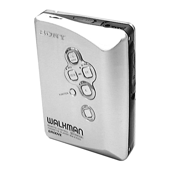
WM-EX500/EX505
Photo: WM-EX505
SPECIFICATIONS
Model Name Using Similar Mechanism
Tape Transport Mechanism Type
Battery life (Approx. hours)
Sony alkaline LR6 (SG)
Note
CASSETTE PLAYER
AEP Model
WM-EX500/EX505
E Model
WM-EX505
NEW
MT-WMEX505-162
Advertisement
Table of Contents

Related Manuals for Sony Walkman WM-EX500


Summary of Contents for Sony Walkman WM-EX500
- Page 1 “DOLBY” and the double-D symbol ; are trade- marks of Dolby Laboratories Licensing Corporation. SPECIFICATIONS • Frequency response (Dolby NR off (WM-EX505)) Battery life (Approx. hours) Sony alkaline LR6 (SG) • Output • Power requirements • Dimensions (w/h/d) Note • Mass •...
-
Page 2: Table Of Contents
TABLE OF CONTENTS Flexible Circuit Board Repairing • Keep the temperature of the soldering iron around 270 ˚C dur- ing repairing. SERVICING NOTES ..........3 • Do not touch the soldering iron on the same conductor of the circuit board (within 3 times). GENERAL .............. -
Page 3: Servicing Notes
SECTION 1 SERVICING NOTES This set detects the rotation of the idler gear (A) (side S) using the 3. FF, REW modes PH701 (photo reflector). The PH701 is mounted on the MAIN (1) Check that the preset state is set. board, therefore the idler gear (A) (side S) cannot be detected with (2) Input the square wave or sine wave to the TP36 (PHOTO IN) the MAIN board removed. - Page 4 SLIDER (NRA) Rotation system Rotation system during PLAY gear (NR) (FWD: left side REW: right side) idler (A) gear (T side) idler (A) gear (S side) gear (REEL) (S side) gear (REEL) (T side) slider (NRA) motor pulley cam gear clutch assy (F) gear (Y) side F side R...
-
Page 5: General
SECTION 2 This section is extracted from instruction manual. GENERAL BATT OPEN (WM-EX500) HOLD FF (AMS• BL SKIP/s) Y•REPEAT OPEN REW(AMS•AVLS) FUNCTION SOUND (WM-EX505) Plug in firmly. Branchez fermement. Y•x HOLD FF (AMS• HOLD Y•REPEAT BL SKIP/s) REW (AMS•AVLS) x•;NR... -
Page 6: Disassembly
SECTION 3 DISASSEMBLY • This set can be disassembled in the order shown below. Lid Assy, Holder, Battery Main Board/Note for Installation Cassette Belt Motor (Capstan/Reel) (M901) Case Assy Ornament Assy Holder (FS) Assy Lever (N/R) Assy, Pinch Head, Magnetic (HP901) Note: Follow the disassembly procedure in the numerical order given. - Page 7 CASE ASSY 2 case assy 1 three screws (M1.4 3.0) 1 two screws (M1.4 3.0) ORNAMENT ASSY 1 two claws 1 claw 2 ornament assy knob (hold) On installation reel ornament, adjust the S707 and knob (hold). S707 – 7 –...
- Page 8 HOLDER, BATTERY 2 two screws (M1.7 4.5) 3 battery holder 1 Break the soldering 1 Break the soldering of battery terminal (–). of battery terminal (+). BELT 1 belt (See page 4) – 8 –...
-
Page 9: Main Board
MAIN BOARD 2 screw (M1.4 2.0) 1 Remove four solders of motor. flexible board 1 Remove two solders of plunger solenoid. 1 Remove six solders of flexible board. 1 Remove four solders of leaf switch. 3 MAIN board NOTE FOR INSTALLATION •... - Page 10 MOTOR (CAPSTAN/REEL) (M901) 1 two screws (M1.4) 2 motor (M901) HOLDER (FS) ASSY 2 boss 7 bracket (cassette) assy 5 lock lever (S) 3 lock lever (B) 1 two screws (M1.4 1.4) 4 screw (M1.4) 6 boss 9 Remove the holder (FS) assy to direction of the arrow.
- Page 11 LEVER (N/R) ASSY, PINCH 1 claw 2 Remove the pinch lever (R) assy to direction of the arrow. 4 Remove the pinch lever (N) assy to direction of the arrow. 3 claw HEAD, MAGNETIC (HP901) 1 claw 2 Remove the magnetic head to direction of the arrow.
-
Page 12: Mechanical Adjustments
SECTION 4 SECTION 5 MECHANICAL ADJUSTMENTS ELECTRICAL ADJUSTMENTS PRECAUTION PRECAUTION 1. Clean the following parts with a denatured-alcohol-moistened 1. Specified voltage : 1.3 V (DC) swab: 2. Setting playback head pinch roller BL SKIP : OFF rubber belts capstan SOUND NORM/MB/GRV : NORM 2. -
Page 13: Diagrams
WM-EX500/EX505 SECTION 6 DIAGRAMS 6-1. BLOCK DIAGRAM • SIGNAL PATH (EX500) RIPPLE FILTER : PLAYBACK BATT B+ Q301 AUDIO MASTER AMP AUDIO MASTER AMP R-CH: Same as L-CH IC301 (1/2) IC301 (2/2) RF OUT BASE HP901 J301 RV301 (PLAYBACK) DOLBY NR... -
Page 14: Printed Wiring Board
WM-EX500/EX505 6-2. PRINTED WIRING BOARD • Semiconductor Location J301 i REMOTE Ref. No. Location D701 E-16 D702 MAIN BOARD (SIDE A) MAIN BOARD (SIDE B) D703 H-13 D704 G-13 RV301 D705 F-12 Q301 R302 C203 EXCEPT EXCEPT D706 E-13 –2... -
Page 15: Schematic Diagram
WM-EX500/EX505 6-3. SCHEMATIC DIAGRAM • See page 20 for IC Block Diagrams. • Waveforms 1 IC702 4 LX 1 V/DIV, 5 µs/DIV 3 Vp-p 10 s 2 IC601 5 OSC, IC701 5 OSC IN 20 mV/DIV, 1 ms/DIV 23.2 mVp-p 1.7 ms... -
Page 16: 6-4. Ic Pin Function Description
Dolby is present or not control terminal OUT A – BEEP 39 BEEP “L”: dolby is not present (WM-EX500), “H”: dolby is present (WM-EX505) AMS OUT 40 PHOTO IN Rotation detect signal input of the capstan/reel motor (M901) RIPPLE BASE AVSS —... - Page 17 Pin No. Pin Name Description Motor direction control signal output to the capstan/reel motor drive (IC601) MOTOR DIR “L”: counterclockwise, “H”: clockwise Motor speed control signal output to the capstan/reel motor drive (IC601) SPEED CTL “L”: normal speed, “H”: 1/2 speed MUTE Power on mute control signal output to the TA2123FA (IC301) “L”: mute on VSS1...
-
Page 18: Exploded Views
SECTION 7 EXPLODED VIEWS NOTE: • -XX and -X mean standardized parts, so they • Items marked “*” are not stocked since they are seldom required for routine service. Some may have some difference from the original one. delay should be anticipated when ordering •... - Page 19 (2) MECHANISM DECK SECITON (MT-WMEX505-162) M901 PM901 HP901 Ref. No. Part No. Description Remark Ref. No. Part No. Description Remark X-3378-354-1 HOLDER (FS) ASSY 3-007-433-01 SHEET (N), REFLECTION X-3377-363-1 LEVER (R) ASSY, PINCH X-3378-107-1 CHASSIS (FB) ASSY 3-046-789-01 SPRING (HDA) 3-010-274-02 TABLE, REEL X-3377-362-1 LEVER (N) ASSY, PINCH 3-010-954-01 SPRING (BT), COMPRESSION...
-
Page 20: Electrical Parts List
SECTION 8 MAIN ELECTRICAL PARTS LIST NOTE: When indicating parts by reference • Due to standardization, replacements in the • Items marked “*” are not stocked since they number, please include the board. parts list may be different from the parts speci- are seldom required for routine service. - Page 21 MAIN Ref. No. Part No. Description Remark Ref. No. Part No. Description Remark < FERRITE BEAD > R114 1-216-821-11 METAL CHIP 1/16W FB101 1-469-125-21 FERRITE BEAD (EXCEPT FRENCH) R150 1-216-807-11 RES, CHIP 1/16W FB201 1-469-125-21 FERRITE BEAD (EXCEPT FRENCH) (FRENCH) R201 1-216-849-11 METAL CHIP 220K...
- Page 22 WM-EX500/EX505 MAIN Ref. No. Part No. Description Remark Ref. No. Part No. Description Remark R717 1-216-849-11 METAL CHIP 220K 1/16W ACCESSORIES & PACKING MATERIALS ******************************** R718 1-216-821-11 METAL CHIP 1/16W 3-868-001-11 MANUAL, INSTRUCTION R719 1-216-809-11 METAL CHIP 1/16W (ENGLISH, FRENCH, SPANISH, PORTUGUESE,...