Table of Contents
Advertisement
Quick Links
Excel 10 W7761A Remote Input/Output
Table of Contents
List of Figures
U.S. Registered Trademark
Copyright
1998 Honeywell Inc. All Rights Reserved
LonWorks
LonMark
and LonMark
Trademarks of Echelon
Corporation.
...........................................................................................................................
Description of Devices .......................................................................................
Control Application .............................................................................................
Control Provided.................................................................................................
Products Covered...............................................................................................
Organization of Manual ......................................................................................
Applicable Literature ..........................................................................................
Product Names ..................................................................................................
Agency Listings ..................................................................................................
Abbreviations and Definitions.............................................................................
Construction .......................................................................................................
Controllers .....................................................................................................
Performance Specifications ...................................................................... 12
Wall Modules................................................................................................. 15
Configurations .................................................................................................... 16
Mixed-Output-Type Control ........................................................................... 17
Occupancy Sensor ........................................................................................ 17
Window Open/Closed Digital Input................................................................ 17
Wall Module Options ..................................................................................... 17
Dirty Filter Monitor ......................................................................................... 17
Indoor Air Quality (IAQ) Override................................................................... 17
...........................................................................................................................
Overview ............................................................................................................ 18
Step 1. Plan The System.................................................................................... 18
Step 2. Determine Other Bus Devices Required................................................ 19
Step 3. Lay Out Communications and Power Wiring ......................................... 19
E-Bus Layout ................................................................................................. 19
Power Wiring ................................................................................................. 21
Power Budget Calculation Example:......................................................... 21
Line Loss: ................................................................................................. 22
Step 4. Prepare Wiring Diagrams ...................................................................... 24
General Considerations................................................................................. 24
W7761A Devices........................................................................................... 24
E-Bus Termination Module ............................................................................ 30
Step 5. Order Equipment.................................................................................... 33
Step 6. Configure Devices.................................................................................. 36
Step 7. Troubleshooting ..................................................................................... 36
Troubleshooting Excel 10 Controllers and Wall Modules .............................. 36
Alarms ........................................................................................................... 36
Broadcasting the Service Message ............................................................... 37
W7761A Controller Status LEDs ................................................................... 37
T7780 DDWM Bypass Pushbutton................................................................ 38
...........................................................................................................................
Fig. 1. Typical system overview. ........................................................................
Fig. 2. Typical W7761A control application. .......................................................
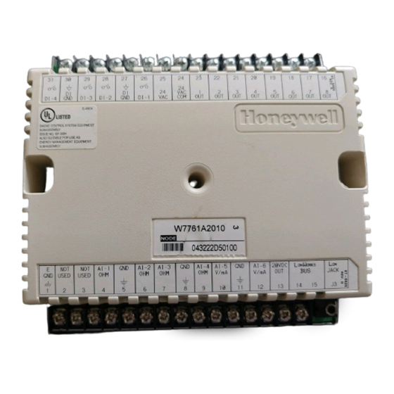
Fig. 3. Excel 10 W7761A Remote I/O Device. ................................................... 10
Fig. 4. W7761A construction.............................................................................. 11
logo are Registered
Device
CONTENTS
4
5
5
6
6
6
6
7
7
9
9
2
4
5
74-2699
Advertisement
Table of Contents

Related Manuals for Honeywell W7761A


Summary of Contents for Honeywell W7761A
-
Page 1: Table Of Contents
W7761A Controller Status LEDs ... 37 T7780 DDWM Bypass Pushbutton... 38 Fig. 1. Typical system overview..Fig. 2. Typical W7761A control application..Fig. 3. Excel 10 W7761A Remote I/O Device..10 Fig. 4. W7761A construction... 11 Device CONTENTS... - Page 2 Fig. 17. Typical Humidity and Enthalpy (4 to 20 mA) sensor wiring diagram..Fig. 18. Typical Window and Occupancy sensor wiring diagram..Fig. 19. Typical PWM Valve Actuator and miscellaneous fan control to W7761A.29 Fig. 20. Typical Pneumatic transducer to (Series 60 - Floating) W7761A...
-
Page 3: Introduction
INTRODUCTION Description of Devices The W7761A, Excel 10 Remote Input/Output device, provides auxiliary inputs and outputs for use with an Excel 10 Zone Manager and Excel 10 controllers over the Echelon tool. The W7761A device uses Echelon transceiver (FTT) for greater network installation flexibility. The Excel 10 RIO device can be combined with the Excel 10 Zone Manager (FTT), other Excel Controllers, and the Excel Building Supervisor, to provide a complete and low cost control solution for small to large commercial buildings. -
Page 4: Control Application
Excel 5000 controllers on the C-Bus through the Excel 10 Zone Manager. This would allow the controllers to use their physical inputs for monitoring other elements such as return humidity, IAQ, etc. to achieve better control. The W7761A can be used to average many space temperature sensors that are located in a zone that is controlled by the W7750 Constant Volume AHU Controller. -
Page 5: Product Names
74-2039 XBS User’s Manual 74-5018 XBS Application Guide Product Names The W7761A Remote I/O Device is available in one model: • W7761A Remote Input/Output Device. The T7770 Wall Module is available in five models: • T7770A1xxx Wall Module with temperature sensor only - not applicable to the RIO device (jumper switches the sensor from 20Kohm NTC to a linearized version of a 20 Kohm NTC used with the W7751A,C,E,G). -
Page 6: Agency Listings
CARE - Computer Aided Regulation Engineering; the PC based tool used to configure C-Bus and E-Bus devices. C-Bus -Honeywell proprietary Control Bus for communications between EXCEL 5000® System controllers and components. CPU - Central Processing Unit; an EXCEL 5000® System controller module. - Page 7 Level IV - Refers to a classification of digital communication wire. Formerly known as UL Level IV, but not equivalent to Category IV cable. If there is any question about wire compatibility, use Honeywell-approved cables (see Step 5 Order Equipment section).
-
Page 8: Construction
Controllers The Excel 10 W7761A RIO Device is available in one model. It contains 4 resistive inputs that can be configured for either 20Kohm NTC or PT3000 sensors, 2 voltage or current inputs, 4 digital inputs and 8 Digital Outputs (Triacs) which may be Discrete (maintained or momentary), Modulating (PWM) or Floating. - Page 9 O H M G N D A I - 4 O H M O H M Fig. 3. Excel 10 W7761A Remote I/O Device. EXCEL 10 W7761A INPUT/OUTPUT DEVICE W 7761A 2 1 2 0 19 1 8 O U T 2...
- Page 10 V / m A 11 1 2 5 -3 /1 6 (1 3 2 ) 6 (1 5 2 ) Fig. 4. W7761A construction in in. (mm). EXCEL 10 W7761A INPUT/OUTPUT DEVICE 2 -1 /8 (5 4 ) 1 9 1 8...
-
Page 11: Performance Specifications
Power: 24 Vac with a minimum of 20 Vac and a maximum of 30 Vac at either 50 or 60 Hz. The W7761A power consumption is 6 VA maximum at 50 or 60 Hz. The W7761A is a NEC Class 2 rated device. This listing imposes limits on the amount of power the product can consume or directly control to a total of 100 VA (U.S. - Page 12 55 to 85°F (13 to 29°C) when configured and connected to T7770 Wall Modules or T7780 DDWM. Communications: The W7761A Device uses a transformer-coupled communications port with differential Manchester-encoded data at 78 kilobits per second (kbs). The transformer-coupled communications interface offers a much higher degree of common-mode noise rejection while ensuring dc isolation.
- Page 13 Triac Outputs: Triac Outputs on the RIO: — Power ratings: 20 Vac to 30 Vac at 25 mA MIN to 500 mA MAX current for any voltage. EXCEL 10 W7761A INPUT/OUTPUT DEVICE sensors. sensors. 74-2699...
-
Page 14: Wall Modules
When any device is energized by a Triac, the device must be able to sink a minimum of 25 mA. NOTE: Triacs sink current to the 24 Vac common (COM terminal on the W7761A); see Fig. 19 for wiring example. -
Page 15: Configurations
Excel 10 controllers on the E-Bus or Excel 5000 controllers on the C-Bus through the Excel 10 Zone Manager. The W7761A can be used to monitor Occupancy, Window, Dirty filter, Indoor air quality, and Smoke control sensors. -
Page 16: Mixed-Output-Type Control
Dirty Filter Monitor The air filter in the air handler can be monitored by the W7761A RIO device and an alarm issued by the Zone Manager when the filter media needs replacement. The two methods of monitoring the filter are: 1. -
Page 17: Application Steps
Plan the use of the W7761A Devices according to the job requirements. Determine the location, functionality and sensor or actuator usage. Verify the sales estimate of the number of W7761A Devices and the number and type of output actuators and other required accessories. -
Page 18: Step 2. Determine Other Bus Devices Required
Step 2. Determine Other Bus Devices Required A maximum of 62 nodes can communicate on a single E-Bus segment. Each W7761A (RIO), W7750 (CVAHU), W7751 (VAV) Controller or T7780 Wall Module constitutes one node. If more nodes are required, a Q7751A Router is necessary. Using a router allows up to 125 nodes, divided between two E-Bus segments. - Page 19 EXCEL 10 W7761A INPUT/OUTPUT DEVICE NOTE: For wiring details see the E-Bus Termination Module subsection in Step 4. For wall module wiring, US part AK3782 (non-plenum) or US part AK3792 (plenum) can be used. These cables contain two twisted pairs (one for the run down to the wall module, and one for the run back up to the controller) for ease of installation.
-
Page 20: Power Wiring
Excel 10 W7761 Device. This includes the device itself, the equipment actuators (ML6161, or other motors) and various contactors and transducers, as appropriate, for the Excel 10 configuration. Power Budget Calculation Example The following is an example power budget calculation for a typical W7761A Excel 10 Device. Device Excel 10 W7761 6.0 VA... -
Page 21: Line Loss
Table 5 . VA Ratings For Transformer Sizing. 21.0 12.0 ) wire has a resistance of 2.57 ohms per 1000 ft which, ) wire is the recommended wire size for 24 Vac wiring. EXCEL 10 W7761A INPUT/OUTPUT DEVICE ) wire. 74-2699... - Page 22 With 100 percent load, the transformer secondary must supply between 23 and 25 volts to meet the NEMA standard. When a purchased transformer meets the NEMA standard DC20-1986, the transformer voltage-regulating ability can be considered reliable. Compliance with the NEMA standard is voluntary. The following Honeywell transformers meet this NEMA standard: Transformer Type AT20A...
- Page 23 Fig. 13. Power wiring details for two or more Excel 10s per transformer. IMPORTANT If the W7761A Device is used on Heating and Cooling Equipment (UL 1995 US only) devices and the transformer primary power is more than 150 volts, connect the transformer secondary to earth ground, see Fig. 14.
-
Page 24: Step 4. Prepare Wiring Diagrams
NOTE: If an Excel 10 W7761A Device or Zone Manager is not connected to a good earth ground, the device internal transient protection circuitry is compromised and the function of protecting the device from noise and power line spikes cannot be fulfilled. -
Page 25: Table 7. W7761A I/O Description
(10) STRIP 3/8 IN. (10 MM) FROM WIRES TO BE ATTACHED AT ONE TERMINAL. Fig. 15. Attaching two or more wires at terminal blocks. See Table 7 for a description of the W7761A terminals. Terminal Terminal Number OUT 8 Digital Output 8... - Page 26 Analog Input 1 resistance Not Used Not Used EGND Earth Ground See Fig. 20 to wire a pneumatic transducer to a W7761A. Fig. 16. Typical T7770A and C7770A wiring diagram. (For note 2, refer to Fig. 15.) C7770A AIR TEMPERATURE SENSOR 24 VAC...
- Page 27 TOG ETHER BEFO RE INS ERTI ON INTO THE TERMINAL B LOCK. Fig. 17. Typical Humidity and Enthalpy (4 to 20mA) sensor wiring diagram. (For note 2, refer to Fig. 15.) EXCEL 10 W7761A INPUT/OUTPUT DEVICE 24 VA C TRI AC EQUIV AL ENT CIRCUIT...
- Page 28 TO ASSURE PROPER ELECTRICAL CONTACT, WIRES MUST BE TWISTED TOGETHER BEFORE INSERTION INTO THE TERMINAL BLOCK. Fig. 18. Typical Window and Occupancy sensor wiring diagram. (For note 2, refer to Fig. 15.) EXCEL 10 W7761A INPUT/OUTPUT DEVICE 24 VAC TRIAC EQUIVALENT CIRCUIT E-BUS ), FOR EARTH GROUND WIRE.
- Page 29 TO ASSURE PROPER ELECTRICAL CONTACT, WIRES MUST BE TWISTED TOGETHER BEFORE INSERTION INTO THE TERMINAL BLOCK. Fig. 19. Typical PWM Valve Actuator and miscellaneous fan control to W7761A. (For note 2, refer to Fig. 15.) EXCEL 10 W7761A INPUT/OUTPUT DEVICE...
-
Page 30: E-Bus Termination Module
24 VAC Fig. 20. Typical Pneumatic transducer (Series 60 - Floating) to W7761A. E-Bus Termination Module One E-Bus Termination Module, part number 209541B is required for a single terminated E-Bus or two E-Bus Termination Module, part number 209541B for a double terminated E-Bus (see Fig. 21). Refer to the E-Bus Wiring Guidelines form, 74- 2865 for termination module placement rules. - Page 31 Fig. 21. Typical E-Bus termination module wiring diagrams (place a wire nut on each remaining wire that is not See Fig. 22 for E-Bus termination wiring options. W7753A 1415 1415 ORANGE PART NO. 209541B PART NO. 209541B TERMINATION TERMINATION MODULE MODULE connected to a controller or device). EXCEL 10 W7761A INPUT/OUTPUT DEVICE W7753A 1415 BROWN ORANGE M12690 74-2699...
- Page 32 EXCEL 10 W7761A INPUT/OUTPUT DEVICE Fig. 22. E-Bus termination wiring options. 74-2699...
-
Page 33: Step 5. Order Equipment
After compiling a bill of materials through completion of the previous application steps, refer to Table 8 for ordering information. Contact Honeywell for information about Controllers and Wall Modules with no logo. Table 8. Excel 10 W7761A Device Ordering Information. - Page 34 Table 8. Excel 10 W7761A Device Ordering Information (Continued). Part Number C7031J1050 Averaging Discharge/Return Air Temperature Sensor. 20 Kohm NTC C7031B1033 Discharge Air or Hot Water Temperature Sensor. 20 Kohm NTC C7031C1031 Duct Discharge/Return Air Sensor. 20 Kohm C7031D1062 Hot or chilled Water Temperature Sensor. 20 Kohm C7031K1017 Hot or chilled Water Temperature Sensor.
- Page 35 Table 8. Excel 10 W7761A Device Ordering Information (Continued). Part Number ML6474A1008 Direct Coupled Actuator, 132 lb-in. torque, Series 60 ML6185A1000 Direct Coupled Actuator, 50 lb-in. spring return EL7680A1008 Wall Mounted Wide View Infrared Occupancy Sensor EL7628A1007 Ceiling Mounted Infrared Occupancy Sensor...
-
Page 36: Step 6. Configure Devices
14 AWG (2.0 mm (typical or equivalent) Step 6. Configure Devices Excel E-Vision PC Software is used to configure W7761A Devices to match their intended application. The E-Vision User Guide form, 74-2588 provides details for operating the PC software. Step 7. Troubleshooting Troubleshooting Excel 10 Controllers and Wall Modules In addition to the following information, refer to the Installation Instructions and Checkout and Test manual for each product. -
Page 37: Broadcasting The Service Message
W7761A Device Status LED The LED on the front and center of a W7761A Device provides a visual indication of the status of the device. See Fig. 25. When the W7761A receives power, the LED should appear in one of the following allowable states (see Table 10): EXCEL 10 W7761A INPUT/OUTPUT DEVICE Table 9. -
Page 38: T7780 Ddwm Bypass Pushbutton
When the space is in Standby mode, the half-sun symbol is shown. When the space is in Unoccupied mode, the moon symbol is shown. Table 10. LED States. Hardware or Service LED Blink Rate (Cycles per second) steady ON or OFF W7750 STATUS Fig. 25. LED location on W7761A. EXCEL 10 W7761A INPUT/OUTPUT DEVICE M10095 74-2699... -
Page 39: Appendices
The resistive temperature sensors and voltage/current inputs can all be calibrated. The wall module setpoint potentiometer is not supported on the W7761A. Perform the sensor calibration by adding an offset value (either positive or negative) to the sensed value using E-Vision menus (see E-Vision user guide form, 74-2588). -
Page 40: Adding Other Voltage/Current Sensors
Custom Mapping function of E-Vision. The procedure described previously for adding an enthalpy ( 4 to 20 mA) sensor should be followed and instructs the user on adding the pseudo analog point in the RIO CARE Plant and using the EXCEL 10 W7761A INPUT/OUTPUT DEVICE 74-2699... -
Page 41: Adding Digital Inputs
3. Translate the Zone Manager and Export the Zone Manager files to E-Vision by selecting the Project and Export to E- Vision menu items. Type in the name of the Zone Manager Export file when the Export Zone Manager dialog box is EXCEL 10 W7761A INPUT/OUTPUT DEVICE RIO Network Variable that contains the... -
Page 42: Appendix B. Sequences Of Operation
The Excel 10 W7761A Device contains inputs and outputs, but no control software. All control that would be associated with the inputs and outputs in the W7761A would be accomplished though the Excel Zone Manager and would not be suitable for VAV control, temperature control, or any control function that would require less than a 30 second update rate. -
Page 43: Window Sensor (Statuswndw)
Dirty Filter Monitor The air filter in the air handler can be monitored by a digital input in the W7761A and an alarm issued by the Zone Manager when the filter media needs replacement. The two methods of monitoring the filter are: 1. -
Page 44: Appendix C. Complete List Of Excel 10 W7761A Remote I/O Device User Addresses
Pressure Tables C1 through C5 list all network variables associated with the W7761A Controller and the default User Address names. Table C1 lists the Network Variable Inputs and Outputs, which are stored in RAM memory. Table C2 lists the Control Parameters, which are the values stored in the controllers EEPROM memory. -
Page 45: Table C1.Input/Output Points
NvName AI1RType ncirioIoSelect AI2RType ncirioIoSelect AI3RType ncirioIoSelect AI4RType ncirioIoSelect AI5VType ncirioIoSelect AI6VType ncirioIoSelect EXCEL 10 W7761A INPUT/OUTPUT DEVICE Table C1. Input/Output Points (Left). Engineering Units: English (Metric) or Field Name States plus Range ResistiveIn0 DA_Temp_PT3000 OA_Temp_PT3000 RA_Temp_PT3000 Custom_PT3000 DA_Temp_20KNTC RA_Temp_20KNTC... - Page 46 AI5VType specifies which logical voltage or current sensor is assigned to which physical analog input sensor channel according to the enumerated list that is shown in the Eng. Units/States column. AI6VType: Refer to the description for AI5VType. EXCEL 10 W7761A INPUT/OUTPUT DEVICE Comments (continued) 74-2699...
- Page 47 -163 to 163 percent -163 to 163 percent -163 to 163 percent -163 to 163 DigitalIn0S1 Active_Short Active_Open Unused_DigInput DigitalIn1S1 See DI1Sel1Type Eng. Units/States column for selections. EXCEL 10 W7761A INPUT/OUTPUT DEVICE Digital State Value State Default Unused_DigInput Unused_DigInput (continued) 74-2699...
- Page 48 DI1Sel1Type specifies the sensor type and function connected to DigitalIn0S1 through DigitalIn3S1. The valid enumerated list of logical digital states for DigitalIn0S1 is listed in the Eng. Units/States column. DI2Sel1Type: Refer to the description for DI1Sel1Type. EXCEL 10 W7761A INPUT/OUTPUT DEVICE Comments (continued) 74-2699...
- Page 49 Modulate4 Modulate5 Modulate6 Modulate7 Modulate8 Float1_Open Float2_Open Float3_Open Float4_Open Float5_Open Float6_Open Float7_Open Float8_Open Float1_Close Float2_Close Float3_Close Float4_Close Float5_Close Float6_Close Float7_Close Float8_Close Unused_DigOutput EXCEL 10 W7761A INPUT/OUTPUT DEVICE Digital State Value State Default Unused_DigInput Unused_DigInput Maintained Maintained Maintained Maintained Unused_DigOutput 74-2699...
- Page 50 DI4Sel2Type: Refer to the description for DI1Sel2Type. DO1Type specifies which logical digital output function is assigned to the digital physical output according to the enumerated list that is shown in the Eng. Units/States column. EXCEL 10 W7761A INPUT/OUTPUT DEVICE Comments 74-2699...
- Page 51 FiftySixtyHz Sixty Fifty 0 to 65535 milliamps -20.0 to 200.0 DI1Value 0 to 255 DI1State ST_OFF ST_LOW ST_MED ST_HIGH ST_ON ST_NUL EXCEL 10 W7761A INPUT/OUTPUT DEVICE Digital State Value State Default Unused_DigOutput Unused_DigOutput Unused_DigOutput Unused_DigOutput Unused_DigOutput Unused_DigOutput Unused_DigOutput Sixty ST_NUL...
- Page 52 SNVT_switch. Refer to the enumerated list that is shown in the Eng. Units/States column. EXCEL 10 W7761A INPUT/OUTPUT DEVICE Comments (continued) 74-2699...
- Page 53 C (-40 to 116) degrees F -40 to 240 degrees C (-40 to 116) degrees F -40 to 240 degrees C (-40 to 116) Volts 0.0 to 10.5 EXCEL 10 W7761A INPUT/OUTPUT DEVICE Digital State Value State Default ST_NUL...
- Page 54 (AI4). This NV will contain AI4 temperature value with the OffsetCal1AI4 applied to it. SrcVoltageAI is an output network variable corresponding to the voltage or current input channel (AI5 or AI6) if the selection for a voltage sensor was made via ncirioIoSelect. EXCEL 10 W7761A INPUT/OUTPUT DEVICE Comments 74-2699...
-
Page 55: Table C2. Control Parameters
EXCEL 10 W7761A INPUT/OUTPUT DEVICE Table C2. Control Parameters (Left). Digital State Engineering Units: Value English (Metric) or User Address NvName Field Name States plus Range State Default nviInUse InUseNumber 0 to 65534 0xFFFF 74-2699... - Page 56 EXCEL 10 W7761A INPUT/OUTPUT DEVICE Table C2. Control Parameters (Right). Share (SH), Map (MA), Direct Access (DA) E-Vision (EV): Calibrate (C), Monitor (M), Parameter (P), Schematic (S) Hardware Configuration (HW), Manual Point (MN), Test (TS) Comments nviInUse is used by a management node to indicate to all other management nodes that it is logged on, to the Excel 10 node and that they should not try to interact with any of the Excel 10s network variables.
-
Page 57: Table C3. Status Points
Eng. Units/States column. Refer to the AlarmType enumerated list shown in the Eng. Units/States column. Refer to the AlarmType enumerated list shown in the Eng. Units/States column. FALSE TRUE EXCEL 10 W7761A INPUT/OUTPUT DEVICE Digital State Value State Default NO_ALARM NO_ALARM NO_ALARM... - Page 58 INPUT_NV_FAILURE alarm. nvoError tells which sensor(s) or network variable(s) have failed. See nvoAlarm, AlarmTypeLog for related subjects. EXCEL 10 W7761A INPUT/OUTPUT DEVICE Comments node number (in domain entry 1 of the nodes domain...
- Page 59 ElectricalFault FALSE TRUE FailSelfTest FALSE TRUE FeedbackFailure FALSE TRUE InAlarm FALSE TRUE InvalidId FALSE TRUE InvalidRequest FALSE TRUE EXCEL 10 W7761A INPUT/OUTPUT DEVICE Digital State Value State Default FALSE FALSE FALSE RIO1 FALSE FALSE FALSE FALSE FALSE FALSE FALSE FALSE...
- Page 60 InvalidId: If object_id is not a valid object, invalid_id is set to 1 (TRUE) otherwise it is set to 0 (FALSE). InvalidRequest: If object_request is not a valid request for the object addressed, InvalidRequest is set to 1 (TRUE) otherwise it is set to 0 (FALSE). EXCEL 10 W7761A INPUT/OUTPUT DEVICE Comments (continued) 74-2699...
- Page 61 OutOfService FALSE TRUE OverRange FALSE TRUE SelfTestInProgress FALSE TRUE UnableToMeasure FALSE TRUE UnderRange FALSE TRUE EXCEL 10 W7761A INPUT/OUTPUT DEVICE Digital State Engineering Units: Value English (Metric) or States plus Range State FALSE FALSE FALSE FALSE FALSE FALSE FALSE FALSE...
- Page 62 EXCEL 10 W7761A INPUT/OUTPUT DEVICE Table C3. Status Points (Right Continued). Share (SH), Map (MA), Direct Access (DA) E-Vision (EV): Calibrate (C), Monitor (M), Parameter (P), Schematic (S) Hardware Configuration (HW), Manual Point (MN), Test (TS) Comments InOverride: This field is not supported and is set to 0 (FALSE).
- Page 63 C (-40 to 116) OutputResLowS7 degrees F -40 to 240 degrees C (-40 to 116) ResHigh Ohms 10 to 150000 ResLow Ohms 10 to 150000 EXCEL 10 W7761A INPUT/OUTPUT DEVICE Digital State Value State Default ASCII Blanks (continued) 74-2699...
-
Page 64: Table C4. Configurations Parameters
20 Kohm NTC sensor was 11,520 ohms, 99.0 degrees F (37.2 degrees C), the value that would be entered for AIResLow would be 1152 (the resistance value divided by ten). EXCEL 10 W7761A INPUT/OUTPUT DEVICE Comments (continued) 74-2699... - Page 65 DeltaV nciDelta DO1FlSpeed nciFloatConfig DO2FlSpeed nciFloatConfig DO3FlSpeed nciFloatConfig DO4FlSpeed nciFloatConfig EXCEL 10 W7761A INPUT/OUTPUT DEVICE Engineering Units: English (Metric) or Field Name States plus Range UpperLimitS7 degrees F -40 to 240 degrees C (-40 to 116) deltacurrent 0 to 256...
- Page 66 DO4FlSpeed is how long it takes for the actuator motor to move one cycle of travel from closed to open. This value would be required if DO4Type were configured to either Float_Open or Float_Close. EXCEL 10 W7761A INPUT/OUTPUT DEVICE Comments (continued)
- Page 67 DO3.si_pnct_time seconds 0.0 to 3000 DO3.si_delta_time seconds 0.0 to 3000 DO4.si_period_pwm seconds 0.0 to 3000 DO4.si_pnct_time seconds 0.0 to 3000 DO4.si_delta_time seconds 0.0 to 3000 EXCEL 10 W7761A INPUT/OUTPUT DEVICE Digital State Value State 25.6 25.5 25.6 25.5 25.6 25.5 25.6...
- Page 68 DO4PWMZero: Refer to the description for DO1PWMPeriod. DO4PWMFull: Refer to the description for DO1PWMPeriod. DO5PWMPeriod: Refer to the description for DO1PWMPeriod. DO5PWMZero: Refer to the description for DO1PWMPeriod. DO5PWMFull: Refer to the description for DO1PWMPeriod. EXCEL 10 W7761A INPUT/OUTPUT DEVICE Comments (continued) 74-2699...
- Page 69 DO7PWMZero: Refer to the description for DO1PWMPeriod. DO7PWMFull: Refer to the description for DO1PWMPeriod. DO8PWMPeriod: Refer to the description for DO1PWMPeriod. DO8PWMZero: Refer to the description for DO1PWMPeriod. DO8PWMFull: Refer to the description for DO1PWMPeriod. EXCEL 10 W7761A INPUT/OUTPUT DEVICE Digital State Value State 25.6...
-
Page 70: Table C5. Direct Access And Special Points
AlarmTypeLog to no longer record alarms. If alarms are suppressed, UNSUPPRESS_ALARMS causes AlarmType and AlarmTypeLog to be returned to reporting alarms. See nvoAlarm for more details. All unspecified values are the same as MODE_ENABLE. EXCEL 10 W7761A INPUT/OUTPUT DEVICE Digital State Value... -
Page 71: Appendix D. Q7750A Excel 10 Zone Manager Point Estimating Guide
30 = average. 45 = many points with read/write ability. (ADD ROUTER) NUMBER OF EXCEL 10s Fig. D-1. Point capacity estimate for Zone Manager. EXCEL 10 W7761A INPUT/OUTPUT DEVICE NUMBER OF C-BUS POINTS (EXCEL 10 MAPPED POINTS... -
Page 72: Appendix E. Sensor Data For Calibration
Table E-1. Sensor Resistance Versus Temperature. 2916.08 2964.68 3013.28 3061.88 3110.48 3159.08 3207.68 3256.28 3304.88 3353.48 3402.08 3450.68 3499.28 3547.88 3596.48 3645.08 3693.68 60 70 80 90 100 110 120 21.1 32.2 43.4 15.6 26.7 37.8 M11959 EXCEL 10 W7761A INPUT/OUTPUT DEVICE 74-2699... - Page 73 60 65 70 75 80 85 90 95 100 105 110 115 120 12.8 18.3 23.9 29.4 -1.1 15.6 21.1 26.7 Table E-3 Sensor Resistance Versus Temperature. EXCEL 10 W7761A INPUT/OUTPUT DEVICE 40.6 46.1 32.2 37.8 43.3 48.9 M11960 74-2699...
-
Page 74: Voltage/Current Sensors
Table E-4 lists the points for Sensor Voltage versus Humidity. Fig. E-4 shows the graph of these points. Humidity Percentage Sensor Voltage 20K OHM AT TEMPERATURE (DEGREES) Table E-4. Sensor Voltage Versus Humidity. 2.67 3.08 3.48 3.88 4.28 4.68 5.08 5.48 5.88 6.28 6.69 7.09 7.49 7.89 8.29 EXCEL 10 W7761A INPUT/OUTPUT DEVICE F (25 M5874A 74-2699... - Page 75 40 45 50 55 PERCENTAGE Fig. E-4. Graph of Sensor Voltage versus Humidity. Table E-5. Sensor Current Versus Humidity. 10.4 11.2 12.0 12.8 13.6 14.4 15.2 16.0 16.8 17.6 18.4 EXCEL 10 W7761A INPUT/OUTPUT DEVICE 80 85 90 M11610 74-2699...
- Page 76 4.50 4.25 4.00 3.75 3.50 3.25 3.00 2.75 2.50 2.25 2.00 1.75 1.50 1.25 1.00 11 12 13 14 (MA) EXCEL 10 W7761A INPUT/OUTPUT DEVICE RH (%) I (mA) 10.4 12.0 13.6 15.2 16.8 18.4 M3131B 19 20 M11607 74-2699...
- Page 77 (16) (18) (21) APPROXIMATE DRY BULB TEMPERATURE— F ( C) C7400A OUTPUT CURRENT D C B (10) (16) (21) (27) TEMPERATURE F ( C) EXCEL 10 W7761A INPUT/OUTPUT DEVICE (29) (32) (35) (38) (41) (43) (27) (24) (27) (29) (32)
- Page 78 3.00 3.50 4.00 4.50 5.00 5.50 6.00 6.50 7.00 7.50 8.00 8.50 9.00 9.50 10.00 SENSOR VOLTAGE VERSUS CO2 CONCENTRATION 1100 1300 1000 1200 EXCEL 10 W7761A INPUT/OUTPUT DEVICE Concentration. 1500 1700 1900 1400 1600 1800 2000 M11611 concentration. 74-2699...
- Page 79 3.25 3.50 3.75 4.00 4.25 4.50 4.75 5.00 SENSOR VOLTAGE VERSUS INPUT VOLTAGE TO A/D 5.00 4.50 4.00 3.50 3.00 2.50 2.00 1.50 1.00 0.50 VOLTS 2.00 2.80 3.60 4.40 5.20 6.00 EXCEL 10 W7761A INPUT/OUTPUT DEVICE 1000 M11612 74-2699...
- Page 80 SENSOR VOLTAGE VERSUS PRESSURE 0.50 1.00 1.50 2.00 2.50 3.00 3.50 0.13 0.25 0.37 0.62 0.75 0.87 +RPH DQG %XLOGLQJ &RQWURO 3URGXFWV Printed in U.S.A. on recycled paper containing at least 10% post-consumer paper fibers. 4.00 4.50 5.00 1.12 1.25 M11963 www.honeywell.com...