Yamaha Portatone PSR A1000 Service Manual
Hide thumbs
Also See for Portatone PSR A1000:
- Owner's manual (13 pages) ,
- Service manual (22 pages) ,
- Quick start manual (32 pages)
Table of Contents
Advertisement
Quick Links
SERVICE MANUAL
CONTENTS
SPECIFICATIONS ··································································· 2
PANEL LAYOUT ······································································· 4
CIRCUIT BOARD LAYOUT & WIRING ···································· 6
DISASSEMBLY PROCEDURE ················································ 8
LSI PIN DESCRIPTION ························································· 12
IC BLOCK DIAGRAM ···························································· 16
CIRCUIT BOARDS ································································ 17
TEST PROGRAM ·································································· 33
SYSTEM RESET ··································································· 36
MIDI IMPLEMENTATION CHART ·········································· 37
MIDI DATA FORMAT ······························································ 38
PARTS LIST
BLOCK DIAGRAM
OVERALL CIRCUIT DIAGRAM
This document is printed on chlorine free (ECF) paper.
PK
001683
HAMAMATSU, JAPAN
Copyright (c) Yamaha Corporation. All rights reserved. PDF-K5531
'02.08
Advertisement
Chapters
Table of Contents

Related Manuals for Yamaha Portatone PSR A1000


Summary of Contents for Yamaha Portatone PSR A1000
- Page 1 SYSTEM RESET ··································································· 36 MIDI IMPLEMENTATION CHART ·········································· 37 MIDI DATA FORMAT ······························································ 38 PARTS LIST BLOCK DIAGRAM OVERALL CIRCUIT DIAGRAM This document is printed on chlorine free (ECF) paper. 001683 HAMAMATSU, JAPAN Copyright (c) Yamaha Corporation. All rights reserved. PDF-K5531 '02.08...
-
Page 2: Specifications
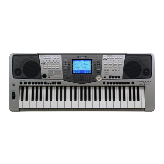
IMPORTANT NOTICE This manual has been provided for the use of authorized Yamaha Retailers and their service personnel. It has been assumed that basic service procedures inherent to the industry, and more specifically Yamaha Products, are already known and understood by the users, and have therefore not been restated. - Page 3 Speakers (12 cm + 5 cm) x 2 Power Consumption 31 W Power supply Yamaha AC adaptor PA-300 (included) * Dimensions [W x D x H] 973 x 399 x 161 mm (without Music Stand) [38-5/16" x 15-11/16" x 6-5/16"] Weight 10.0 Kg (22 lbs., 1 oz)
-
Page 4: Panel Layout
PSR-A1000 PANEL LAYOUT 10 11 12 20 21 22 23 24 25 26 27 28 29 30 [AUTO FILL IN] button POWER STYLE [STANDBY/ON] switch STYLE buttons [FADE IN / OUT] button [SYNC.STOP] button WHEEL SCALE SETTING PITCH BEND [SCALE SETTING] buttons [SYNC.START] button [START / STOP] button PHONES... - Page 5 PSR-A1000 52 53 54 55 56 57 58 ] - [8 ] buttons VOICE FLOPPY DISK [BACK] button VOICE buttons Floppy disk drive (3.5”) [NEXT] button TRANSPOSE Connectors VOICE PART ON / OFF [MAIN] button ] buttons [TO HOST] terminal VOICE PART ON / OFF [LAYER] button [HOST SELECT] switch TEMPO...
-
Page 6: Circuit Board Layout & Wiring
PSR-A1000 CIRCUIT BOARD LAYOUT & WIRING Lower case assembly L160 L110 L170 Speaker L (Woofer) Speaker R (Woofer) U380 U390 Upper case assembly WH008 WH003 WH007 U420 WH002 WH007 MKS5F Keyboard assembly WH005 WH006 Speaker R (Tweeter) MK-H MK-L Speaker L (Tweeter) U380 U390 U420... - Page 7 PSR-A1000 Location Part No. Connector Assembly Destination Remarks (V778240) MKS5F-CN1 DM-CN102 (V778260) Speaker (Tweeter) AM-CN109 4P L=800 mm (V778270) INVP INV-CN1 DM-CN104 2P L=200 mm (V778280) INV-CN2 LCD (Backlight) 4P L=100 mm (V815810) AM-CN103 DM-CN908 L110 (V778250) Speaker (Woofer) AM-CN110 5P L=800 mm L160 V7782900...
-
Page 8: Disassembly Procedure
PSR-A1000 DISASSEMBLY PROCEDURE Caution: Be sure to attach the removed filament tape just as it was before removal. Lower Case Assembly [240] Lower case assembly [240] (Time required: About 5 minutes) Remove the sixteen (16) screws marked [240] and the two (2) screws marked [250A]. - Page 9 PSR-A1000 SW Circuit Board AM Circuit Board (Time required: About 10 minutes) (Time required: About 15 minutes) Remove the lower case assembly. (See procedure 1.) Remove the lower case assembly. (See procedure 1.) Remove the two (2) screws marked [340]. The SW circuit Remove the INV circuit board.
- Page 10 PSR-A1000 VR, ENC, PN1, PN2, PN3, PN4 Circuit 12-7 PN1 Circuit Board Boards and LCD (Time required: About 25 minutes) : 12-1 Remove the lower case assembly. (See procedure 1.) 12-7-1 Remove the keyboard assembly. (See procedure 8.) 12-2 Remove the INV circuit board. (See procedure 5.) 12-7-2 Remove the two (2) screws marked [520B].
- Page 11 PSR-A1000 12-10 PN4 Circuit board (Time required: About 20 minutes) : 12-10-1 Remove the five (5) screws marked [520I]. The PN4 cir- [510] cuit board can then be removed. (Fig. 7) LCD holder 12-11 LCD (Time required: About 20 minutes) : 12-11-1 Remove the four (4) screws marked [520J].
-
Page 12: Lsi Pin Description
PSR-A1000 LSI PIN DESCRIPTION HD63266F (XI939A00) FDC ··············································································································· 12 PD789022GB-A15-8E (XZ560100) CPU KBS ················································································· 12 HD6417709F80B (XV250B00) CPU ··································································································· 13 HG73C205AFD (XU947C00) SWX00B ······························································································ 14 S1D13305F00B100 (XQ595A00) LCDC ···························································································· 15 AD1854JRSRL (XY782A00) DAC ······································································································ 15 HD63266F (XI939A00) FDC (Floppy Disk Controller) DM: IC300 NAME FUNCTION... - Page 13 PSR-A1000 HD6417709F80B (XV250B00) CPU DM: IC100 NAME FUNCTION NAME FUNCTION CKE/PTK[5] CK enable (SDRAM)/ I/O port K System clock RAS3L/PTJ[0] RAS/ I/O port J Vcc (RTC) Power supply (3.3 V) RAS2L/PTJ[1] RAS/ I/O port J XTAL2 Clock CASLL/CAS/PTJ[2] CAS (DRAM)/CAS (SDRAM)/ I/O port J EXTAL2 Clock Ground (0 V)
- Page 14 PSR-A1000 HG73C205AFD (XU947C00) SWX00B (Tone Generator) DM: IC801 NAME FUNCTION NAME FUNCTION Initial clear CMA3 Program address bus Program address bus RFCLKI PLL Clock CMA8 PLL Control CMA2 Program address bus AVDD_PLL Power supply read signal AVSS_PLL Ground CMA1 Program address bus MODE0 SWX dual mode high byte effective signal...
- Page 15 PSR-A1000 S1D13305F00B100 (XQ595A00) LCDC (LCD Controller) DM: IC500 NAME FUNCTION NAME FUNCTION Data bus output for 4 bit dot VRAM address bus XECL S driver enable, chain clock XSCL Data bus shift clock Ground /VWR VRAM read/write X driver latch pulse /VCE Memory control Frame signal for X/Y driver...
-
Page 16: Ic Block Diagram
PSR-A1000 IC BLOCK DIAGRAM SN74HCU04NSR (XW842A00) HD74LV08AFPEL (IS000800) HD74LV21ATELL (X0010A00) SN74HCU04N (IG142250) Quad 2 Input AND Dual 4 Input AND Hex Inverter DM: IC101 DM: IC310 IC510, 511 IC301 SN74HC132NSR (XW792A00) SN74HCT138NSR (XY865A00) HD74LVC139FPEL (XS048A00) MM74HC132SJX (XY352A00) 3 to 8 Demultiplexer Dual 2 to 4 Demultiplexer Quad 2 Input NAND DM: IC600... -
Page 17: Table Of Contents
PSR-A1000 M5227P (XF751A00) µPC4570HA (XB247A00) µPC4570G2 (XF291A00) 5-Band Graphic Equalizer Dual Operational Amplifier Dual Operational Amplifier AM: IC104, 105 AM: IC100, 102, 107, 108, 111, 112 DM: 702, 703 +DC Voltage -Vcc Output A Supply Inverting Output B Input A Inverting Non-Inverting Input B... -
Page 18: Circuit Boards Contents
PSR-A1000 CIRCUIT BOARDS DM Circuit Board to PN1-CN2 to PN1-CN1 to AM-CN106 to AM-CN303 to LCD to AM-CN300 to AM-CN103 Component side 2NA-V763770-1... - Page 19 PSR-A1000 DM Circuit Board Pattern side 2NA-V763770-2...
- Page 20 PSR-A1000 PN1 Circuit Board MEMORY REGISTRATION MEMORY PN2 Circuit Board MULTI PAD DIRECT ACCESS STOP CHANNEL ON/OFF BALANCE (DOWN) (UP) TAP TEMPO TEMPO + TEMPO - (DOWN) (UP) USER PERCUSSION (DOWN) (UP) (DOWN) (UP) SYNTH. CHOIR & PAD STRI (DOWN) (UP) ORGA TRAMPET...
- Page 21 PSR-A1000 ENC Circuit Board to PN1-CN4 FREEZE DATA ENTRY ENTER Component side UPPER UPPER SCALE OCTAVE + OCTAVE - TUNING TRANSPOSE + TRANSPOSE - select J select I LEFT select H LAYER select G STRINGS SAX & FLUTE select F MAIN ORGAN &...
- Page 22 PSR-A1000 ENC Circuit Board PN1 Circuit Board to PN2-CN7 Pattern side to ENC-CN13 to DM-CN600 to PN3-CN8 to DM-CN100 PN1, ENC: 2NA-V922220...
- Page 23 PSR-A1000 PN2 Circuit Board Pattern side Pattern side PN1, PN2: 2NA-V922220...
- Page 24 PSR-A1000 PN4 Circuit Board EXTRA TRACKS TRACK 2 TRACK 1 REPEAT METRONOME START/STOP SONG Component side PN3 Circuit Board STYLE CONTROL MAIN ACMP BREAK INTRO PB1 Circuit Board PITCH BEND to PN3-CN10 Component side PN3, PN4, PB1: 2NA-V922230...
- Page 25 PSR-A1000 SOUND CREATOR select A DIGITAL RECORDING select B select C MIXING POP & ROCK LATIN & JAZZ DANCE & BALLROOM CONSOLE select D USER select E STYLE SCALE SETTING DEMO HELP FUNCTION SCALE MEMORY MEMORIZE ENDING/rit. SYNC. STOP SYNC. START START/STOP AUTO FADE...
- Page 26 PSR-A1000 PN3 Circuit Board to PN1-CN3 2NA-V922230...
- Page 27 PSR-A1000 PN4 Circuit Board Pattern side to PB1-CN16 Pattern side PB1 Circuit Board Pattern side PN3, PN4, PB1: 2NA-V922230...
- Page 28 PSR-A1000 AM Circuit Board CONTRAST HOST SELECT MIDI PC1 PC2 MIDI TO HOST to DM-CN501 to DM-CN908 to DM-CN105 Component side to DM-CN109 VR Circuit Board MASTER VOLUME Component side AM, VR: 2NA-V756840...
- Page 29 PSR-A1000 FOOT PEDAL AUX OUT (LEVEL FIXED) (SWITCH) to Speakers to Speakers : not installed (Woofer) (Tweeter) INV Circuit Board to LCD (Backlight) to DM-CN104 AM: 2NA-V756840 Component side INV: 2NA-V420050...
- Page 30 PSR-A1000 OUT PUT L/L+R DC-IN 16V SW Circuit Board STANDBY/ON Component side HP Circuit Board PHONES Component side Component side AM, HP, SW: 2NA-V756840...
- Page 31 PSR-A1000 MK-L Circuit Board to MK-H Component side MKS5F Circuit Board to MK-H to DM-CN102 Component side MK-L: 2NA-VV58380 MKS5F: 2NAKZ-V814260...
- Page 32 PSR-A1000 MK-H Circuit Board to MKS5F-CN4 to MK-L Component side 2NA-VV583900...
-
Page 33: Test Program
PSR-A1000 TEST PROGRAM 1. Preparation 1) PA-300 (AC adaptor) is used. 2) The volume is usually moved to the use position when no volume change is required. 3) Measuring instruments: frequency counter, level meter (with JIS-C filter) Note: Connect a stereo plug to the [PHONES] jack at 33 ohms. 4) Jigs: foot switch (FC-4), foot volume (FC-7), MIDI cable, floppy disk (2HD &... - Page 34 PSR-A1000 LCD (initial) Test Function and Judgment criteria 017: Output L Check Connect the level meter (with a JIS-C filter) to each terminal (PHONES, OUTPUT L/L+R, R, AUX OUT L, R). Set the [MASTER VOLUME] at MAX and check the L channel output level. (1 kHz sine wave, PAN=L) (PHONES L, R: 33 ohm load OUTPUT L/L+R, R: 10 kohm load AUX OUT L, R: 10 kohm load)
- Page 35 PSR-A1000 • Power On Reset Set to the factory preset data when the [STANDBY/ON] switch is turned on while pressing the highest (rightmost) white key on the keyboard. • TABLE 1 ORDER SWITCH NOTE ORDER SWITCH NOTE EXTRA TRACKS TRACK2 TRACK1 REPEAT METRONOME...
-
Page 36: System Reset
PSR-A1000 SYSTEM RESET This operation lets you restore the PSR-A1000 to its original factory settings. These settings include System Setup, MIDI Setup, User Effect, and Files & Folders. Restores the System Setup parameters to the original factory settings. You can also restore only the System Setup settings by simultaneously holding down the highest key on the keyboard (C6) The functions and settings... -
Page 37: Midi Implementation Chart
PSR-A1000 MIDI IMPLEMENTATION CHART YAMAHA [ Portable Keyboard ] Date : 29,March 2002 Model PSR-A1000 MIDI Implementation Chart Version : 1.00 Function... Transmitted Recognized Remarks Basic Default 1 - 16 1 - 16 Channel Changed 1 - 16 1 - 16... -
Page 38: Midi Data Format
PSR–A1000 MIDI DATA FORMAT Many MIDI messages listed in the MIDI Data Format are expressed in decimal numbers, binary numbers and hexadecimal numbers. Hexadecimal numbers may include the letter “H” as a suffix. Also, “n” can freely be defined as any whole number. To enter data/values, refer to the table below. - Page 39 PSR–A1000 MIDI CHANNEL MESSAGE (1) O: available MIDI Events Status byte 1st Data byte 2nd Data byte Corresponding Voice MIDI Reception (respond/ignore) MIDI Transmission (generated data) Main Panel Upper Status Data (HEX) Parameter Data (HEX) Parameter Regular Voice Song Layer Keyboard Style Extra M.Pad Style Song MIDI...
- Page 40 PSR–A1000 MIDI CHANNEL MESSAGE (2) NRPN NRPN Data Entry Corresponding Voice MIDI Reception (respond/ignore) MIDI Transmission (generated data) Main Parameter Data Range Panel Upper Regular Voice Song Layer Keyboard Style Extra M.Pad Style Song MIDI (main generation method) Lower Left –...
- Page 41 PSR–A1000 MIDI PARAMETER CHANGE TABLE * Not Received when Receive System Exclusive Message Parameters is set to off. * Not transmitted when Transmit System Exclusive Message Parmeters is set to on. MIDI Parameter Change table (XG SYSTEM) Corresponding Voice MIDI Reception (effective or not for each part) MIDI Transmission (generated data) Address Size...
- Page 42 PSR–A1000 Corresponding Voice MIDI Reception (effective or not for each part) MIDI Transmission (generated data) Address Size Data XG Default Main Parameter Description Panel Regular Voice Song Layer Keyboard Style Extra M.Pad Style Song MIDI (main generation method) Left 00-7F CHORUS TYPE MSB Refer to Effect Parameter 41(=CHORUS1)
- Page 43 PSR–A1000 Corresponding Voice MIDI Reception (effective or not for each part) MIDI Transmission (generated data) Address Size Data XG Default Main Parameter Description Panel Regular Voice Song Layer Keyboard Style Extra M.Pad Style Song MIDI (main generation method) Left 00-7F VARIATION PARAMETER Refer to Effect Parameter Depends on...
-
Page 44: Vss1
PSR–A1000 Corresponding Voice MIDI Reception (effective or not for each part) MIDI Transmission (generated data) Address Size Data XG Default Main Parameter Description Panel Regular Voice Song Layer Keyboard Style Extra M.Pad Style Song MIDI (main generation method) Left 00-01 Rcv PITCH BEND OFF, ON 00-01... - Page 45 PSR–A1000 Corresponding Voice MIDI Reception (effective or not for each part) MIDI Transmission (generated data) Address Size Data XG Default Main Parameter Description Panel Regular Voice Song Layer Keyboard Style Extra M.Pad Style Song MIDI (main generation method) Left NOT USED –...
-
Page 46: System Exclusive Messages
– – – – – O (Section LED) O (Section Sw) Control F0= Exclusive status 11110000 43= YAMAHA ID 01000011 7E= Style 01111110 00000000 ss= Switch No. 0sssssss 00H INTRO A 01H INTRO B 02H INTRO C 03H INTRO D... - Page 47 – * Refer to Parameter Change Table Parameter F0= Exclusive status eter Change Table (When 11110000 Change 01000011 43= YAMAHA ID receiving 0001nnnn 1n= Device Number n=always 0 (when transmit), the XG n=0-F (when recieve) Param- 01001100 4C= Model ID...
- Page 48 F0 43 1n 27 30 00 00 mm ll cc F7 O (Function) Master F0= Exclusive status 11110000 Tuning 01000011 43= YAMAHA ID 0001nnnn 1nn= always 0 (when transmit), n=0-F (when receive) 00100111 27= Model ID of TG100 00110000 30= Address High...
-
Page 49: Parts List
PARTS LIST CONTENTS OVERALL ASSEMBLY ··························································································································· 2 LOWER CASE ASSEMBLY ···················································································································· 4 UPPER CASE ASSEMBLY ···················································································································· 6 KEYBOARD ASSEMBLY ························································································································ 9 ELECTRICAL PARTS ····················································································································· 10~24 Notes: DESTINATION ABBREVIATIONS Australian model M: South African model British model O: Chinese model Canadian model Q: South-east Asia model German model Taiwan model... -
Page 50: Overall Assembly
PSR-A1000 OVERALL ASSEMBLY • AC Adapter (PA-300E) Upper case assembly (See page 6.) Keyboard assembly (See page 9.) Lower case assembly (See page 4.) -
Page 51: Am (X0189D0)
PSR-A1000 PART NO. DESCRIPTION REMARKS REF NO. QTY RANK OVERALL ASSEMBLY PSR-A1000 (V910700) Upper Case Assembly (V912870) V7632100 Keyboard Assembly 16M C61 P2M MKS5 Lower Case Assembly (V912890) XV910A00 Speaker 5.0cm 4ohm TWEETER Shield Cover U (V765410) Shield Cover L (V765430) Cushion 35X25XT1... -
Page 52: Lower Case Assembly
PSR-A1000 LOWER CASE ASSEMBLY Lower case sub assembly L100 L100 L100 L110 L120 Floppy disk drive assembly... - Page 53 PSR-A1000 PART NO. DESCRIPTION REMARKS REF NO. QTY RANK LOWER CASE ASSEMBLY PSR-A1000 (V912890) V9198100 Lower Case Sub Assembly Floppy Disk Drive Assembly (V766070) V7632700 Cover, FDD EP600280 Bind Head Tapping Screw-P 3.0X8 MFZN2Y VM839600 Bind Head Tapping Screw-P 4.0X16 MFZN2Y VA126100 Adhesive Tape 12X50...
-
Page 54: Upper Case Assembly
PSR-A1000 UPPER CASE ASSEMBLY Speaker grille L assembly U30a U30c 420a U30d U30c U30b U30d U30c Speaker grille R assembly 310b U40c U40d U40c U40b U40c U40a 310a U40d 310 500 Wheel assembly Upper case sub-assembly Contents of used LED lenz list Parts number Shape expansion figure V7479900 V7480000... - Page 55 PSR-A1000 PART NO. DESCRIPTION REMARKS REF NO. QTY RANK UPPER CASE ASSEMBLY PSR-A1000 (V912870) V9132400 Upper Case Sub-assembly Vibration-proof Sheet (V776010) Vibration-proof Sheet (V913250) Vibration-proof Sheet (V776030) Vibration-proof Sheet (V776040) Vibration-proof Sheet (V776050) Vibration-proof Sheet (V776060) Vibration-proof Sheet (V913260) Vibration-proof Sheet (V776080) V7656700 Panel Button Black...
- Page 56 U40b Nonwoven Fabric Cloth 55X8X0.5 (V766030) U40c Nonwoven Fabric Cloth 14X8X0.5 (V766040) U40d Nonwoven Fabric Cloth 40X8X0.5 (V826450) V7660600 Emblem YAMAHA EP600280 Bind Head Tapping Screw-P 3.0X8 MFZN2Y Spacer L=100 (V384790) Spacer L=20 (V834710) Spacer L=13 (V834720) : New Parts...
-
Page 57: Mk-H (Xr565B0)
PSR-A1000 KEYBOARD ASSEMBLY PART NO. DESCRIPTION REMARKS REF NO. QTY RANK V7632100 KEYBOARD ASSEMBLY 16M C61 P2M MKS5 PSR-A1000 EP630220 Bind Head Tapping Screw-P 3.0X8 MFZN2BL Frame C61 16M (VS15380) VU328600 Frame C61 16M VH1809C0 White Key 16L CEGBDFA VH180900 White Key 16L CEGB VH181000... -
Page 58: Electrical Parts
PSR-A1000 ELECTRICAL PARTS PART NO. DESCRIPTION REMARKS REF NO. QTY RANK ELECTRICAL PARTS PSR-A1000 V7749400 Circuit Board (V756880)(X0189D0) V7749600 Circuit Board (V756880)(X0189D0) V7749500 Circuit Board (V756880)(X0189D0) V7749700 Circuit Board (V756880)(X0189D0) V9222100 Circuit Board (X0128D0) V9239000 Circuit Board (V922220)(X2616B0) V9238800 Circuit Board (V922220)(X2616B0) V9238900 Circuit Board... - Page 59 PSR-A1000 PART NO. DESCRIPTION REMARKS REF NO. QTY RANK C0159 UA653470 Mylar Capacitor 4700P 50V J C0160 UA653820 Mylar Capacitor 8200P 50V J C0161 UA653820 Mylar Capacitor 8200P 50V J C0162 UA653470 Mylar Capacitor 4700P 50V J -0165 UA653470 Mylar Capacitor 4700P 50V J C0166 UR866220...
- Page 60 PSR-A1000 PART NO. DESCRIPTION REMARKS REF NO. QTY RANK CN103 VB390500 Connector Base Post PH 9P TE CN104 VI878400 Cable Holder 51048 6P TE CN105 VI878400 Cable Holder 51048 6P TE CN106 VI878300 Cable Holder 51048 5P TE CN108 VI878300 Cable Holder 51048 5P TE CN109...
- Page 61 PSR-A1000 PART NO. DESCRIPTION REMARKS REF NO. QTY RANK L0400 VB835000 Coil FL5R200QNT 20uH L0400 V2993400 Choke Coil R-5C.20U 20uH L0401 VB835000 Coil FL5R200QNT 20uH L0401 V2993400 Choke Coil R-5C.20U 20uH R0101 HF756470 Carbon Resistor 4.7K 1/4 J R0102 HF756470 Carbon Resistor 4.7K 1/4 J R0103...
- Page 62 PSR-A1000 PART NO. DESCRIPTION REMARKS REF NO. QTY RANK R0196 HF757220 Carbon Resistor 22.0K 1/4 J R0197 HF753220 Carbon Resistor 2.2 1/4 J R0198 HF757220 Carbon Resistor 22.0K 1/4 J R0199 HF753220 Carbon Resistor 2.2 1/4 J R0200 HF756470 Carbon Resistor 4.7K 1/4 J -0203 HF756470...
- Page 63 PSR-A1000 PART NO. DESCRIPTION REMARKS REF NO. QTY RANK C0001 US064100 Ceramic Capacitor-B (chip) 0.0100 50V K C0002 UR839100 Electrolytic Cap. 1000 16.0V C0005 US064100 Ceramic Capacitor-B (chip) 0.0100 50V K C0006 US062470 Ceramic Capacitor-SL(chip) 470P 50V J C0007 UF047100 Electrolytic Cap.
- Page 64 PSR-A1000 PART NO. DESCRIPTION REMARKS REF NO. QTY RANK C0304 US062470 Ceramic Capacitor-SL(chip) 470P 50V J C0305 US064100 Ceramic Capacitor-B (chip) 0.0100 50V K C0306 US062470 Ceramic Capacitor-SL(chip) 470P 50V J C0307 US064100 Ceramic Capacitor-B (chip) 0.0100 50V K C0308 US062470 Ceramic Capacitor-SL(chip) 470P 50V J...
- Page 65 PSR-A1000 PART NO. DESCRIPTION REMARKS REF NO. QTY RANK C0725 US062330 Ceramic Capacitor-SL(chip) 330P 50V J C0726 US135100 Ceramic Capacitor-F (chip) 0.1000 16V Z C0727 US062220 Ceramic Capacitor-SL(chip) 220P 50V J C0728 US062220 Ceramic Capacitor-SL(chip) 220P 50V J C0729 US135100 Ceramic Capacitor-F (chip) 0.1000 16V Z C0730...
- Page 66 PSR-A1000 PART NO. DESCRIPTION REMARKS REF NO. QTY RANK IC500 XQ595A00 S1D13305F00B100 LCDC IC501 XR115A00 UPD43256BGU-70L SRAM 256K IC501 XV411A00 W24258S-70LE-EL10 IC501 XW433A00 CY62256LL-70SNCT IC501 XZ388A00 W24257S-70LL-EL10 IC510 XW842A00 SN74HCU04NSR INVERTER IC511 XW842A00 SN74HCU04NSR INVERTER IC600 XY865A00 SN74HCT138NSR DECODER IC601 VT943400 Transistor Array TD62785F(TP1)
- Page 67 PSR-A1000 PART NO. DESCRIPTION REMARKS REF NO. QTY RANK R0098 RD355100 Carbon Resistor (chip) 100.0 63M J R0099 RD356150 Carbon Resistor (chip) 1.5K 63M J R0100 RD357100 Carbon Resistor (chip) 10.0K 63M J R0101 RD357100 Carbon Resistor (chip) 10.0K 63M J R0102 RD354680 Carbon Resistor (chip)
- Page 68 PSR-A1000 PART NO. DESCRIPTION REMARKS REF NO. QTY RANK R0729 RD354100 Carbon Resistor (chip) 10.0 63M J R0803 RD355220 Carbon Resistor (chip) 220.0 63M J R0804 RD357100 Carbon Resistor (chip) 10.0K 63M J R0805 RD355220 Carbon Resistor (chip) 220.0 63M J R0806 RD355220 Carbon Resistor (chip)
- Page 69 PSR-A1000 PART NO. DESCRIPTION REMARKS REF NO. QTY RANK LD128 VD180000 LED Red SLZ-190B-03 VOICE(STRINGS) LD129 VD180000 LED Red SLZ-190B-03 VOICE(CHOIR & PAD) LD130 VD180000 LED Red SLZ-190B-03 VOICE(SYNTH.) LD135 VT425100 LED Red SLZ-190B-17-T1 VOICE(XG) LD136 VT425100 LED Red SLZ-190B-17-T1 VOICE LD137 VT425100...
-
Page 70: Mks5F (X2002A0)
PSR-A1000 PART NO. DESCRIPTION REMARKS REF NO. QTY RANK SW106 VV056000 Tact Switch SKQNAED010 ENTER SW107 VV056000 Tact Switch SKQNAED010 MULTI PAD 1 SW108 VV056000 Tact Switch SKQNAED010 MULTI PAD 2 SW109 VV056000 Tact Switch SKQNAED010 MULTI PAD 3 SW110 VV056000 Tact Switch SKQNAED010... - Page 71 PSR-A1000 PART NO. DESCRIPTION REMARKS REF NO. QTY RANK CN009 V2426700 Connector, FFC 52207 11P SE CN010 VK024700 Wire Trap 52147 3P TE CN012 V2426700 Connector, FFC 52207 11P SE CN016 VI878100 Cable Holder 51048 3P TE D0010 VB941200 Diode 1SS133,1SS176 -0021 VB941200...
- Page 72 PSR-A1000 PART NO. DESCRIPTION REMARKS REF NO. QTY RANK SW026 VV056000 Tact Switch SKQNAED010 SCALE MEMORY 4 SW027 VV056000 Tact Switch SKQNAED010 SCALE MEMORY 5 SW028 VV056000 Tact Switch SKQNAED010 STYLE CONTROL(ACMP) SW029 VV056000 Tact Switch SKQNAED010 STYLE CONTROL(BREAK) SW030 VV056000 Tact Switch SKQNAED010...
-
Page 73: Block Diagram
PSR-A1000 BLOCK DIAGRAM PSR-A1000 PITCH BEND CN10 (PN3) CN16 Back Light Panel SW Matrix Panel LED Matrix DATA ENTRY DC-AC INV. module CN13 LD[0..8] 320x240 LSEG[0..11] (PN1) CN2 (PN1) (PN1) CN100 CN600 CN104 CN500 CN300 CN600 CN103 5V 3.3V 3 to 8 CONTRAST IC913 Tr Array... -
Page 74: Parts List
PSR-A1000 PSR-A1000 OVERALL CIRCUIT DIAGRAM 1/3 ( DM1/2, INV ) to AM-CN106 (IC201,202-14p, IC205-12p, IC206-12p) (IC301-9p, IC200-17p) (IC203-26p, IC207-12p) (IC303-4,10p, IC911-4p) (IC308-1p, IC310-2p) (IC201-54p, IC202-54p, IC203-28p, IC205-14p, IC206-14p, IC-207-14p, IC911-6p) (IC308-15p, IC310-1,9p) (IC201-15p, IC202-55p, IC203-11p, IC911-7p) DC-DC (CN600-22p) (IC911-9p) REGULATOR +3.3V SYSTEM RESET (CN600-21p) CONVERTER... -
Page 75: Parts List
PSR-A1000 PSR-A1000 OVERALL CIRCUIT DIAGRAM 2/3 ( DM 2/2, PN1, PN2, PN3, PN4, ENC, PB1 ) DRAM 4M SWX00B MASK ROM 128M WAVE IC802: not installed (IC911-12p) DATA BUS to DM 1/2 : O-6; P-6 ADDRESS BUS 28CC1-8825414 28CC1-8825415 28CC1-8825415 28CC1-8825415 to DM-CN600 to PB1-CN16... -
Page 76: Parts List
PSR-A1000 PSR-A1000 OVERALL CIRCUIT DIAGRAM 3/3 ( AM, VR, HP, SW, MKS5F, MK-L, MK-H ) SI-8050S(LF1103) NJM78L05UA(XJ598A00) S3V20 (VR313500) SFPB-62V (VZ060500) REGULATOR +5V not installed DIODE (XT514A00) DIODE REGULATOR +5V OP AMP 1: V in 2: SW out AUX OUT 3: GND 1: OUTPUT 1: ANODE...