Table of Contents
Advertisement
Advertisement
Table of Contents

Related Manuals for Asus AM1I-A


Summary of Contents for Asus AM1I-A
- Page 1 AM1I-A...
- Page 2 Product warranty or service will not be extended if: (1) the product is repaired, modified or altered, unless such repair, modification of alteration is authorized in writing by ASUS; or (2) the serial number of the product is defaced or missing.
-
Page 3: Table Of Contents
Contents Safety information ..................iv About this guide ..................iv Package contents ..................vi AM1I-A specifications summary ............... vi Product introduction Before you proceed ..............1-1 Motherboard overview ..............1-1 Accelerated Processing Unit (APU) ........... 1-3 System memory ................1-7 Expansion slots ................ -
Page 4: Safety Information
Safety information Electrical safety • To prevent electrical shock hazard, disconnect the power cable from the electrical outlet before relocating the system. • When adding or removing devices to or from the system, ensure that the power cables for the devices are unplugged before the signal cables are connected. If possible, disconnect all power cables from the existing system before you add a device. -
Page 5: Conventions Used In This Guide
Refer to the following sources for additional information and for product and software updates. ASUS websites The ASUS website provides updated information on ASUS hardware and software products. Refer to the ASUS contact information. Optional documentation Your product package may include optional documentation, such as warranty flyers, that may have been added by your dealer. -
Page 6: Package Contents
& Athlon series APUs ® Memory Single channel memory architecture • Refer to www.asus.com for the latest Memory QVL (Qualified Vendors List). Graphics Integrated Graphics Processor Multi-VGA output support: HDMI/DVI-D/VGA ports - Supports HDMI with max. resolution of 4096x2160@24Hz* / 1920x1080@60Hz - Supports DVI-D with max. - Page 7 64 Mb Flash ROM, UEFI AMI BIOS, PnP, DMI 2.0, WfM 2.0, SM BIOS 2.5, ACPI 2.0a, Multi-language BIOS, ASUS EZ Flash 2, ASUS CrashFreen BIOS 3, F12 Printscreen function, F3 Shortcut function and ASUS DRAM SPD (Serial Presence Detect) memory information OS Support ®...
- Page 8 AM1I-A specifications summary Support DVD Drivers ASUS utilities ASUS Update Anti-virus software (OEM version) Form factor Mini-ITX form factor: 6.7 in x 6.7 in (17.0cm x 17.0cm) Specifications are subject to change without notice. viii...
-
Page 9: Product Introduction
1.2.2 Screw holes Place four screws into the holes indicated by circles to secure the motherboard to the chassis. Do not overtighten the screws! Doing so can damage the motherboard. ASUS AM1I-A... -
Page 10: Motherboard Layout
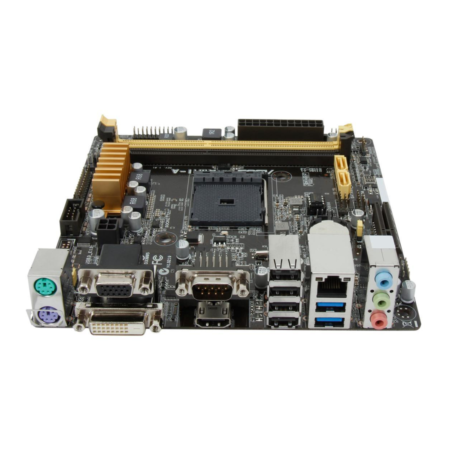
Place this side towards the rear of the chassis 1.2.3 Motherboard layout 17.0cm(6.7in) KBMS COM1 ATX12V Super USB1-4 CHA_FAN LAN_USB3_12 BIOS BATTERY 8111GR USB56 SATA6G_1 SATA6G_2 AUDIO USB78 PCIEX4 SPEAKER AAFP 15 14 11 10 Chapter 1: Product introduction... -
Page 11: Accelerated Processing Unit (Apu)
Ensure that you use an APU designed for the AM1 socket. The APU fits in only one correct orientation. DO NOT force the APU into the socket to prevent bending the pins and damaging the APU! AM1I-A APU socket AM1 ASUS AM1I-A... -
Page 12: Apu Installation
1.3.1 APU installation Chapter 1: Product introduction... -
Page 13: Apu Heatsink And Fan Assembly Installation
1.3.2 APU heatsink and fan assembly installation Apply the Thermal Interface Material to the APU heatsink and APU before you install the heatsink and fan if necessary. To install the APU heatsink and fan assembly ASUS AM1I-A... - Page 14 To uninstall the APU heatsink and fan assembly Chapter 1: Product introduction...
-
Page 15: System Memory
Channel Sockets Channel A DIMM_A1 & A2 AM1I-A 240-pin DDR3 DIMM sockets Ensure to insert the DIMM into DIMM_A2 socket if you install only one memory module. 1.4.2 Memory configurations You may install 1GB, 2GB, 4GB, 8GB and 16GB unbuffered non-ECC DDR3 DIMMs into the DIMM sockets. -
Page 16: Installing A Dimm
For system stability, use a more efficient memory cooling system to support a full memory load (2 DIMMs) or overclocking condition. • Visit the ASUS website at: www.asus.com for the latest QVL. 1.4.3 Installing a DIMM Chapter 1: Product introduction... -
Page 17: Expansion Slots
When using PCI cards on shared slots, ensure that the drivers support “Share IRQ” or that the cards do not need IRQ assignments. Otherwise, conflicts will arise between the two PCI groups, making the system unstable and the card inoperable. ASUS AM1I-A... -
Page 18: Pci Express X4 Slot
1.5.3 PCI Express x4 slot This motherboard has a PCI Express x4 slot that supports PCI Express x4 graphic card complying with the PCI Express specifications. IRQ assignments for this motherboard PCIEx4 shared – – – – – – Realtek LAN controller –... -
Page 19: Jumpers
CLRTC Normal Clear RTC (Default) AM1I-A Clear RTC RAM To erase the RTC RAM: Turn OFF the computer and unplug the power cord. Move the jumper cap from pins 1-2 (default) to pins 2-3. Keep the cap on pins 2-3 for about 5-10 seconds, then move the cap back to pins 1-2. - Page 20 DRAM in slow refresh, power supply in reduced power mode). KBMSPWR +5VSB (Default) AM1I-A Keyboard & Mouse wakeup The total current consumed must NOT exceed the power supply capability (+5VSB) whether under normal condition or in sleep mode. USB device wake-up (USBRPWR, USBPWR5~8) These jumpers allow you to enable or disable the USB device wake-up feature.
-
Page 21: Connectors
7.1-channel configurations, the function of this port becomes Front Speaker Out. Microphone port (pink). This port connects to a microphone. Refer to the audio configuration table on the next page for the function of the audio ports in 2.1, 4.1, 5.1 or 7.1-channel configuration. ASUS AM1I-A 1-13... - Page 22 Audio 2.1, 4.1, 5.1 or 7.1-channel configuration Headset Port 2.1- 4.1-channel 5.1-channel 7.1-channel channel Light Blue (Rear panel) Line In Rear Speaker Out Rear Speaker Out Rear Speaker Out Lime (Rear panel) Line Out Front Speaker Out Front Speaker Out Front Speaker Out Pink (Rear panel) Mic In...
-
Page 23: Internal Connectors
This connector is for a serial (COM1) port. Connect the serial port module cable to this connector, then install the module to a slot opening at the back of the system chassis. COM1 PIN 1 AM1I-A Serial port (COM1) connector The COM module is purchased separately. ASUS AM1I-A 1-15... -
Page 24: Atx Power Connectors
• If you are uncertain about the minimum power supply requirement for your system, refer to the Recommended Power Supply Wattage Calculator at http://support.asus. com/PowerSupplyCalculator/PSCalculator.aspx?SLanguage=en-us for details. LPT connector (26-1 pin LPT) The LPT (Line Printing Terminal) connector supports devices such as a printer. LPT standardizes as IEEE 1284, which is the parallel port interface on IBM PC-compatible computers. -
Page 25: Usb 2.0 Connectors 10-1 Pin Usb78/Usb910
These connectors are for the Serial ATA 6.0 Gb/s signal cables for Serial ATA hard disk drives and optical disc drives. AM1I-A SATA 6.0Gb/s connectors AHCI mode is not supported under Windows® 8 / Windows® 8.1 operating systems. Ensure to set the type of the SATA connectors to [IDE] from Advanced > SATA Configuration >... - Page 26 PIN 1 HD-audio-compliant Legacy ACʼ97 pin definition compliant definition AM1I-A Front panel audio connector • We recommend that you connect a high-definition front panel audio module to this connector to avail of the motherboard high-definition audio capability. • If you want to connect a high definition front panel audio module to this connector, set the Front Panel Type item in the BIOS to [HD].
-
Page 27: Speaker Connector 4-Pin Speaker
The 4-pin connector is for the chassis-mounted system warning speaker. The speaker allows you hear system beeps and warnings. SPEAKER PIN 1 AM1I-A Speaker Out Connector System panel connector (10-1 pin PANEL) This connector supports several chassis-mounted functions. F_PANEL (NC) -
Page 28: Onboard Leds
ON, in sleep mode, or in soft-off mode. This is a reminder that you should shut down the system and unplug the power cable before removing or plugging in any motherboard component. The illustration below shows the location of the onboard LED. SB_PWR AM1I-A Onboard LED 1-20 Chapter 1: Product introduction... -
Page 29: Software Support
The contents of the Support DVD are subject to change at any time without notice. Visit the ASUS website at www.asus.com for updates. To run the Support DVD Place the Support DVD into the optical drive. -
Page 30: Bios Information
Managing and updating your BIOS Save a copy of the original motherboard BIOS file to a USB flash disk in case you need to restore the BIOS in the future. Copy the original motherboard BIOS using the ASUS Update utility. -
Page 31: Asus Ez Flash
2.1.2 ASUS EZ Flash 2 The ASUS EZ Flash 2 feature allows you to update the BIOS without using an OS-based utility. Before you start using this utility, download the latest BIOS file from the ASUS website at www.asus.com. To update the BIOS using EZ Flash 2: Insert the USB flash disk that contains the latest BIOS file to the USB port. -
Page 32: Asus Crashfree Bios 3 Utility
2.1.3 ASUS CrashFree BIOS 3 utility The ASUS CrashFree BIOS 3 is an auto recovery tool that allows you to restore the BIOS file when it fails or gets corrupted during the updating process. You can restore a corrupted BIOS file using the motherboard support DVD or a USB flash drive that contains the updated BIOS file. - Page 33 Insert the USB flash drive with the latest BIOS file and BIOS Updater to the USB port. Boot your computer. When the ASUS Logo appears, press <F8> to show the BIOS Boot Device Select Menu. Insert the support DVD into the optical drive and select the optical drive as the boot device.
- Page 34 Ensure to load the BIOS default settings to ensure system compatibility and stability. Select the Load Optimized Defaults item under the Exit menu. Refer to section 2.10 Exit menu for details. • Ensure to connect all SATA hard disk drives after updating the BIOS file if you have disconnected them. ASUS AM1I-A...
-
Page 35: Bios Setup Program
BIOS setup program Use the BIOS Setup program to update the BIOS or configure its parameters. The BIOS screens include navigation keys and brief online help to guide you in using the BIOS Setup program. Entering BIOS Setup at startup To enter BIOS Setup at startup: •... -
Page 36: Advanced Mode
The Advanced Mode provides advanced options for experienced end-users to configure the BIOS settings. The figure below shows an example of the Advanced Mode. Refer to the following sections for the detailed configurations. To access the EZ Mode, click Exit, then select ASUS EZ Mode or press F7. ASUS AM1I-A... -
Page 37: Menu Bar
Back button Menu items Menu bar Configuration fields General help Last modified Submenu item Navigation keys Pop-up window settings Quick note Menu bar The menu bar on top of the screen has the following main items: My Favorites For saving the frequently-used system settings and configuration Main For changing the basic system configuration Ai Tweaker... -
Page 38: Scroll Bar
The Quick Note function does not support the following keyboard functions: delete, cut, copy and paste. • You can only use the English letters to type your notes. Last Modified button This button shows the items that you last modified and saved in BIOS Setup. ASUS AM1I-A... -
Page 39: My Favorites
My Favorites MyFavorites is your personal space where you can easily save and access your favorite BIOS items. Adding items to My Favorites To add frequently-used BIOS items to My Favorites: Use the arrow keys to select an item that you want to add. When using a mouse, hover the pointer to the item. -
Page 40: Main Menu
Otherwise, you might be able to see or change only selected fields in the BIOS setup program. To set an administrator password: Select the Administrator Password item and press <Enter>. From the Create New Password box, key in a password, then press <Enter>. ASUS AM1I-A 2-11... -
Page 41: User Password
Confirm the password when prompted. To change an administrator password: Select the Administrator Password item and press <Enter>. From the Enter Current Password box, key in the current password, then press <Enter>. From the Create New Password box, key in a new password, then press <Enter>. Confirm the password when prompted. -
Page 42: Ai Tweaker Menu
This item appears only when you set the Ai Overclock Tuner item to [Manual]. Use the <+> and <-> keys to adjust the value. You can also key in the desired value using the numeric keypad. The values range from 90.0MHz to 300.0MHz. ASUS AM1I-A 2-13... -
Page 43: Dram Timing Control
2.5.2 Memory Frequency [Auto] Allows you to set the memory operating frequency. Configuration options: [Auto] [DDR3- 800MHz] [DDR3-1066MHz] [DDR3-1333MHz] [DDR3-1600MHz] Selecting a very high memory frequency may cause the system to become unstable! If this happens, revert to the default setting. 2.5.3 APU Multiplier [Auto] Allows you to set the multiplier between the APU Core Clock and the APU Bus Frequency. -
Page 44: Advanced Menu
The Advanced menu items allow you to change the settings for the CPU and other system devices. Be cautious when changing the settings of the Advanced menu items. Incorrect field values can cause the system to malfunction. ASUS AM1I-A 2-15... -
Page 45: Cpu Configuration
2.6.1 CPU Configuration The items in this menu show the CPU-related information that the BIOS automatically detects. The items shown in submenu may be different due to the CPU you installed. AMD PowerNow function [Enabled] Enables or disables the AMD PowerNow function. Configuration options: [Enabled] [Disabled] NX Mode [Enabled] Enables or disables the No-execute page protection function. -
Page 46: Usb Configuration
Allows you to enable/disable individual USB ports. USB3_1,2 [Enabled] Allows you to enable or disable an individual USB3.0 port. Refer to the section 1.2.3 Motherboard layout in this user manual for the locations of the USB ports. Configuration options: [Enabled] [Disabled]. ASUS AM1I-A 2-17... -
Page 47: Onboard Devices Configuration
USB 1~8 [Enabled] Allows you to enable or disable an individual USB port. Refer to the section 1.2.3 Motherboard layout in this user manual for the locations of the USB ports. Configuration options: [Enabled] [Disabled]. 2.6.4 NB Configuration iGFX Multi-Monitor [Disabled] Set this item to [Enabled] to empower both integrated and discrete graphics for multiple- monitor output. -
Page 48: Serial Port Configuration
Device Mode [STD Printer Mode] Allows you to change the printer port mode. Configuration options: [STD Printer Mode] [SPP Mode] [EPP-1.9 and SPP Mode] [EPP-1.7 and SPP Mode] [ECP Mode] [ECP and EPP 1.9 Mode] [ECP and EPP 1.7 Mode] ASUS AM1I-A 2-19... - Page 49 2.6.6 Deep S4 [Disabled] When enabled, the system in S4 state will further reduce power usage and will power off the USB and PS/2 devices. The system in deep S4 state can be woken up via the power button, devices in LAN, or other ways except via the USB and PS/2 devices. Configuration options: [Disabled] [Enabled] Restore AC Power Loss [Power Off] [Power On]...
-
Page 50: Monitor Menu
Ipv6 PXE Support [Enabled] This item allows user to disable or enable the Ipv6 PXE Boot support. Configuration options: [Disabled] [Enabled] Monitor menu The Monitor menu displays the system temperature/power status, and allows you to change the fan settings. ASUS AM1I-A 2-21... - Page 51 Scroll down to display the following items: 2.7.1 CPU Temperature / MB Temperature [xxxºC/xxxºF] The onboard hardware monitor automatically detects and displays the CPU and motherboard temperatures. Select Ignore if you do not wish to display the detected temperatures. 2.7.2 CPU / ChA Fan Speed [xxxx RPM] or [Ignore] / [N/A] The onboard hardware monitor automatically detects and displays the CPU / chassis fan 1/2 speeds in rotations per minute (RPM).
- Page 52 2.7.5 CPU Voltage, 3.3V Voltage, 5V Voltage, 12V Voltage The onboard hardware monitor automatically detects the voltage output through the onboard voltage regulators. Select Ignore if you do not want to detect this item. ASUS AM1I-A 2-23...
-
Page 53: Boot Menu
2.7.6 Anti Surge Support [Disabled] This item allows you to enable or disable the Anti Surge function. Configuration options: [Disabled] [Enabled] Boot menu The Boot menu items allow you to change the system boot options. Scroll down to display the following items: 2-24 Chapter 2: BIOS information... - Page 54 Select to load the network stack driver during POST. Next Boot after AC Power Loss [Normal Boot] [Normal Boot] Returns to normal boot on the next boot after AC power loss. [Fast Boot] Accelerates the boot speed on the next boot after AC power loss. ASUS AM1I-A 2-25...
- Page 55 2.8.2 Boot Logo Display [Auto] [Auto] Adjust automatically for Windows® requrement. [Full Screen] Maximize the boot logo size. [Disabled] Hide the logo during POST. POST Delay Time [3 sec] This item appears only when you set Full Screen Logo to [Enabled]. This item allows you to select the desired additional POST waiting time to easily enter the BIOS setup.
-
Page 56: Secure Boot
® ® or other Microsoft Secure Boot non-compliant ® OS. Only on Windows UEFI mode that Microsoft ® ® Secure Boot can function properly. The following item appears when OS Type is set to [Windows UEFI mode]. ASUS AM1I-A 2-27... -
Page 57: Key Management
Key Management This item appears only when you set OS Type to [Windows UEFI mode]. It allows you to manage the Secure Boot keys. Install Default Secure Boot keys Allows you to immediately load the default Security Boot keys, Platform key (PK), Key-exchange Key (KEK), Signature database (db), and Revoked Signatures (dbx). -
Page 58: Boot Option Priorities
• To select the boot device during system startup, press <F8> when ASUS Logo appears. • To access Windows OS in Safe Mode, press <F8> after POST. -
Page 59: Tools Menu
<Enter> to display the submenu. 2.9.1 ASUS EZ Flash 2 Utility Allows you to run ASUS EZ Flash 2. Press [Enter] to launch the ASUS EZ Flash 2 screen. For more details, see section 2.1.2 ASUS EZ Flash 2. 2.9.2 ASUS O.C. -
Page 60: Exit Menu
This option allows you to exit the Setup program without saving your changes. When you select this option or if you press <Esc>, a confirmation window appears. Select Yes to discard changes and exit. ASUS EZ Mode This option allows you to enter the EZ Mode screen. Launch EFI Shell from filesystem device This option allows you to attempt to launch the UEFI Shell application (shellx64.efi) from one... - Page 61 2-32 Chapter 2: BIOS information...
-
Page 62: Appendices
Cet appareil est conforme aux normes CNR exemptes de licence d’Industrie Canada. Le fonctionnement est soumis aux deux conditions suivantes : (1) cet appareil ne doit pas provoquer d’interférences et (2) cet appareil doit accepter toute interférence, y compris celles susceptibles de provoquer un fonctionnement non souhaité de l’appareil. ASUS AM1I-A... -
Page 63: Canadian Department Of Communications Statement
ASUS Recycling/Takeback Services ASUS recycling and takeback programs come from our commitment to the highest standards for protecting our environment. We believe in providing solutions for you to be able to responsibly recycle our products, batteries, other components as well as the packaging materials. -
Page 64: Asus Contact Information
+1-510-608-4555 Web site http://usa.asus.com Technical Support Support fax +1-812-284-0883 General support +1-812-282-2787 Online support http://support.asus.com/techserv/techserv.aspx ASUS COMPUTER GmbH (Germany and Austria) Address Harkort Str. 21-23, D-40880 Ratingen, Germany +49-2102-959931 Web site http://www.asus.com/de Online contact http://eu-rma.asus.com/sales Technical Support Telephone (Component) +49-2102-5789555... - Page 65 Appendices...