Table of Contents

Related Manuals for Casio CTK-650


Summary of Contents for Casio CTK-650
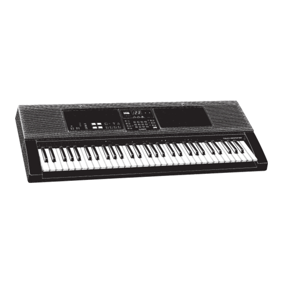
- Page 1 (with price) CTK-650 CTK-650 ELECTRONIC KEYBOARD...
-
Page 2: Table Of Contents
CONTENTS SPECIFICATIONS ....................1 BLOCK DIAGRAM ....................2 CIRCUIT DESCRIPTION CPU (HD6433298A16P : H8/329) ..............3 DIGITAL SIGNAL PROCESSOR, LSI-S (HG51A115A01FD) ......4 KEY TOUCH LSI (HG52E35P) ................5 POWER AMPLIFIER (LA4598) .................6 BUTTON MATRIX ..................... KEY MATRIX .....................8 WIRING DIAGRAM ....................IC LEAD IDENTIFICATION AND INTERNAL CIRCUIT ..........10 PCB VIEW AND MAJOR WAVEFORMS .............. -
Page 3: Specifications
TONE STACK KEY SPLIT HYPERACTIVE Auto-accompaniment: Rhythm patterns Tempo Adjustable(40 - 255) Chords Three system: CASIO CHORD, FINGERD, FULL-RANGE CHORD Other Variation pattern, fill-in pattern, intro/ending pattern for each rhythm. Song memory: song:one System:Real-time recording Memory capacity:Up to 1,300 notes... -
Page 4: Block Diagram
BLOCK DIAGRAM 7-Segment LO0~LO4 LED driver RAM-1(64K) BA612 MN4464-08L-1 KO0~KO5 Key Touch D0~D7 KC0~KC7 Buttons HD6433298A16P Address Bus Keyboard (H8/329) KI1~KI7 HG52E35P SI0~SI7 FI0~FI7 100K MIDI Power Switch EA0~EA12 RA0~RA19 RAM-2(64K) LSI-S ROM(16M) MN4464-08L-2 HG51A115A01FD TC5316200CP-C079 ED0~ED7 RD0~RD15 WCK1 SLOP D/A Converter µPD6376CX Filter... -
Page 5: Circuit Description
CIRCUIT DESCRIPTION CPU(HD6433298A16P : H8/329) The 16-bit CPU contains a 32K-byte ROM, a 1K-byte RAM, an 8-bit A/D converter, timers and I/O ports. The CPU accesses to the DSP, Key Touch LSI, RAM, buttons and LEDs. But the CPU directly receives MIDI and pedal signals. -
Page 6: Digital Signal Processor, Lsi-S (Hg51A115A01Fd)
DIGITAL SIGNAL PROCESSOR, LSI-S (HG51A115A01FD) The LSI-S is a 16-bit DSP(Digital Signal Processor) and accessable to 16M-bit sound source ROM and to 64K- bit RAM. The DSP can read data of 32 polyphonic note from the ROM and provides two 16-bit serial dat with timing signals to each channel's D/A converter. -
Page 7: Key Touch Lsi(Hg52E35P)
KEY TOUCH LSI(HG52E35P) By counting the time between the first key input signal FI and the second SI from the keyboard unit, the key touch LSI detects key velocity of 256-step. Then the LSI sends the CPU note numbers and their velocities. Key Touch LSI HD6433298A16P HG52E35P... -
Page 8: Power Amplifier(La4598)
POWER AMPLIFIER(LA4598) LA4598 is 2-channel power amplifier with standby switch. Pin No. Terminal In/Out Function Power GND Ground(0V) source. Ch1 B.S. Terminal for bootstrap capacitor. Ch1 OUT Channel 1 output. +9V source. Ch1 N.F. Negative feedback input. Ch1 IN Channel 1 input. D.C. -
Page 9: Button Matrix
BUTTON MATRIX K I 1 K I 2 K I 3 K I 4 K I 5 K I 6 K I 7 ACCOMP K O 0 SONG NO. VOLUME REGIST- TOUCHCOVE MULTI K O 1 SPLIT RATION DEMO LAYER ON/OFF EFFECTOR MEMORY... -
Page 10: Key Matrix
KEY MATRIX C2 1 C#2 1 D2 1 D#2 1 E2 1 F2 1 F#2 1 G2 1 C2 2 C#2 2 D2 2 D#2 2 E2 2 F2 2 F#2 2 G2 2 G#2 1 A2 1 A#2 1 B2 1 C3 1 C#3 1... -
Page 11: Wiring Diagram
WIRING DIAGRAM M616T-KY2M M616T-KY1M JA CONNECTOR JB-CONNECTOR JB-CONNECTOR JA-CONNECTOR DC JACK PHONES/OUTPUT SUSTAIN M5711-MA1M MIDI IN MIDI OUT JC-CONNECTOR JD-CONNECTOR BATTERY COMPARTMENT JD-CONNECTOR JC-CONNECTOR M5711-CN1M — 9 —... -
Page 12: Ic Lead Identification And Internal Circuit
IC LEAD IDENTIFICATION AND INTERNAL CIRCUIT UPD6376CX (D/A converter) MAIN DAC L.OUT LRCK SUB DAC L.REF LRSEL/RSI SI/LSI SUB DAC R.REF 4/8 fs SEL MAIN DAC R.OUT D.GND A.VDD A.GND N.C. D.VDD TC74HC174AP (HEX D-TYPE FLIP FLOP WITH CLEAR ) CLEAR CK Q CK Q... - Page 13 M5218APR S-8053ANO 1 OUT S-81350HG S-8053ANO 2SB1274 B C E 2SC1740 DTA114TS 2SB1240 2SA933 2SD1858 E C B — 11 —...
-
Page 14: Pcb View And Major Waveforms
PCB VIEW & MAJOR WAVEFORMS 10 11 12 13 — 12 —... -
Page 15: Schematic Diagram
SCHEMATIC DIAGRAM M5711-MA1M 10 11 12 13 — 13 —... - Page 16 SCHEMATIC DIAGRAM M5711-CN1M — 14 —...
-
Page 17: Parts List
PARTS LIST CTK-650 Notes: 1. Prices and specifications are subject to change with- out prior notice. 2. As for spare parts order and supply, refer to the "GUIDEBOOK for Spare parts Supply", published separately. 3. The numbers in item column correspond to the same... - Page 18 FOB Japan Item Code No. Parts Name Specification N.R.Yen Unit Price PCB ass'y M5711-MA1M 2011 3325 LSI UPD6376CX 2011 5194 LSI HG52E35P 2011 5201 LSI HG51A115A01FD 2,820 2011 6797 LSI LC3564Q-85.10 2011 6944 LSI TC5316200CP-C079 1,230 2011 7021 LSI HD6433298A16P 2105 2114 IC, Regulator S-81350HG 2105 2219 MOS IC...
- Page 19 FOB Japan Item Code No. Parts Name Specification N.R.Yen Unit Price 2765 1344 Slide volume EWA-MJCC25B23 2801 7910 Electrolytic capacitor 16RE3-470-T2-T 3 10 2805 2341 Electrolytic capacitor 10RE2-1000-S1 2 10 2805 3061 Electrolytic capacitor 6.3RE2-220-T2-T 2 10 2805 3134 Electrolytic capacitor 10RE2-22-T2-T 11 20 2805 3142 Electrolytic capacitor...
- Page 20 FOB Japan Item Code No. Parts Name Specification N.R.Yen Unit Price Mechanical Parts 6922 3800 Display window 711 M312128-1 6921 5040 Slide volume knob 601 M311860-1 1 10 6922 3820 Panel 711 M111744-1 6922 3830 Rubber button 711A M312122-1 1 10 6922 3840 Rubber button 711B M312123-1 1 10...
-
Page 21: Exploded View
EXPLODED VIEW... - Page 22 MA0200941A...