Table of Contents
Advertisement
Quick Links
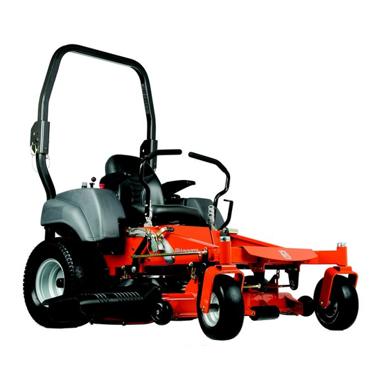
Operator Manual
Gasoline containing up to
10% ethanol (E10) is acceptable
for use in this machine.
MZ5424SR CA / 967003904
The use of any gasoline exceeding
10% ethanol (E10) will void the
product warranty.
Please read the operator manual carefully and make sure
you understand the instructions before using the machine.
Advertisement
Table of Contents

Related Manuals for Husqvarna MZ5424SR CA


Summary of Contents for Husqvarna MZ5424SR CA
- Page 1 Operator Manual Gasoline containing up to 10% ethanol (E10) is acceptable for use in this machine. MZ5424SR CA / 967003904 The use of any gasoline exceeding 10% ethanol (E10) will void the product warranty. Please read the operator manual carefully and make sure...
- Page 2 To implement improvements, specifications and designs can be altered without prior notification. Note that no legal demands can be placed based on the information contained in these instructions. Use only original parts for repairs. The use of other parts voids the warranty. Do not modify or install non-standard equipment to the unit without consent from the manufacturer.
-
Page 3: Table Of Contents
CONTENTS INTRODUCTION ............5 Running ............31 Driving and Transport on Public Roads .....5 Operating on Hills ..........32 Towing ..............5 Stopping the Engine .........33 Operating ............5 Mowing Tips .............34 Good Service .............6 Moving Machine By Hand ........35 Manufacturing Number .........6 MAINTENANCE ............36 SYMBOLS AND DECALS .........7 Maintenance Schedule ........36 SAFETY ..............9... - Page 4 WARNING! Failure to follow cautious operating practices can result in serious injury to the operator or other persons. The owner must understand these instructions, and must allow only trained persons who understand these instructions to operate the mower. Each person operating the mower must be of sound mind and body and must not be under the influence of any mind altering substance.
-
Page 5: Introduction
INTRODUCTION Congratulations Towing Thank you for purchasing a Husqvarna ride-on mower. If machine is equipped with a tow hitch, use extreme This machine is built for superior efficiency to rapidly caution when towing. Never allow children or others in mow primarily large areas. A control panel that is or on the towed equipment. -
Page 6: Good Service
INTRODUCTION Good Service Husqvarna's products are sold only in specialized retail stores with complete service. This ensures that you as a customer receive only the best support and service. Before the product is delivered, the machine has, for example, been inspected and adjusted by your retailer. -
Page 7: Symbols And Decals
SYMBOLS AND DECALS These symbols are found on the machine and in the operator manual. Study them carefully so that you know what they mean. WARNING! IMPORTANT INFORMATION Xxxx xxxxxx xxxxx xxxx xxxxxxxxx Xxxx xxxxxx xxxxx xxxx xxxxxxxxx xxxxxx xxxxxx xxxxxxxxx. xx xxxxxxxx xxxx xxxxxxxxx. - Page 8 SYMBOLS AND DECALS Shut off engine and remove key before performing any Keep a safe maintenance distance from the Use on slopes no Read Operator Manual or repair work machine greater than 10° No passengers Whole body exposure Severing of fingers Do not open or Careful backing up, Careful going forward,...
-
Page 9: Safety
SAFETY Safety Instructions These instructions are for your safety. Read them carefully. WARNING! WARNING! THIS CUTTING MACHINE IS CAPABLE This symbol means that important safety OF AMPUTATING HANDS AND FEET instructions need to be emphasized. It AND THROWING OBJECTS. FAILURE concerns your safety. - Page 10 SAFETY • Disengage blades when not mowing. Shut off engine and wait for all parts to come to a complete stop before cleaning the machine, removing the grass catcher, or unclogging the discharge guard. • Operate machine only in daylight or good artificial light.
-
Page 11: Personal Safety Equipment
SAFETY Personal Safety Equipment WARNING! When using the machine, approved personal protective equipment (shown in illustrations) shall be used. Personal protective equipment cannot eliminate the risk of injury but it will reduce the degree of injury if an accident does happen. - Page 12 SAFETY • Do not try to stabilize the machine by putting a foot on the ground. • Do not mow near drop-offs, ditches, or embankments. The machine could suddenly roll over if a wheel is over the edge or if the edge caves in.
-
Page 13: Safe Handling Of Gasoline
SAFETY Safe Handling of Gasoline WARNING! The engine and the exhaust system become very hot during operation. There is risk for burns if touched. Allow engine and exhaust system to cool before refueling. To avoid personal injury or property damage, use extreme care in handling gasoline. -
Page 14: General Maintenance
SAFETY General Maintenance • Never operate machine in a closed area. • Keep all nuts and bolts tight to be sure the equipment is in safe working condition. • Never tamper with safety devices. Check their proper operation regularly. • Keep machine free of grass, leaves, or other debris buildup. - Page 15 SAFETY Sparking can occur when working with the battery and the heavy cables of the starter circuit. This can cause battery explosion, fire or eye injury. Sparking in this circuit can not occur after the chassis cable (normally negative, black) is removed from the battery. WARNING! Avoid electrical sparking and its consequences by the following routines:...
-
Page 16: Transport
Code). arrestor is used, it should be maintained Other states may have similar laws. Federal laws in effective working order by the apply on federal lands. operator. A spark arrestor for the muffler is available through any authorized Husqvarna dealer. -
Page 17: Rollover Protection System (Rops)
SAFETY Rollover Protection System (ROPS) WARNING! The ROPS increases the basic weight of the unit by 73 The rollover protection system's lbs/33 kg. capabilities may be impaired by damage • Do not use ROPS as a lifting, attaching or if the mower is overturned or if alteration anchoring point. -
Page 18: Controls
CONTROLS This operator manual describes the Husqvarna Zero hydraulic pumps. Using the left and right steering Turn Rider. The rider is fitted with a Kawasaki four- controls, the flow is regulated and thereby the stroke overhead valve engine. direction and speed. -
Page 19: Motion Control Levers
CONTROLS Motion Control Levers The machine’s speed and direction are continuously variable using the two steering controls. The steering controls can be moved forward or backward about a neutral position. Furthermore, there is a neutral position, which is locked if the steering controls are moved outward. -
Page 20: Parking Brake
CONTROLS Parking Brake The parking brake is found on the left of the machine. Pull the lever backward to activate the brake and push forward to release it. IMPORTANT INFORMATION The machine must stand absolutely still when applying the parking brake. Always set the parking brake before dismounting. -
Page 21: Ignition Switch
CONTROLS Ignition Switch The ignition switch is placed on the control panel and is used to start and stop the engine. Turn the key clockwise to start the engine. 8058-145 Ignition switch Choke Control The choke control is used for cold starts in to provide the engine with a richer fuel mixture. -
Page 22: Fuel Tank
CONTROLS Fuel Tank Read the safety instructions before refueling. The capacity for the tank is 5 gallons (19 liters). Regularly check the gas cap gasket for damage and keep the cap properly tightened. The engine will run on a minimum of 87-octane unleaded gasoline (no oil mix). -
Page 23: Fuel Shut Off Valve
CONTROLS Fuel Shut Off Valve The fuel shut off valve is centered behind the rear of the seat. The valve is off when the handle tab is turned perpendicular to the fuel line. IMPORTANT INFORMATION Always raise the deck to the highest position for transport. -
Page 24: Seat Adjustment Lever
CONTROLS Seat Adjustment Lever The seat can be adjusted lengthways. When making adjustments, the lever under the front edge of the seat is moved to the left (as seen by the driver in the seat), after which the seat can be moved backward or forward. -
Page 25: Operation
OPERATION line. Pull the control levers back to the neutral position Read the Safety section and the following pages if and the mower should stop moving. you are unfamiliar with the machine. Pull back slightly on control levers, allowing the mower Training to move backwards. -
Page 26: Before Starting
OPERATION Before Starting 1. Read the sections on Safety and Controls before starting the machine. 2. Perform the daily maintenance before starting (see Maintenance Schedule in the Maintenance section). 3. Check that there is sufficient fuel in the fuel tank. 4. -
Page 27: Starting The Engine
OPERATION Starting the Engine 1. Sit on the seat. 2. Raise the mower deck to the transport position by locking the lift pedal fully forward. 8058-223 Set mower deck to the transport position 3. Activate the parking brake. 8058-210 Activate parking brake before starting 4. - Page 28 OPERATION 5. Move the steering controls outward to the locked (outer) neutral position. 8058-208 Place controls in neutral position 6. Move the throttle to the middle position. If the engine is cold, the choke control should be pulled 8058-145 Set the throttle and choke 7.
- Page 29 OPERATION 8. Press in and turn the ignition key to the start position. IMPORTANT INFORMATION Do not run the starter for more than 5 seconds each time. If the engine does not start, wait about 10 seconds before retrying. 8050-780 Turn to the start position 9.
-
Page 30: Jumper Cables Use
OPERATION Weak Battery WARNING! Lead-acid batteries generate explosive gases. Keep sparks, flame and smoking materials away from batteries. Always wear eye protection when around batteries. IMPORTANT INFORMATION The mower is equipped with a 12-volt negative grounded system. The other vehicle must also be a 12-volt negative grounded system. -
Page 31: Running
OPERATION Running 1. Release the parking brake by moving the lever downward. NOTE: The mower is equipped with an operator presence system. When the engine is running, any attempt by the operator to leave the seat without first setting the parking brake will shut off the engine. -
Page 32: Operating On Hills
OPERATION Operating on Hills Read the Safety Instructions Driving on Slopes in the Safety section. WARNING! Do not drive up or down hills with slopes greater than 10 degrees. Do not drive across slopes. • The slowest speed possible should be used before starting up or down hills. -
Page 33: Stopping The Engine
OPERATION Stopping the Engine 1. Move the throttle to the minimum position (tortoise symbol). 2. Move the steering controls outward. 3. Disengage the mower deck by depressing the blade switch. 8058-160 Disengage the mower deck and move throttle to minimum 4. -
Page 34: Mowing Tips
OPERATION Mowing Tips WARNING! • Observe and flag rocks and other fixed objects to Clear the lawn of stones and other avoid collisions. objects that can be thrown out by the • Begin with a high cutting height and reduce it blades. -
Page 35: Moving Machine By Hand
OPERATION Moving Machine By Hand When pushing or pulling the mower, engage the IZT (Integrated Zeroturn Transaxle) bypass linkages. The release levers are located on each side of the rear of the unit below the rear engine plate. 1. Raise the deck to the highest (transport) position. 2. -
Page 36: Maintenance
MAINTENANCE Maintenance Schedule The following is a list of maintenance procedures that an authorized service workshop is recommended to must be performed on the machine. For those points maintain your machine in the best possible condition not described in this manual, visit an authorized and to ensure safe operation. - Page 37 MAINTENANCE Daily At least Maintenance interval once in hours each year MAINTENANCE Before After ■ Check/adjust throttle cable ● ● Check the condition of belts, belt pulleys ■ ■ Change the engine oil ■ ■ Replace the engine oil filter ■...
-
Page 38: Battery
MAINTENANCE Battery STANDARD STATE APPROXIMATE BATTERY CHARGING TIME* TO FULL CHARGE AT 80 F / 27 Your mower is equipped with a maintenance free BATTERY Maximum Rate at: battery and does not need servicing. However, CHARGE 50 Amps 30 Amps 20 Amps 10 Amps periodic charging of the battery with an automotive... -
Page 39: Safety System
MAINTENANCE Safety System This machine is equipped with a safety system that prevents starting or driving under the following conditions. The engine can only be started when: 1. The mower deck is disengaged. 2. The steering controls are in the outer, locked neutral position. -
Page 40: Deck Belt
MAINTENANCE Deck Belt Deck Belt Removal Park on a level surface. Apply park brake. Lower the deck into the lowest cutting position. 1. Remove foot plate and belt shields. 2. Using a ratchet or breaker bar with a " socket on the spring idler bolt, relieve the tension on the belt. -
Page 41: Pump Belt
MAINTENANCE Pump Belt The belts are not adjustable. Replace belts if they begin to slip from wear. Replacing Pump Belt Park the mower on a level surface. Engage the parking brake. Belt Removal From the top side of the deck: 1. -
Page 42: Cutting Blades
Spindle housing 4. Tighten blade bolt securely. Blade attachment 5. Torque blade bolt to 40-55 ft/lbs (54-75 Nm). IMPORTANT INFORMATION Special blade bolt is heat treated. Replace with a Husqvarna bolt if required. Do not use lower grade hardware than specified. -
Page 43: Adjusting The Mower Deck
MAINTENANCE Adjusting the Mower Deck Check the tire pressure before adjustment of the mower deck. See Tire Pressures in Maintenance section. Faulty mower deck adjustments will cause an uneven mowing result. Leveling deck Adjust the deck while the mower is on a level surface. -
Page 44: Anti-Scalp Rollers
MAINTENANCE Anti-scalp rollers Anti-scalp rollers are properly adjusted when they are just slightly off of the ground when the deck is at the desired cutting height in the operating position. Anti- scalp rollers then keep the deck in the proper position to help prevent scalping in most terrain conditions. -
Page 45: Caster Wheels
MAINTENANCE Caster Wheels Check every 200 hours. Check that wheels rotate freely. IMPORTANT INFORMATION DO NOT add any type of tire liner or foam fill material to the tires. Excessive loads created by foam tires will cause premature failures. Use only O.E.M. specified tires. Removal and Installation Remove nut and caster bolt. -
Page 46: Lubrication
LUBRICATION Lubrication Schedule 8058-258 12/12 Every year Lubricate with grease gun Filter change 1/52 Every Week 1/365 Every day Oil change Level check Change hydraulic drive filters. p See Engine Manufacturer's manual General Remove the ignition key to prevent unintentional Wipe away excess grease after lubrication. -
Page 47: Engine Oil Change
LUBRICATION Engine Oil Change WARNING! NOTE: Change the engine oil when the engine To prevent burns, the engine should is warm. Refer to the engine owner’s manual be shut off and allowed to cool slightly for the correct replacement oil and filter change so the engine is still warm but the recommendations. -
Page 48: Transaxle (Transmission) Fluid Change
LUBRICATION Deck Spindles Lower the cutting deck completely. If a grease gun without rubber hose is used, the foot plate must be removed to access the center spindle. Lubricate with a grease gun, 2-3 strokes per spindle. 8058-153 Deck spindle Transaxle (Transmission) Fluid Change This transaxle is designed with an external filter for ease of maintenance. -
Page 49: Purge Procedure
LUBRICATION 7. Drain old oil filters of all free flowing oil prior to Purge Procedure disposal. Place used oil in appropriate containers Transmission Purging and dispose of it in accordance with laws in your Due to the effects air has on efficiency in hydrostatic area. -
Page 50: Troubleshooting Guide
TROUBLESHOOTING Problem Cause Engine will not start • Blade switch is engaged • Steering controls are not locked in the neutral position • Parking brake is not activated • Battery is dead • Contamination in the carburetor or fuel line •... - Page 51 TROUBLESHOOTING Problem Cause Machine vibrates • Blades are loose • Blades are incorrectly balanced • Engine is loose • Blades are bent Engine overheats • Clogged air intake or cooling fins • Engine overloaded • Poor ventilation around engine • Defective engine speed regulator •...
-
Page 52: Storage
Drain the fuel into an purchase year, model, type, and serial number. approved container outdoors and store Always use genuine Husqvarna spare parts. far away from open flame. Never use An annual check-up at an authorized service gasoline for cleaning. Use a degreaser workshop is a good way to ensure that the machine and warm water instead. -
Page 53: Wiring Diagrams
WIRING DIAGRAM... -
Page 54: Technical Data
TECHNICAL DATA The power rating as declared by the MZ5424SR CA / 967003904 engine manufacturer is the average gross power output at the specified RPM of a Engine typical production engine for the engine Manufacturer Kawasaki model measured using SAE Standards for engine gross power. - Page 55 TECHNICAL DATA MZ5424SR CA / 967003904 Frame Cutting Width 54" (137 cm) Cutting Height 1½"-4½" (3.8-11.4 cm) Uncut Circle Number of Blades Blade Length 18" / 46 cm Nose Roller Seat Standard w/ slides Hinged Arm Rests Hour Meter Blade Engagement...
-
Page 56: Torque Specifications
TECHNICAL DATA Torque Specifications Engine crankshaft bolt 50 ft/lb (67 Nm) Standard ¼" fasteners 9 ft/lb (12 Nm) Deck pulley bolts 20 ft/lb (23 Nm) Standard " fasteners 18 ft/lb (25 Nm) Lug nuts 75 ft/lb (100 Nm) Standard " fasteners 33 ft/lb (44 Nm) Blade bolt 55 ft/lb (75 Nm) -
Page 57: Conformity Certificates
CONFORMITY CERTIFICATES USA requirements Labels are placed on the engine and/or in the engine compartment stating that the machine will fulfill the requirements. This is also applicable to special requirements for any of the states, (California emission rules etc.). Do not remove any of these labels. Certificates can also be supplied with the machine at delivery or written in the Engine manual. -
Page 58: Service Journal
SERVICE JOURNAL Action Date, mtr reading, stamp, sign Delivery Service Charge the battery Adjust the tire pressure of all wheels to 15 PSI (1 bar) Mount the steering controls in the normal position Connect the contact box to the cable for the seat’s safety switch Check that the right amount of oil is in the engine Adjust the position of the steering controls Fill with fuel and open the fuel shut off valve... - Page 59 SERVICE JOURNAL Action Date, mtr reading, stamp, sign After 10 hours Change the engine oil Inspect hydraulic hoses Inspect hydraulic belt Inspect hydraulic filter Check neutral position Check safety system Check seat belt Check fuel system for leaks Inspect safety guards and shields Check brake adjustment Daily Service Clean debris from mower...
- Page 60 SERVICE JOURNAL Action Date, mtr reading, stamp, sign 50-Hour Service Check the fuel pump’s air filter Sharpen/Replace mower blades if required Check the tire pressures Check battery and cables Lubricate according to lubrication chart Check/clean the engine’s cooling air intake Clean the air cleaner’s foam pre-filter...
- Page 61 SERVICE JOURNAL Action Date, mtr reading, stamp, sign 250-Hour Service Grease fittings (caster pivots and caster wheels) Inspect dampeners Inspect frame Inspect throttle cable Inspect hardware Check the tire pressures Change the engine oil and filter Change air filter Inspect spark plug Inspect fuel filter Check engine RPM Clean underside of deck...
- Page 62 SERVICE JOURNAL Action Date, mtr reading, stamp, sign 500-Hour Service Grease fittings (caster pivots and caster wheels) Inspect dampeners Inspect frame Inspect throttle cable Inspect hardware Check the tire pressures Change the engine oil and filter Change air filter Inspect spark plug Inspect fuel filter Check engine RPM Clean underside of deck...
- Page 63 SERVICE JOURNAL Action Date, mtr reading, stamp, sign At least once each year Clean the engine’s cooling air intake. Replace the air cleaner’s pre-filter (foam). Replace the air filter’s paper cartridge. Change the engine oil. Replace the engine oil filter Check/adjust the cutting height Check/adjust the parking brake Clean/change the spark plugs...
- Page 64 2013-08-15 115 605327 Rev B...