Table of Contents
Advertisement
Advertisement
Table of Contents

Related Manuals for Honda EX350


Summary of Contents for Honda EX350
- Page 1 -e. Owner’s Manual EX350...
- Page 2 The generator is a potential source of electrical shock if misused. Do not expose the generator to moisture, rain or snow. Do not let the generator get wet, and do not operate it with wet hands.
- Page 3 Thank you for purchasing a Honda generator. This manual covers the operation and maintenance of the EX350 generator. The EX350 is equipped for manual starting only. All information in this publication is based on the latest product information available at the time of printing.
-
Page 4: Table Of Contents
CONTENTS 1. SAFETY ... Safety Label Location ... Safety Information ... 2: COMPONENT IDENTIFICATION ... 3. PRE-OPERATION CHECKS ... 4. STARTING THE ENGINE ... 6. GENERATOR USE ... AC Applications Output and Overload Indicators ... DC Application ... High Altitude Operation ... 6. -
Page 5: Safety
I. SAFETY Read this label before you operate the generator. -
Page 6: Safety Information
Honda generators are designed to give safe and dependable service when operated according Manual before operating the generator. Failure to do so could result in per- sonal injury or equipment damage. avoid severe personal injury or equipment damage, observe the following precautions: Place the generator on a firm, level surface;... - Page 7 - Be careful not to spill fuel when refueling. may ignite. If any fuel is spilled, make sure the area is dry before star- ting the engine. Never run the engine in an enclosed or confined area. Exhaust contains poisonous carbon monoxide sciousness and may lead to death.
-
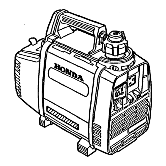
Page 8: 2: Component Identification
2. COMPONENT lDENTlFlCATlON DC 0icw RREAXER AC RECEPTACLE /. DC RECEPTACLE OUTPUT WDICATOR ‘AC OVERLOAO INDICATOR TERMWAL COVER... - Page 9 FUEL TANK CAP OtJTFUT FRAMi BEmAt. NUMBER...
-
Page 10: Pre-Operation Checks
3. PRE-OPERATION CHECKS CAUTION: Check the fpmerator on Mopped. FUEL The Honda EX36D has a mixture. Remove the filler cap and check the fuel level. Refill the tank with pre- mixed fuel if the fuel level ir low. Do not Your engine i de ‘gned to use any gasoline that has a pump oc- tane number ( v number of 91 or higher. -
Page 11: Starting The Engine
Fuel tank capacity: 0.81 I (0.21 US gal) Gasoline: Unleaded regular gasoline Oil: Honda 2-stroke oil or NMMA (BIA) certified service TC-W 2-stroke oil. Occasionally you may experience light spark knock while operating under heavy loads. This is no cause for concern, it simply means your engine is operating efficiently. - Page 12 AIR CLEANER The air cleaner accumulates dust and must be cleaned periodically. If the engine in operated in unusually dusty arean, the air cleaner must be cleaned at more frequent intervale than specified In the maintenance section. Check the air cleaner element to be sure it is clean and in good condition. Clean or replace the element if necessary (page 26).
- Page 13 1. Turn the fuel cap lever fully clockwise to the “ON” position. FUEL CAP LEVER 2. Disconnect any load from the AC receptacle and DC receptacle. The generator may be hard to start If a load Is connected. DC RECEPTACLE AC RECEPTAUB...
- Page 14 3. Move the engine switch to the CHOKE position. NOTE: If restarting a warmed-up engine, position. “Cold” Engine: 4. Pull the starter grip lightly until resistance is felt, then pull briskly. CAUTION: Do not allow generator. Return it gently to prevent damage to the housing. set the wtart “Hot”...
- Page 15 5. Turn the engine switch to the ON position as the engine warms up. NOTE: If the air temperature Is high, return the engine switch to ON as soon as the engine starts. The AC output indicator will light when the engine starts and will remain lit while the engine is running.
-
Page 16: Generator Use
5. GENERA-tOR USE Before connecting an appliance to it is in good working order, and that its electrfcal rating does not exceed that of the generator. NOTE: Appliance and power tool manufacturers usually list rating informa- tion near the model number or serial number. To ground the generator chassis, connect the ground terminal and an independent ground source. - Page 17 Connections for standby power: the generator will he used to supply power to a building’s electrical system as an alternative switch must be Installed before connecting the generator. The transfer switch disconnects the utility lines from the building’s electrical system when the generator is connected.
- Page 18 AC applkatlons 1. Start the engine and 2. Plug in the appliance. OVLRLiJAD MMCATOR mEENI CAUTION: For continuous operation, limit operation requiring the marlmum less. Substantial overbading dicator may damage the generator. Marginal overloading ly tights the overload generator. Be sure that ail appliances them to the generator.
-
Page 19: Output And Overload Indicators
OUTPUT AND OVERLOAD INDICATORS If the generator is overloaded fin excess of 350 VA), or If there is a short circuit in a connected appliance, the red overload light will go ON. The red overload light will stay ON, and after about ten seconds current to the connected appliancels) will shut off and the green light will go OFF. -
Page 20: Ac Applications
OUTPUT SELECTOR SWITCH Turn the output selector switch to either position as required. You can turn the switch to the 150 VA position for quiet generator operation, if 150 VA is sufficient to operate your AC appliance. Turn the switch to the 300 VA position for full generator output. NOTE: When using the DC output, always set the switch in the 300 VA position. -
Page 21: Dc Application
DC application The DC terminals may be used for charging 12 volt automotive-type bat- teries only. NOTE: When using the DC output, turn the output selector switch to the 300 VA position. 1. Start the generator. 2. Connect the red lead of the battery charging cable to the positive (+I battery terminal and the black lead to the negative f-1 battery terminal. - Page 22 Never lean over the battery when making connections. Never attempt to charge a frozen battery. The battery explode. If you suspect that a battery may be frozen, remove the vent caps and check the fluid. If there seems to be no fluid, or lf do not attempt to charge the battery untif the fluid thaws, CAUTION: s Be careful to connect...
-
Page 23: High Altitude Operation
High altitude operation At high altitude, the standard carburetor air-fuel mixture will be excessively rich. Performance will decrease, and fuel consumption will increase. High altitude performance can be improved by Installing a smaller diameter main fuel jet in the carburetor and readjusting the pilot screw. If you always operate the generator at altitudes higher than 6,000 feet above sea level, have your authorized Honda Generator dealer perform these carburetor modifications,... -
Page 24: Stopping The Engine
6. STOPPING THE ENGINE NOTE: To stop the engine In an emergency, turn the engine switch to the OFF position. In normal ~80: 1. Disconnect any load at the AC receptackt. Disconnect DC battery charging cable. 2. Turn the engine ewttch to the OFF positIon. - Page 25 3. Turn the fuel cap lever fully countqrclockwise to the “OFF” position. CAUTION: Be sure the fuel cap lever end the engina rwitch are “OFF” when stopping, transporting and/or storing the generator.
-
Page 26: Maintenance
7. MAINTENANCE Maintenance Schedule Periodic maintenance and adjustment is necessary to keep the generator in good operating condition. Perform the service and inspection scheduled in the table. Shut engine off the before pedormlng be run, make sure the area is well ventilated. carbon monoxide gas;... - Page 27 Maintenance Schedule ccrnburtion chamber Fud ten& and filter d.. ~~. NOTE: (11: Service more ~reqwntly when used ht rlurt~ MI. 121: These itemr houkl be aarvked by n authorbad Homb de&r. proper toob and IO rnechankrlly (31: Fofxod~nkrmt cornmarcW uao. lots tnurrr of oporrtbn First month 2otrs.
-
Page 28: Air Cleaner Service
Air Cleaner Service The air cleaner accumulates dust and must be cleaned periodically. If the engine is operated in unusually dusty areas, the air cleaner must be cleaned at more frequent intervals than specified in the maintenance section. A dirty air cleaner will restrict air flow to the carburetor. To prevent car- buretor malfunction, service the air cleaner regularly (page 24). -
Page 29: Spark Plug Service
Spark Plug Service Recommended spark plug: ensure engine operation, the spark plug must be properly gapped proper and free of deposits. If the engine has been running, the muffler careful not to touch the muffler. Remove the spark plug maintenance cover, then remove the spark plug cap. - Page 30 6. Make sure that the spark plug washer Is in good condition, and thread the spark plug in by hand to prevent cross-threading. After the spark plug is seeted, press the washer. NOTE: If installing a new spark plug, tighten 112 turn after the spark plug seats to compress the washer.
- Page 31 Amater Maintenanw Sparfc If the generator has been nmnlng, the muffler will be very hot. Allow it to cool before proceeding. CAUTION: The spa& arrester murt be servked every 100 hours to maln- tain its efficiency. 1. Remove the spark plug inspection 2.
-
Page 32: Exhaust Pipe Screen Maintenance
6. Use a brush to remove carbon deposits from the spark arrester screen. Inspect the screen for breaks or tears, and replace it if necessary. 7. Check the exhaust pipe gaskets; replace If damaged. Reinstall the muffler, muffler protector disassembly. Exhaust Pipe Screen Mafntenence Carefully clean the screen with a fine wire brush or a toothbrush. -
Page 33: Transporting/Storage
To prevent fuel spillage when transporting or during temporary storage, the generator should be secured upright in its normal operating position, with the engine switch OFF and the fuel cap lever turned fully counterclockwise to the “OFF” position. Spilled fuel or Before storing the unit 1. -
Page 34: Troubleshooting
9. TROUBLESHOOTING Engine will not start: Is the fuel cap lever fully ON7 Is the engine switch in the ON position? Is there enough fuel? Are all loads disconnected from the AC receptacle and DC receptacle? Is there a spark at the spark plug? 8. -
Page 35: Wiring Diagram
10. WIRING DIAGRAM... -
Page 36: Specifications
6.7 : 1 3,000/4,600 Forced air cooling C.D.I. 0.91 I (0.21 US gal) BMR-GA (NGK) W20MW-U (NIPPONDENSO) 12ov 60Ht 1.2512.5 150/309 VA 1501350 VA Only for charging 12 V automotive batteries. Maximum charging output = 6A EX350 Ii kg (19.7 lb) - Page 37 Honda Power Equipment dealership personnel are trained professionals. They should be able to answer any question you may have. If you encounter a problem that your dealer does not solve to your satisfaction, please discuss it with the dealership’s management. The Service Manager or General Man- ager can help.
- Page 38 MEMO...