Table of Contents
Advertisement
TopPage
In the interests of user-safety the oven should be restored to its original condition and only parts identical to those
specified should be used.
CHAPTER 1. BEFORE SERVICING
CHAPTER 2. WARNING TO SERVICE PERSONNEL
CHAPTER 3. PRODUCT SPECIFICATIONS
CHAPTER 4. APPEARANCE VIEW
CHAPTER 5. OPERATION SEQUENCE
CHAPTER 6. FUNCTION OF IMPORTANT COMPO-
NENTS
CHAPTER 7. TROUBLESHOOTING GUIDE
CHAPTER 8. TEST PROCEDURES
SERVICE MANUAL
MODEL
CONTENTS
CHAPTER 9. TOUCH CONTROL PANEL ASSEMBLY
CHAPTER 10. PRECAUTIONS FOR USING LEAD-
FREE SOLDER
CHAPTER 11. COMPONENT REPLACEMENT AND
ADJUSTMENT PROCEDURE
CHAPTER 12. MICROWAVE MEASUREMENT
CHAPTER 13. CIRCUIT DIAGRAMS
Parts List
S2901R395NPJS
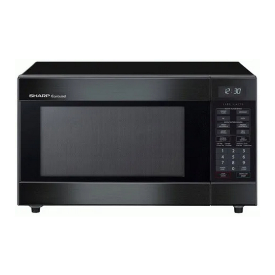
MICROWAVE OVEN
R-395N(S)
This document has been published to be used for
after sales service only.
The contents are subject to change without notice.
R395N(S)
Advertisement
Table of Contents

Related Manuals for Sharp R-395N


Summary of Contents for Sharp R-395N
-
Page 1: Microwave Oven
TopPage R395N(S) SERVICE MANUAL S2901R395NPJS MICROWAVE OVEN R-395N(S) MODEL In the interests of user-safety the oven should be restored to its original condition and only parts identical to those specified should be used. CONTENTS CHAPTER 1. BEFORE SERVICING CHAPTER 9. TOUCH CONTROL PANEL ASSEMBLY CHAPTER 2. -
Page 2: Table Of Contents
CONTENTS CHAPTER 1. BEFORE SERVICING [14] N: PROCEDURES TO BE TAKEN GENERAL IMPORTANT INFORMA- WHEN THE FOIL PATTERN ON THE TION ............1-1 PRINTED WIRING BOARD (PWB) IS CAUTION MICROWAVE RADIATION ..1-1 OPEN............8-5 WARNING.......... -
Page 3: Chapter 1. Before Servicing
[1] GENERAL IMPORTANT INFORMATION This Manual has been prepared to provide Sharp Corp. Service engineers with Operation and Service Information. It is recommended that service engineers carefully study the entire text of this manual, so they will be qualified to render satisfactory customer ser- vice. -
Page 4: Chapter 2. Warning To Service Person- Bly
If the water remains cold carry out 3D checks and Sharp recommend that wherever possible fault-finding is carried out reexamine the connections to the component being tested. with the supply disconnected. It may, in some cases, be necessary to... -
Page 5: Chapter 3. Product Specifications
R395N(S) CHAPTER 3. R395N(S) PRODUCT SPECIFICATIONS ITEM DESCRIPTION 230 - 240 Volts Power Requirements 50 Hertz Single phase, 3 wire earthed Power Consumption 1.6 k W 1100 watts nominal of RF microwave energy (IEC Test Procedure) Power Output Operating frequency 2450 MHz Width 520 mm Case Dimensions Height 310 mmincluding foot... -
Page 6: Chapter 4. Appearance View Oven
R395N(S) CHAPTER 4. R395N(S) APPEARANCE VIEW [1] OVEN 1. Door open button 2. Oven lamp 3. Door hinges 4. Door safety latches 5. See through door 6. Door seal and sealing surfaces 7. Coupling 8. Wave guide cover 9. Touch control panel 10.Liquid crystal display 11.Ventilation openings 12. -
Page 7: Chapter 5. Operation Sequence 1] Off Condition
R395N(S) CHAPTER 5. R395N(S) OPERATION SEQUENCE [1] OFF CONDITION 1) When the oven door is opened during or after the cycle of a cooking program, the 1st. latch switch and 2nd. interlock relay Closing the door activates all door interlock switches (1st. latch switch control switch must open their contacts first. -
Page 8: Chapter 6. Function Of Important Com
R395N(S) CHAPTER 6. R395N(S) FUNCTION OF IMPORTANT COMPONENTS [1] DOOR OPEN MECHANISM [6] OVEN TEMPERATURE FUSE The door is opened by pushing the open button on the control panel, The temperature fuse, located on the top of the oven cavity, is refer to the Figure D-1.When the open button is pushed, the open but- designed to prevent damage to the oven by fire.If the food load is over- ton pushes up the switch lever, and then the switch lever pushes up... -
Page 9: Chapter 7. Troubleshooting Guide Foreword
R395N(S) CHAPTER 7. R395N(S) TROUBLESHOOTING GUIDE [1] FOREWORD When troubleshooting the microwave oven, it is helpful to follow the IMPORTANT: Sequence of Operation in performing the checks. Many of the possible If the oven becomes inoperative because of a blown fuse F10A in the causes of trouble will require that a specific test be performed. -
Page 10: Chapter 8. Test Procedures
R395N(S) CHAPTER 8. R395N(S) TEST PROCEDURES [1] A: MAGNETRON (MG) TEST NEVER TOUCH ANY PART IN THE CIRCUIT WITH YOUR HAND OR AN INSULATED TOOL WHILE THE OVEN IS IN OPERATION. CARRY OUT 3D CHECKS. Isolate the magnetron from the high voltage circuit by removing all leads connected to the filament terminal. To test for an open circuit filament use an ohmmeter to make a continuity test between the magnetron filament terminals, the meter should show a reading of less than 1 ohm. -
Page 11: B: Power Transformer Test
R395N(S) 1000g 1000g 1000g T1 C T2 C Heat up for 41 sec. [2] B: POWER TRANSFORMER TEST WARNING: High voltages and large currents are present at the secondary winding and filament winding of the power transformer. It is very dangerous to work near this part when the oven is on. NEVER make any voltage measurements of the high-voltage cir- cuits, including the magnetron filament. -
Page 12: E: Switch Test
R395N(S) [5] E: SWITCH TEST CARRY OUT 3D CHECKS. Isolate the switch to be tested and using an ohmmeter check between the terminals as described in the following table. Table: Terminal Connection of Switch Plunger Operation Common terminal to Normally open terminal Common terminal to Normally close terminal Released Open circuit... -
Page 13: I: Noise Filter Test
R395N(S) [9] I: NOISE FILTER TEST CARRY OUT 3D CHECKS. Disconnect the leads from the terminals of the noise filter. Using an ohmmeter, check between the terminals as described in the following table. NOISE SUPPRESSION COIL MEASURING POINT INDICATION OF OHMMETER Between N and L Open circuit Between terminal N and WHITE... -
Page 14: L: Key Unit (Membrane Switch) Test
R395N(S) [12] L: KEY UNIT (MEMBRANE SWITCH) TEST If the display fails to clear when the STOP/CLEAR pad is (G13) depressed, first verify the flat ribbon cable is making good contact, verify that the 2nd. interlock relay control switch operates properly; that is the contacts are closed when the door is closed and open when the door is open. -
Page 15: Chapter 9. Touch Control Panel Assem
R395N(S) CHAPTER 9. R395N(S) TOUCH CONTROL PANEL ASSEMBLY [1] OUTLINE OF TOUCH CONTROL PANEL The touch control section consists of the following units. (1) Key Unit (2) Control Unit (The Control Unit consists of Power Unit and LSI Unit). The principal functions of these units and the signals communicated among them are explained below. 1. - Page 16 R395N(S) 1) Disconnect the power supply cord, and then remove outer case. 2) Open the door and block it open. 3) Discharge high voltage capacitor. 4) Disconnect the leads to the primary of the power transformer. 5) Ensure that these leads remain isolated from other components and oven chassis by using insulation tape. 6) After that procedure, re-connect the power supply cord.
-
Page 17: Chapter 10. Precautions For Using Lead-Free Solder
R395N(S) CHAPTER 10. R395N(S) PRECAUTIONS FOR USING LEAD-FREE SOLDER 1. Employing lead-free solder The “Main PWB” of this model employs lead-free solder. This is indicated by the “LF” symbol printed on the PWB and in the service manual. The suffix letter indicates the alloy type of the solder. -
Page 18: And Adjustment Procedure 1] Before Operating
Please refer to ”OVEN PARTS, CABINET PARTS, DOOR PARTS”, when carrying out any of the following removal procedures: WARNING FOR WIRING To prevent an electric shock, take the following precautions. 3) Sharp edge: 1. Before wiring, Bottom plate, Oven cavity, Weveguide flange, Chassis support and other metallic plate. -
Page 19: Power Transformer Removal
R395N(S) [3] POWER TRANSFORMER REMOVAL 1. REMOVAL 2. RE-INSTALL 1. CARRY OUT 3D CHECKS. 1. Rest transformer on the bottom plate with its primary terminals toward the oven face plate. 2. Disconnect wire leads (primary) from the power transformer. 2. Secure transformer with four (4) screws (two (2) screws from the 3. -
Page 20: Control Panel Assembly Removal
4. Where the corners have been snipped off bend corner areas flat. 8. After replacement use the one (1) screw (XHPS740P08K00) to fit No sharp edges must be evident after removal of the turntable the turntable motor cover. motor cover. -
Page 21: Power Supply Cord Replacement
R395N(S) 4. Install the fan blade to the shaft of fan motor by pushing the fan • Make sure that the fan blade rotates smooth afterinstal- blade with a small, light weight, ball peen hammer or rubber mallet. lation. 5. Install the fan motor assembly to the oven cavity back plate with •... -
Page 22: 1St. Latch Switch, 2Nd. Interlock Relay Control Switch And Monitor Switch Adjustment
R395N(S) [13] 1ST. LATCH SWITCH, 2ND. INTERLOCK RELAY CONTROL SWITCH AND MONITOR SWITCH ADJUSTMENT 1. Adjustment 2. The 1st. latch switch and 2nd. interlock relay controls witch inter- rupt the circuit before the door can be opened. If the 1st. latch switch, 2nd. interlock relay control switch and monitor 3. - Page 23 R395N(S) 2) An approved microwave survey meter should be used to assure 4. SEALER FILM compliance with proper microwave radiation emission limitation 1. Put the adhesive tape on the backing film of the sealer film as standards. shown in Fig. C-7 3.
-
Page 24: Chapter 12. Microwave Measurement
R395N(S) CHAPTER 12. R395N(S) MICROWAVE MEASUREMENT After adjustment of door latch switches, monitor switch and door are completed individually or collectively, the following leakage test must be per- formed with a survey instrument and it must be confirmed that the result meets the requirements of the performance standard for microwave oven. REQUIREMENT The safety switch must prevent microwave radiation emission in excess of 5mW/cm at any point 5cm or more from external surface of the oven. -
Page 25: Chapter 13. Circuit Diagrams
R395N(S) CHAPTER 13. R395N(S) CIRCUIT DIAGRAMS [1] Oven Schematic SCHEMATIC NOTE: CONDITION OF OVEN 1. DOOR CLOSED. 2. CLOCK APPEARS ON DISPLAY. TEMPERATURE NOISE FILTER FUSE 150ûC (OVEN) FUSE F10A RY-2 2ND. INTERLOCK CONTROL RELAY UNIT CAPACITOR 1.07μ AC2300V 2ND. INTERLOCK RELAY CONTROL SWITCH RY-1... -
Page 26: Pictorial Diagram (Figure S-1)
R395N(S) [2] Pictorial Diagram (Figure S-1) LIVE Figure S-1. Pictorial Diagram 13 – 2... -
Page 27: Control Unit Circuit (Figure S-2)
R395N(S) [3] Control Unit Circuit (Figure S-2) COM3 COM2 COM1 COM0 SEG4 SEG16 SEG5 SEG15 SEG6 SEG14 SEG7 SEG13 SEG8 SEG12 4.7K SEG9 SEG11 OSCSEL SEG10 SEG10 R110 RESET SEG11 SEG9 SEG12 SEG8 SEG13 SEG7 SEG14 SEG6 SEG15 SEG5 XOUT SEG16 SEG4 SEG17... -
Page 28: Printed Wiring Board (Figure S-3)
R395N(S) [4] Printed Wiring Board (Figure S-3) Figure S-3. Printed Wiring Board of Power Unit 13 – 4...