Table of Contents
Advertisement
Advertisement
Table of Contents

Summary of Contents for Datavideo PTC-100
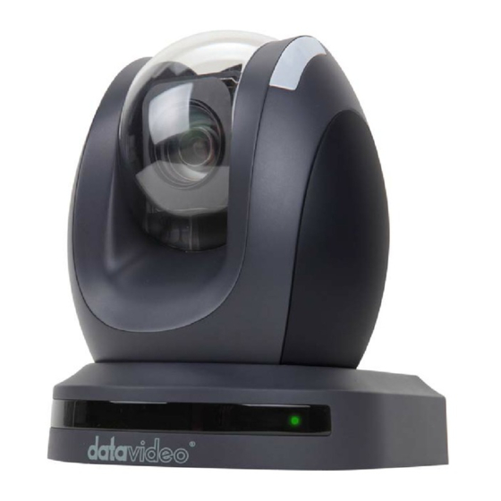
- Page 1 Full HD PTZ Camera PTC-100 INSTRUCTION MANUAL www.datavideo-tek.com...
-
Page 2: Table Of Contents
Introduction ................................5 Product Overview ..............................5 Features .................................. 5 Connections & Controls ............................6 PTC-100 Front View ............................6 PTC-100 Rear View ............................7 PTC-100 Bottom View ............................9 PTC-100 Installation Guide ..........................12 OSD Operational Description ..........................16 CAMERA SETUP >... -
Page 3: Warnings And Precautions
This product should only be operated from the type of power source indicated on the marking label of the AC adapter. If you are not sure of the type of power available, consult your Datavideo dealer or your local power company. -
Page 4: Warranty
Certain parts with limited lifetime expectancy such as LCD Panels, DVD Drives, Hard Drives are only covered for the first 10,000 hours, or 1 year (whichever comes first). Any second year warranty claims must be made to your local Datavideo office or one of its authorized Distributors before the extended warranty expires. Disposal For EU Customers only - WEEE Marking This symbol on the product indicates that it should not be treated as household waste. -
Page 5: Introduction
In addition, you’ll find some useful background information on video and audio. Product Overview The PTC-100 not only meets your request for true full 1920 x 1080 HD qualities, but also provides an array of simple-to-operate features. Features ... -
Page 6: Connections & Controls
Connections & Controls PTC-100 Front View Item Illustration Name Description Lens Built-in 1/3” Sony Exmor 3.0MP CMOS HD color camera with white balance control, backlight compensation settings, automatic gain settings etc. Shown above Tally LED Tally lamp lights-up when tally signal has been transmitted to the tally signal box. -
Page 7: Ptc-100 Rear View
PTC-100 Rear View Item Illustration Function Description SW2: Bold letters indicates factory default value. IRID&DVIP Setup Setup Switch Number IRID #1 #2 Off Off CAM 1 On Off CAM 2 Off On CAM 3 On On CAM 4 Setup Switch Number... - Page 8 Item Illustration Function Description HD-SDI OUT Video signal output 800mV+-10% 75Ω BNC CVBS OUT Video signal output CVBS 1. 0Vp-p 75Ω BNC HDMI OUT Video signal output16-bit YCbCr 4:2:2 Power Input DC 12V Input, maximum power consumption is 2A Terminal DVIP Set #3 of SW2 to OFF to connect RJ45 and DVIP.
-
Page 9: Ptc-100 Bottom View
PTC-100 Bottom View Item Illustration Function Description PTZ screw hole Shown above SW1: DIP Switch PTZ cameras can be connected in series of up to setup 225 devices; each PTZ camera has its own ID number and may not be repeated. - Page 10 SW1: ID Setup: PTZ cameras can be connected in series of up to 225 devices; each PTZ camera has its own ID number and may not be repeated.
- Page 11 DIP switch setting, as shown below: Set to 000, then the image display will show: ID 1.
-
Page 12: Ptc-100 Installation Guide
PTC-100 Installation Guide Step 1 Set the IMAGE FLIP switch on the rear panel to ON. Step 2 Attach the retaining wire to the junction box in the ceiling. Use a screw hole and a screw (not supplied) in the junction box to attach the retaining wire. - Page 13 Step 4 Attach the ceiling bracket (A) to the bottom of the camera using the 3 screws. Align the screw holes on the bottom of the camera with those in the ceiling bracket to the camera. Tighten the screws a bit at a time in the numbered order shown in the illustration. Attach the retaining wire ○...
- Page 14 Step 5 Insert the protrusions raised on the ceiling bracket (A) into the spaces prepared in the ceiling bracket (B), and temporarily attach them by pushing the ceiling bracket (A) to the rear. Step 6 While pushing up on the front part of the camera, attach it using the three screws provided, starting with the screw at position.
-
Page 15: Removing The Camera
Step 7 Connect the cables to the connectors on the rear of the camera. Removing the camera Step 1 Remove the 3 screws used to attach the camera in step 6 of “Installation”. Step 2 While pushing the entire camera up towards the ceiling, move the camera to the front. The hooks will disengage, and you can remove the camera. -
Page 16: Osd Operational Description
OSD Operational Description ◎ Selection marked as "*", represents factory default value Menu Tree Structure MAIN MODE ITEM NOTES MENU FOCUS DZOOM ON/ OFF* DEFAULT Return to default setup AUTO* RETURN Return to previous setup page DZOOM ON/ OFF* MANUAL DEFAULT Return to default setup RETURN... - Page 17 DAY/ NIGHT DEFAULT Return to default setup RETURN Return to previous setup page DEFAULT Return to default setup DAY* RETURN Return to previous setup page DEFAULT Return to default setup NIGHT RETURN Return to previous setup page WHITE BALANCE DEFAULT Return to default setup AUTO* RETURN...
- Page 18 HORIZONTAL 0> 1> ...> 96*> 97> ...> 198> 199 VERTICAL 0> 1> ...> 36* > 37> ...> 98> 99 1080/ 50i (PAL) DEFAULT Return to default setup RETURN Return to previous setup page HORIZONTAL 0> 1> ...> 96*> 97> ...> 198> 199 VERTICAL 0>...
-
Page 19: Camera Setup > Focus Setup
CAMERA SETUP > FOCUS SETUP Users can setup focus application. Factory settings as shown below: FOCUS MODE Auto DZOOM TRIGGER DEFAULT RETURN MODE: This function is used for setting up focus mode, it can be set to Auto/ Manual/ Push Auto. 1. -
Page 20: Camera > Day/ Night
GAIN LIMIT: Setup Gain Limit, setup range = 0~28 (Default Setup: 6). SHUTTER: Shutter Speed consist of 5 types of mode: NTSC: 1/1,1/2,1/30,1/60,1/10000 and PAL: 1/1,1/2, 1/25,1/60,1/10000 (Default Setup: 1/30). IRIS: Setup Iris value, iris setup range = F14~F1.6 (Default Setup: F1.6). ... -
Page 21: Camera > White Balance
CAMERA > WHITE BALANCE Users can setup white balance application. Factory settings as shown below: WHITE BALANCE MODE AUTO AUTO MANUAL PUSH AUTO DEFUALT RETURN MODE: Three types of WB mode setup: AUTO/ MANUAL/ PUSH AUTO (Default Setup: AUTO). ... -
Page 22: Camera Setup > Effect Setup
CAMERA SETUP > EFFECT SETUP User can setup some image application and effect. Factory settings are as shown below: EFFECT SETUP NEGATIVE MIRROR FREEZE DEFAULT RETURN NEGATIVE: Negative effect can be set to ON/ OFF (Default Setup: OFF). MIRROR: Three Types of MIRROR mode: OFF/ HORIZONTAL/ ROTATE (Default Setup: OFF). -
Page 23: Video Setp
SPEED (DPS): Setup the moving speed, higher the value faster the speed. DWELL TIME (SEC): Setup the dwell time after cruise function stops (Dwell Time Range: 1~127 Sec.). EXECUTE: Precede preset function. DEFAULT: Return to default setup. ... -
Page 24: Osd Setup
OSD SETUP OSD SETUP ID DISPLAY TITLE DISPLAY TITLE EDIT TITLE ZOOM RATIO LANGUAGE ENGLISH DEFAULT RETURN ID DISPLAY: To reveal or hide ID, can be set to ON/ OFF. TITLE DISPLAY: To reveal or hide Title, can be set to ON/ OFF. ... -
Page 27: Remote Controller Button Description
Remote Controller Button Description Menu Setup PTC-100 requires HDMI monitor to browse the current setup status, and operation setup using keyboard or remote controller buttons: MENU/ UP/ DOWN/ LEFT/ RIGHT/ A/FOCUS. Setup methods of all menu function items are similar. Press the MENU button to enter or exit camera menu options, press UP or DOWN arrow button to select the menu option. - Page 28 Item Illustration Function Description Color Bar Setup Use the MODE button to setup and adjust (MODE) the screen brightness and color density. Press RESET button to face the camera PAN/ TILT Control (RESET) back to the front. Camera Select Operating more than one camera with (CAM1~CAM4) the Remote Controller.
- Page 29 Item Illustration Function Description Auto Focus Control To focus the camera on a subject (A/ FOCUS) automatically Press the A/ FOCUS button. The camera focuses on the subject at the center of the screen automatically. Exit Sub-Menu Option Press A/ FOCUS button to exit sub-menu option.
- Page 30 Item Illustration Function Description Enter/ Exit Camera Enter or Exit Camera Menu Option Menu Option Zoom in/ Zoom Out Zooming Press either TELE button to zoom-in when Button Enlarge Image (TELE) the subject appears close to the camera or Minimize Image (WIDE) WIDE button to zoom-out when the subject appears far away from the camera.
-
Page 31: Specification
Specification PTC-100 SD/ HD Item No. HD-SDI/HDMI + CVBS PTZ Camera Description Video Image Device 1/3” Sony Exmor 3.0MP CMOS sensor Picture Elements Approx. 3M (1920H × 1080V) Resolution SD / HD / FHD Signal system 480i (CBS) 576i (CBS) 720_50p/720_59.94p/... - Page 32 Motion Detection MD Sensitivity Alarm Privacy Masking White Balance Auto(ATW) / Manual / Push Auto Auto/Manual Gain Control (6 to 28 dB, 2 dB steps) Back Light Comp. On / Off Digital Zoom Mirror Horizontal / Rotate Freeze On / Off Positive / Negative On / Off Color Bar...
- Page 33 Day / Night IR-Cut filter Removable IR Distance LED (pcs/angle) Light Transistor Wavelength Lens Lens Type Mototized 20X Zoom Focal Length f=4.7 mm (W) to 94.0 mm (T) Aperture Range F1.6 to F3.5 Angle of View 54.1°(W-end) to 2.9°(T-end) Aspect ratio 16 : 9 Lens Control DC / Manual...
- Page 34 Protocol Pelco D/ P; Sony VISCA Baud Rate 9600bps Video Output (HD) HD-SDI (BNC)/ HDMI Video Output (SD) Video Format Output 1Vp-p/ 75Ohms. Audio Heater Tally LED 2 LED Built in the PTZ Zoom Module Side Dimension (incl. BNC) 218mm (H) x 173mm (W) x 185.5mm (D) Weight 2.25 Kg DC12±10%...
-
Page 35: Service & Support
It is our goal to make your products ownership a satisfying experience. Our supporting staff is available to assist you in setting up and operating your system. Please refer to our web site www.datavideo-tek.com for answers to common questions, support requests or contact your local office below.